Page 3775 of 5267
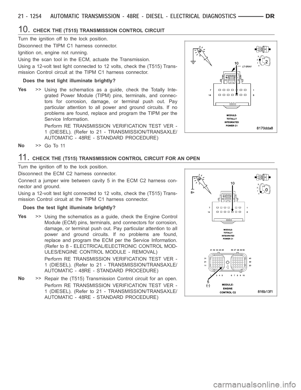
10.CHECK THE (T515) TRANSMISSION CONTROL CIRCUIT
Turn the ignition off to the lock position.
Disconnect the TIPM C1 harness connector.
Ignition on, engine not running.
Using the scan tool in the ECM, actuate the Transmission.
Using a 12-volt test light connected to 12 volts, check the (T515) Trans-
mission Control circuit at the TIPM C1 harness connector.
Does the test light illuminate brightly?
Ye s>>
Using the schematics as a guide, check the Totally Inte-
grated Power Module (TIPM) pins, terminals, and connec-
tors for corrosion, damage, or terminal push out. Pay
particular attention to all power and ground circuits. If no
problems are found, replace and program the TIPM per the
Service Information.
Perform RE TRANSMISSION VERIFICATION TEST VER -
1 (DIESEL). (Refer to 21 - TRANSMISSION/TRANSAXLE/
AUTOMATIC - 48RE - STANDARD PROCEDURE)
No>>
Go To 11
11 .CHECK THE (T515) TRANSMISSION CONTROL CIRCUIT FOR AN OPEN
Turn the ignition off to the lock position.
Disconnect the ECM C2 harness connector.
Connect a jumper wire between cavity 5 in the ECM C2 harness con-
nector and ground.
Using a 12-volt test light connected to 12 volts, check the (T515) Trans-
mission Control circuit at the TIPM C1 harness connector.
Does the test light illuminate brightly?
Ye s>>
Using the schematics as a guide, check the Engine Control
Module (ECM) pins, terminals, and connectors for corrosion,
damage, or terminal push out. Pay particular attention to all
power and ground circuits. If no problems are found,
replace and program the ECM per the Service Information.
(Refer to 8 - ELECTRICAL/ELECTRONIC CONTROL MOD-
ULES/ENGINE CONTROL MODULE - REMOVAL)
Perform RE TRANSMISSION VERIFICATION TEST VER -
1 (DIESEL). (Refer to 21 - TRANSMISSION/TRANSAXLE/
AUTOMATIC - 48RE - STANDARD PROCEDURE)
No>>
Repair the (T515) Transmission Control circuit for an open.
Perform RE TRANSMISSION VERIFICATION TEST VER -
1 (DIESEL). (Refer to 21 - TRANSMISSION/TRANSAXLE/
AUTOMATIC - 48RE - STANDARD PROCEDURE)
Page 3779 of 5267
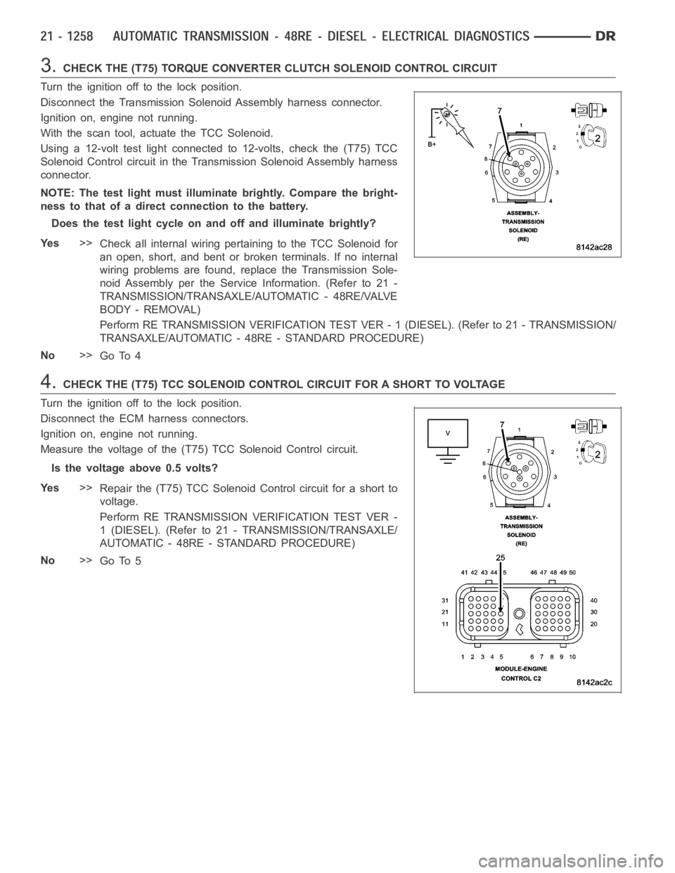
3.CHECK THE (T75) TORQUE CONVERTER CLUTCH SOLENOID CONTROL CIRCUIT
Turn the ignition off to the lock position.
Disconnect the Transmission Solenoid Assembly harness connector.
Ignition on, engine not running.
With the scan tool, actuate the TCC Solenoid.
Using a 12-volt test light connected to 12-volts, check the (T75) TCC
Solenoid Control circuit in the Transmission Solenoid Assembly harness
connector.
NOTE: The test light must illuminate brightly. Compare the bright-
ness to that of a direct connection to the battery.
Does the test light cycle on and off and illuminate brightly?
Ye s>>
Check all internal wiring pertaining to the TCC Solenoid for
an open, short, and bent or broken terminals. If no internal
wiring problems are found, replace the Transmission Sole-
noid Assembly per the Service Information. (Refer to 21 -
TRANSMISSION/TRANSAXLE/AUTOMATIC - 48RE/VALVE
BODY - REMOVAL)
Perform RE TRANSMISSION VERIFICATION TEST VER - 1 (DIESEL). (Refer to 21 - TRANSMISSION/
TRANSAXLE/AUTOMATIC - 48RE - STANDARD PROCEDURE)
No>>
Go To 4
4.CHECK THE (T75) TCC SOLENOID CONTROL CIRCUIT FOR A SHORT TO VOLTAGE
Turn the ignition off to the lock position.
Disconnect the ECM harness connectors.
Ignition on, engine not running.
Measure the voltage of the (T75) TCC Solenoid Control circuit.
Is the voltage above 0.5 volts?
Ye s>>
Repair the (T75) TCC Solenoid Control circuit for a short to
voltage.
Perform RE TRANSMISSION VERIFICATION TEST VER -
1 (DIESEL). (Refer to 21 - TRANSMISSION/TRANSAXLE/
AUTOMATIC - 48RE - STANDARD PROCEDURE)
No>>
Go To 5
Page 3780 of 5267
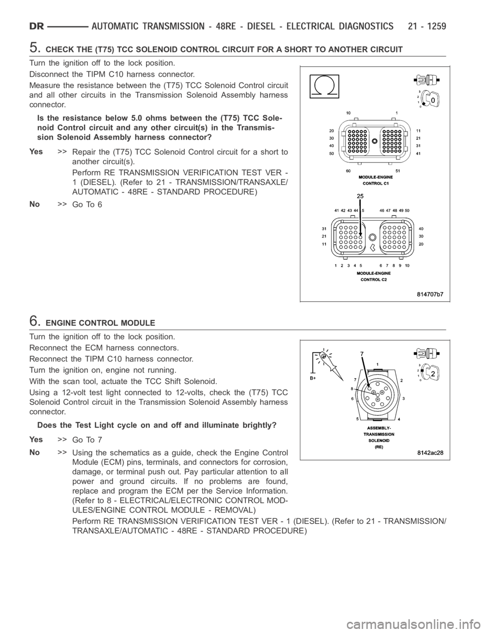
5.CHECK THE (T75) TCC SOLENOID CONTROL CIRCUIT FOR A SHORT TO ANOTHER CIRCUIT
Turn the ignition off to the lock position.
Disconnect the TIPM C10 harness connector.
Measure the resistance between the (T75) TCC Solenoid Control circuit
and all other circuits in the Transmission Solenoid Assembly harness
connector.
Is the resistance below 5.0 ohms between the (T75) TCC Sole-
noid Control circuit and any other circuit(s) in the Transmis-
sion Solenoid Assembly harness connector?
Ye s>>
Repair the (T75) TCC Solenoid Control circuit for a short to
another circuit(s).
Perform RE TRANSMISSION VERIFICATION TEST VER -
1 (DIESEL). (Refer to 21 - TRANSMISSION/TRANSAXLE/
AUTOMATIC - 48RE - STANDARD PROCEDURE)
No>>
Go To 6
6.ENGINE CONTROL MODULE
Turn the ignition off to the lock position.
Reconnect the ECM harness connectors.
Reconnect the TIPM C10 harness connector.
Turn the ignition on, engine not running.
With the scan tool, actuate the TCC Shift Solenoid.
Using a 12-volt test light connected to 12-volts, check the (T75) TCC
Solenoid Control circuit in the Transmission Solenoid Assembly harness
connector.
Does the Test Light cycle on and off and illuminate brightly?
Ye s>>
Go To 7
No>>
Using the schematics as a guide, check the Engine Control
Module (ECM) pins, terminals, and connectors for corrosion,
damage, or terminal push out. Pay particular attention to all
power and ground circuits. If no problems are found,
replace and program the ECM per the Service Information.
(Refer to 8 - ELECTRICAL/ELECTRONIC CONTROL MOD-
ULES/ENGINE CONTROL MODULE - REMOVAL)
Perform RE TRANSMISSION VERIFICATION TEST VER - 1 (DIESEL). (Refer to 21 - TRANSMISSION/
TRANSAXLE/AUTOMATIC - 48RE - STANDARD PROCEDURE)
Page 3783 of 5267
Theory of Operation
The tow/haul overdrive OFF (control) switch is located in the shift lever arm. The switch is a momentary contact
device that signals the ECM/PCM to toggle current status of the overdrive function. At ignition on, overdrive oper-
ation is allowed. Pressing the Tow/Haul Overdrive Off switch once causes the Tow/haul Overdrive OFF mode to be
entered and the Tow/Haul lamp to be illuminated. Pressing the switch a second time causes normal overdrive oper-
ationtoberestoredandtheTow/haullamptobeturnedoff.TheTow/haulOverdrive OFF mode defaults to ON after
the ignition switch is cycled OFF and ON. The normal position for the control switch is the ON position. The switch
must be in this position to energize the solenoid and allow a 3-4 upshift. The control switch indicator light illuminates
only when the Tow/haul Overdrive Off switch is turned to the OFF position, or when illuminated by the transmission
control module.
Possible Causes
TOW/HAUL OVERDRIVE OFF SWITCH SENSE CIRCUIT SHORT TO GROUND
TOW/HAUL OVERDRIVE OFF SWITCH
ENGINE CONTROL MODULE
Always perform the Pre-Diagnostic Troubleshooting procedure before proceeding. (Refer to 8 - ELECTRI-
CAL/ELECTRONIC CONTROL MODULES/TRANSMISSION CONTROL MODULE - DIAGNOSIS AND TESTING)
Diagnostic Test
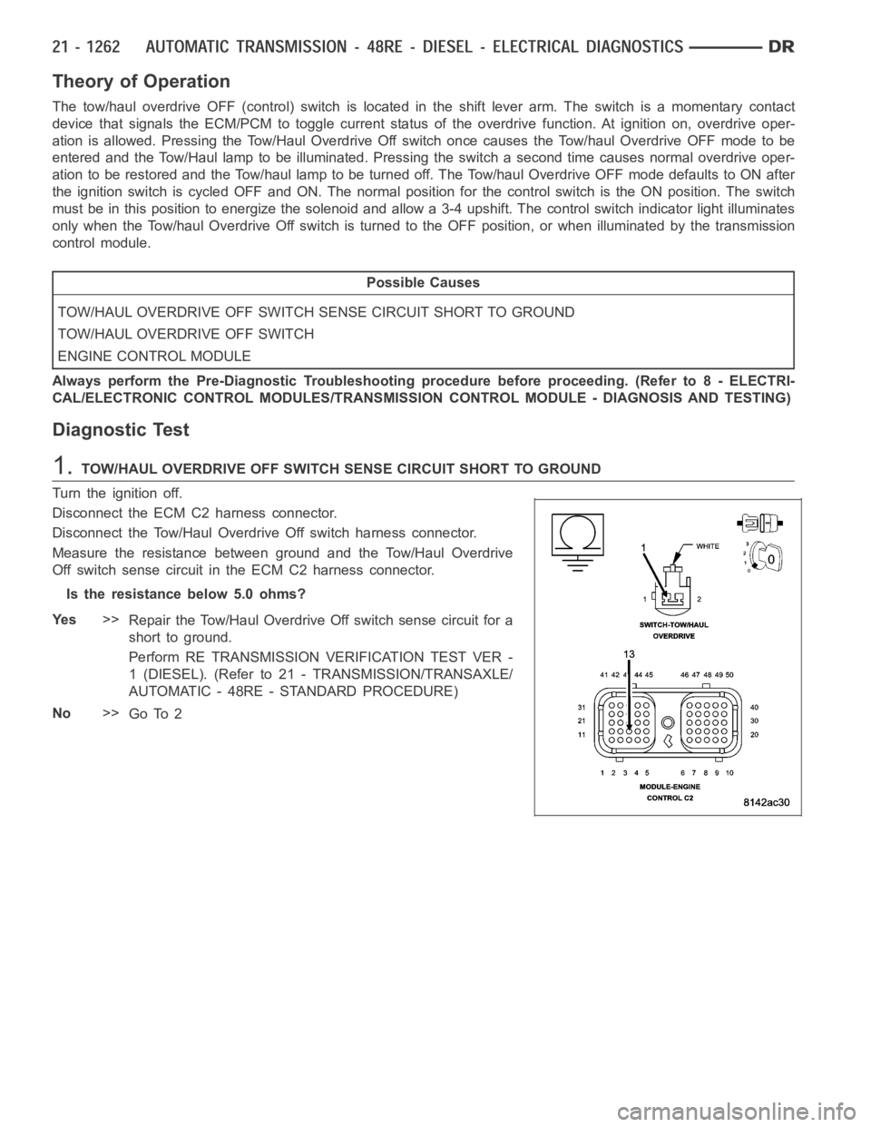
1.TOW/HAUL OVERDRIVE OFF SWITCH SENSE CIRCUIT SHORT TO GROUND
Turn the ignition off.
Disconnect the ECM C2 harness connector.
Disconnect the Tow/Haul OverdriveOff switch harness connector.
Measure the resistance between ground and the Tow/Haul Overdrive
Off switch sense circuit in the ECM C2 harness connector.
Is the resistance below 5.0 ohms?
Ye s>>
Repair the Tow/Haul Overdrive Off switch sense circuit for a
short to ground.
Perform RE TRANSMISSION VERIFICATION TEST VER -
1 (DIESEL). (Refer to 21 - TRANSMISSION/TRANSAXLE/
AUTOMATIC - 48RE - STANDARD PROCEDURE)
No>>
Go To 2
Page 3817 of 5267
19. On 4X4 models, disconnect shift rod from transfer
case shift lever.
20. Support rear of engine with safety stand or jack.
21. Raise transmission slightly with service jack to
relieve load on crossmember and supports.
22. Remove the nuts (3) securing rear support (1) to
the transmission crossmember.
23. Remove the bolts(2) holding the rear support (1)
to the transmission (5) remove the rear support.
24. Remove bolts attaching crossmember to frame
and remove crossmember.
25. On 4X4 models, remove transfer case. (Refer to
21 - TRANSMISSION AND TRANSFER CASE/
TRANSFER CASE - REMOVAL)
26. Remove fill tube (7) bracket bolts and pull tube
out of transmission. Retain fill tube seal (6). On
4X4 models, it will also be necessary to remove
bolt attaching transfer case vent tube to converter
housing.
27. Disconnect fluid cooler lines (6, 7) at transmission
(5), diesel engines.
Page 3823 of 5267
19. Loosen front band adjusting screw until band is
completely loose.
20. Remove front band strut (2) and anchor (3).
21. Squeeze front band (1) together slightly and slide
band over front clutch retainer (2) and out of
case.
Page 3828 of 5267
The use of crocus cloth is permissible where necessary, providing it is usedcarefully.Whenusedonshafts,or
valves, use extreme care to avoid rounding off sharp edges. Sharp edges arevital as they prevent foreign matter
from getting between the valve and valve bore.
Do not reuse oil seals, gaskets, seal rings, or O-rings during overhaul. Replace these parts as a matter of course.
Also do not reuse snap rings or E-clips that are bent or distorted. Replace these parts as well.
ASSEMBLY
Do not allow dirt, grease, or foreign material to enter the case or transmission components during assembly. Keep
the transmission case and components clean. Also make sure the tools and workbench area used for reassembly
operations are equally clean.
Shop towels used for wiping off tools and your hands must be made fromlint freematerials. Lint will stick to trans-
mission parts and could interfere with valve operation or even restrict fluid passages.
Lubricate transmission clutch and gear components with Mopar
ATF +4 during reassembly. Soak clutch discs in
transmission fluid before installation.
Use petroleum jelly on piston seals and o-rings to ease installation. Petroleumjellycanalsobeusedtolubricate
and hold thrust washers and plates in position during assembly.
Do not use chassis grease, bearing grease, white grease, or similar lubricants on any part.These types of
lubricants can eventually block or restrict fluid passages and valve operation. Use petroleum jelly only.
Do not force parts into place. The transmission components and sub-assemblies are easily installed by hand when
properly aligned. If a part seems difficult to install, it is either misaligned or incorrectly assembled. Verify that thrust
washers, thrust plates and seal rings are correctly positioned.
The planetary geartrain, front/rear clutch assemblies and oil pump are all much easier to install when the transmis-
sion case is upright. Either tilt the case upward with wood blocks, or cut a hole in the bench large enough for the
intermediate shaft and rear support. Then lower the shaft and support intothe hole and support the rear of the case
directly on the bench.
FRONT/REAR SERVO
1. Lubricate rear servo piston seal with ATF +4. Lubri-
cateservoboreincasewithATF+4.
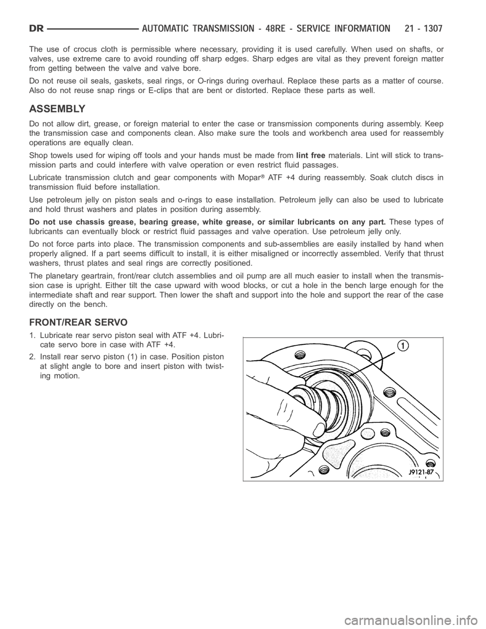
2. Install rear servo piston (1) in case. Position piston
at slight angle to bore and insert piston with twist-
ing motion.
Page 3829 of 5267
3. Install rear servo spring (1) and retainer (3) in case
bore. Be sure spring (1) is seated on piston (2).
4.CompressrearservopistonwithC-clamp(2)or
Valve Spring Compressor C-3422-B and install
servopistonsnap-ring(4).
5. Lubricate front servo piston (2) components and
servo bore in case with transmission fluid.
6. Install front servo piston (2) in bore. Carefully “run”
small, suitable tool (1) around piston ring to press it
back into groove and ease installation. Rotate pis-
tonintoboreatsametime.Rockpistonslightlyto
ease piston ring past snap-ring groove and into
bore.