2006 DODGE RAM SRT-10 light
[x] Cancel search: lightPage 3838 of 5267
INSTALLATION
1. Check torque converter hub inner and outer diam-
eters and hub drive notches for sharp edges burrs,
scratches, or nicks. Polish the hub and notches
with 320/400 grit paper and crocus cloth if neces-
sary. The hub must be smooth to avoid damaging
pump seal at installation.
2. Lubricate pocket in the rear oil pump seal lip with
transmission fluid.
3. Lubricate converter pilot hub of the crankshaft with
a light coating of Mopar
High Temp Grease.
4. Align and install converter in oil pump.
5. Carefully insert converter in oil pump. Then rotate
converter back and forth until fully seated in pump
gears.
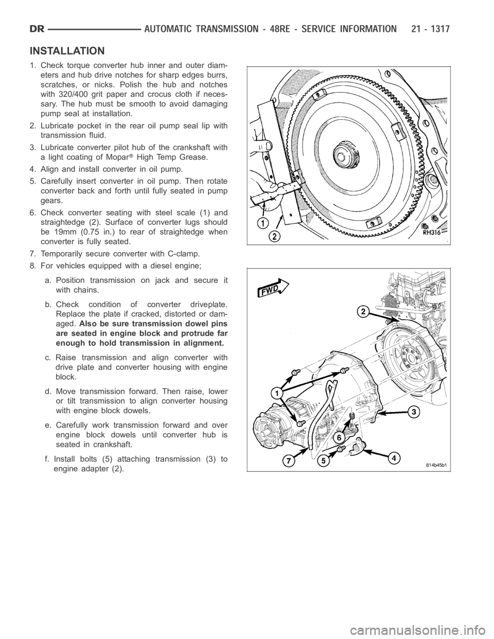
6. Check converter seating with steel scale (1) and
straightedge (2). Surface of converter lugs should
be 19mm (0.75 in.) to rear of straightedge when
converter is fully seated.
7. Temporarily secure converter with C-clamp.
8. For vehicles equipped with a diesel engine;
a. Position transmission on jack and secure it
with chains.
b. Check condition of converter driveplate.
Replace the plate if cracked, distorted or dam-
aged.Also be sure transmission dowel pins
are seated in engine block and protrude far
enough to hold transmission in alignment.
c. Raise transmission and align converter with
drive plate and converter housing with engine
block.
d. Move transmission forward. Then raise, lower
or tilt transmission to align converter housing
with engine block dowels.
e. Carefully work transmission forward and over
engine block dowels until converter hub is
seated in crankshaft.
f. Install bolts (5) attaching transmission (3) to
engine adapter (2).
Page 3864 of 5267
BANDS
DESCRIPTION
KICKDOWN (FRONT) BAND
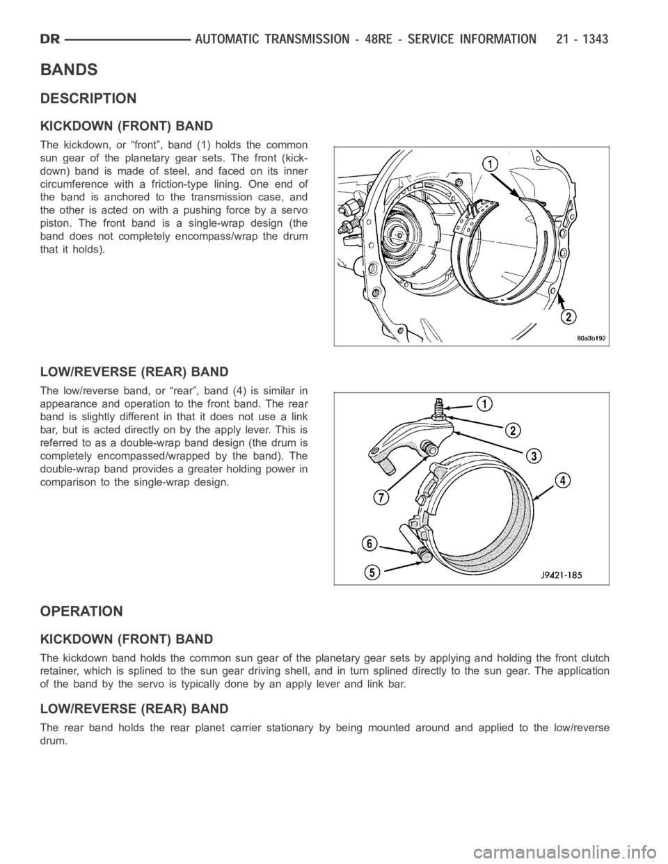
The kickdown, or “front”, band (1) holds the common
sun gear of the planetary gear sets. The front (kick-
down) band is made of steel, and faced on its inner
circumference with a friction-type lining. One end of
the band is anchored to the transmission case, and
the other is acted on with a pushing force by a servo
piston. The front band is a single-wrap design (the
band does not completely encompass/wrap the drum
that it holds).
LOW/REVERSE (REAR) BAND
The low/reverse band, or “rear”, band (4) is similar in
appearance and operation to the front band. The rear
band is slightly different in that it does not use a link
bar, but is acted directly on by the apply lever. This is
referred to as a double-wrap band design (the drum is
completely encompassed/wrapped by the band). The
double-wrap band provides a greater holding power in
comparison to the single-wrap design.
OPERATION
KICKDOWN (FRONT) BAND
The kickdown band holds the common sun gear of the planetary gear sets by applying and holding the front clutch
retainer, which is splined to the sungear driving shell, and in turn splineddirectlytothesungear.Theapplication
of the band by the servo is typically done by an apply lever and link bar.
LOW/REVERSE (REAR) BAND
The rear band holds the rear planet carrier stationary by being mounted around and applied to the low/reverse
drum.
Page 3915 of 5267
NOTE: The direct clutch in a 48RE transmission
uses 10 double-sided clutch discs.
17. Assemble and install direct clutch pack on hub as
follows:
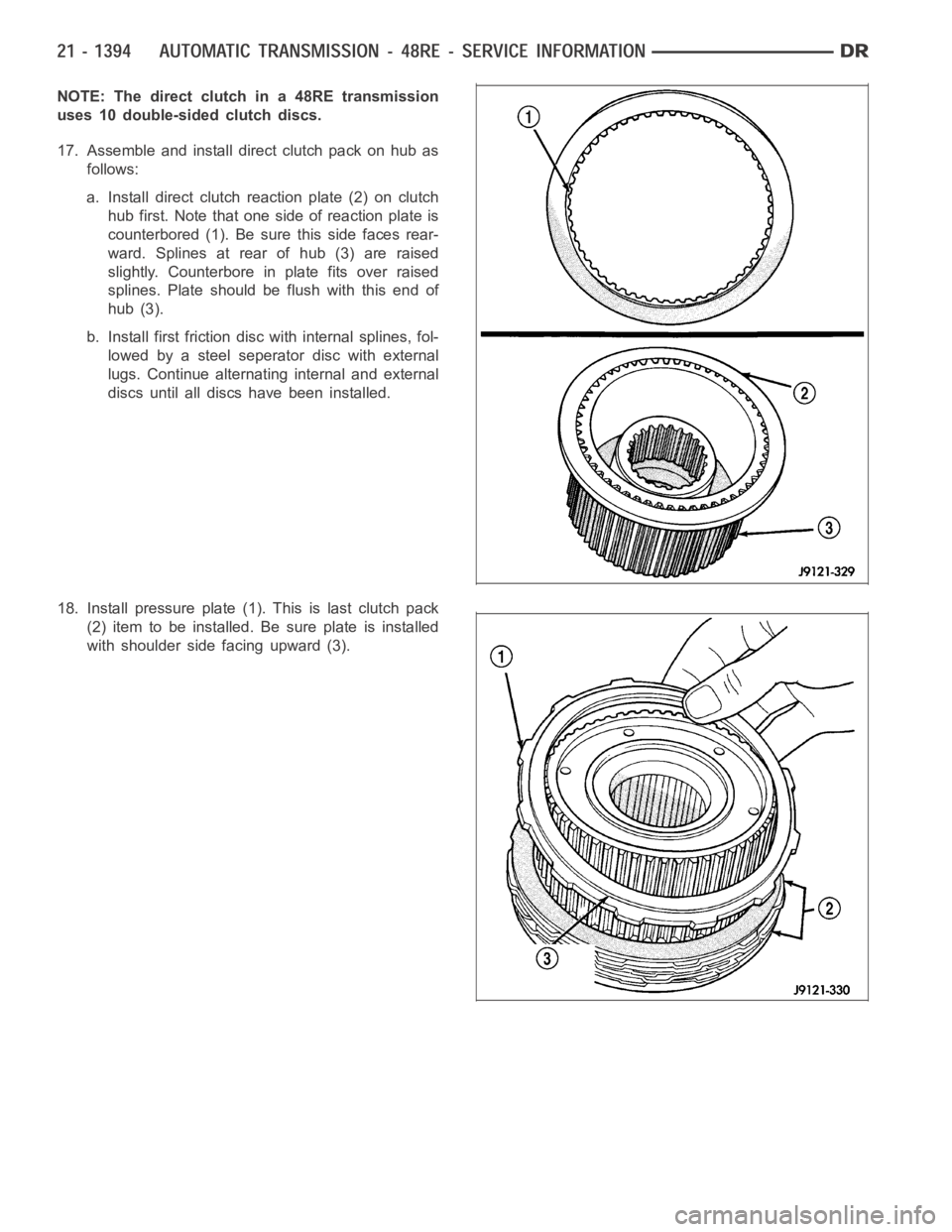
a. Install direct clutch reaction plate (2) on clutch
hub first. Note that one side of reaction plate is
counterbored (1). Be sure this side faces rear-
ward. Splines at rear of hub (3) are raised
slightly. Counterbore in plate fits over raised
splines. Plate should be flush with this end of
hub (3).
b. Install first friction disc with internal splines, fol-
lowed by a steel seperator disc with external
lugs. Continue alternating internal and external
discs until all discs have been installed.
18. Install pressure plate (1). This is last clutch pack
(2) item to be installed. Be sure plate is installed
with shoulder side facing upward (3).
Page 3938 of 5267
DISASSEMBLY
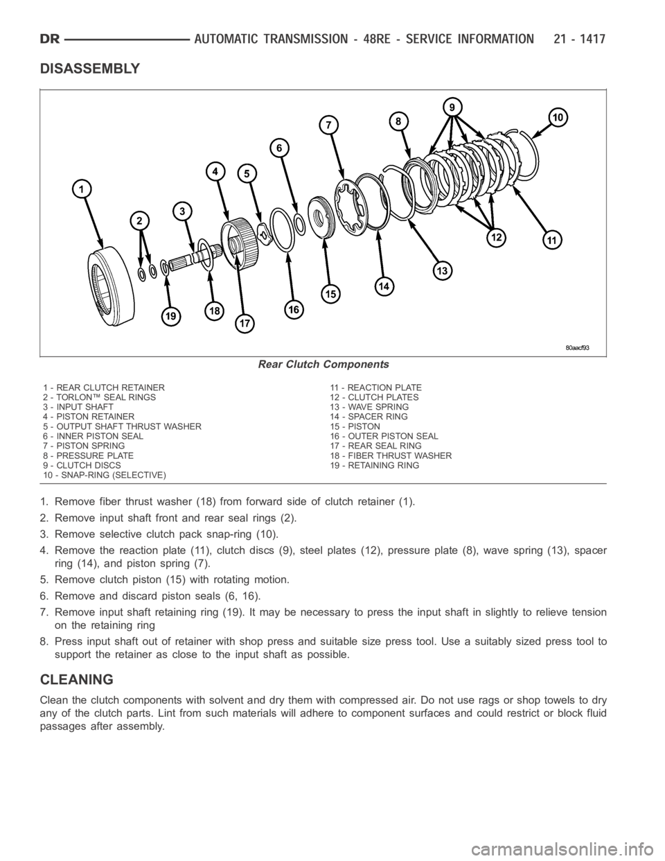
1. Remove fiber thrust washer (18) from forward side of clutch retainer (1).
2. Remove input shaft front and rear seal rings (2).
3. Remove selective clutch pack snap-ring (10).
4. Remove the reaction plate (11), clutch discs (9), steel plates (12), pressure plate (8), wave spring (13), spacer
ring (14), and piston spring (7).
5. Remove clutch piston (15) with rotating motion.
6. Remove and discard piston seals (6, 16).
7. Remove input shaft retaining ring (19). It may be necessary to press the input shaft in slightly to relieve tension
on the retaining ring
8. Press input shaft out of retainer with shop press and suitable size presstool. Use a suitably sized press tool to
support the retainer as close to the input shaft as possible.
CLEANING
Clean the clutch components with solvent and dry them with compressed air.Do not use rags or shop towels to dry
any of the clutch parts. Lint from such materials will adhere to component surfaces and could restrict or block fluid
passages after assembly.
Rear Clutch Components
1 - REAR CLUTCH RETAINER 11 - REACTION PLATE
2 - TORLON™ SEAL RINGS 12 - CLUTCH PLATES
3 - INPUT SHAFT 13 - WAVE SPRING
4 - PISTON RETAINER 14 - SPACER RING
5 - OUTPUT SHAFT THRUST WASHER 15 - PISTON
6 - INNER PISTON SEAL 16 - OUTER PISTON SEAL
7 - PISTON SPRING 17 - REAR SEAL RING
8 - PRESSURE PLATE 18 - FIBER THRUST WASHER
9 - CLUTCH DISCS 19 - RETAINING RING
10 - SNAP-RING (SELECTIVE)
Page 3940 of 5267
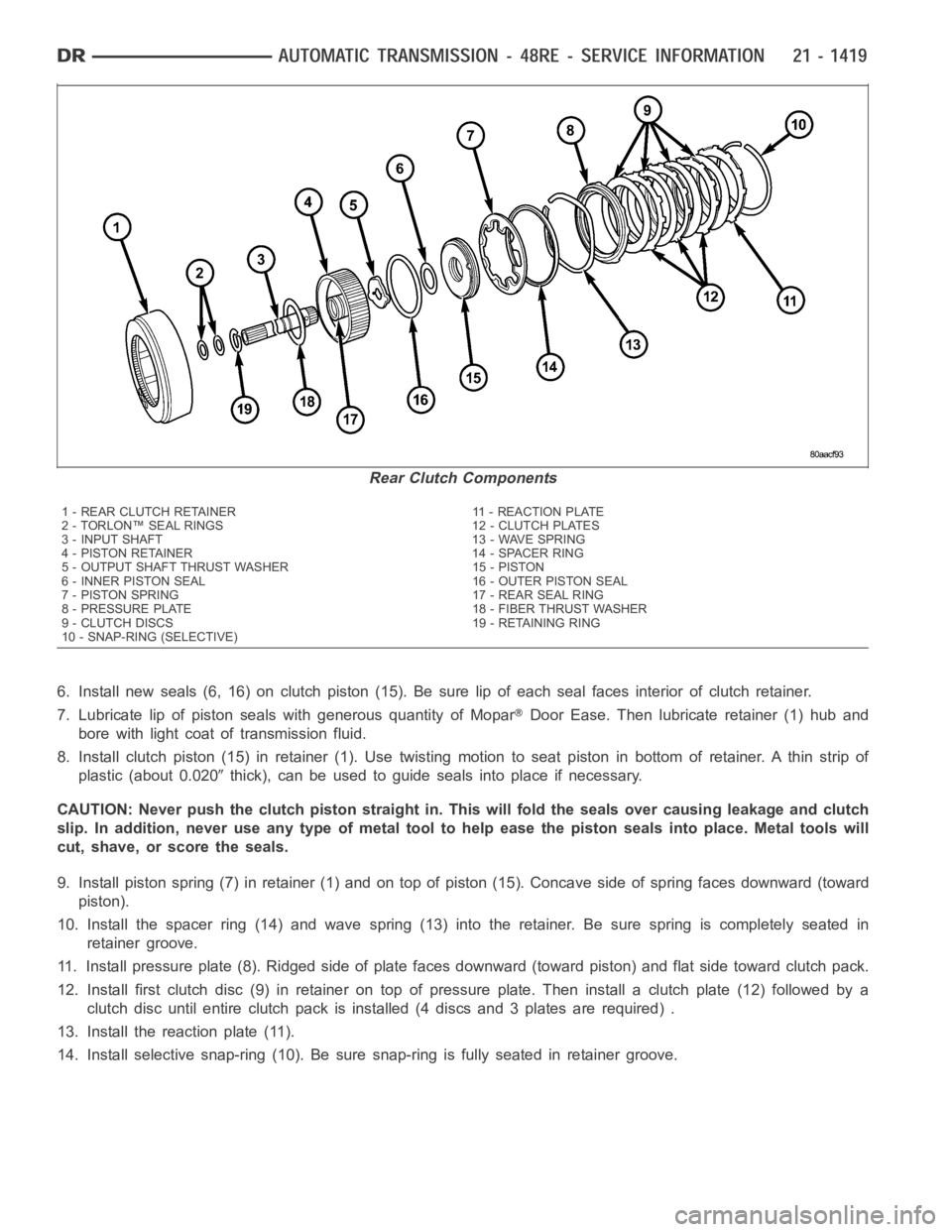
6. Install new seals (6, 16) on clutch piston (15). Be sure lip of each seal faces interior of clutch retainer.
7. Lubricate lip of piston seals with generous quantity of Mopar
Door Ease. Then lubricate retainer (1) hub and
bore with light coat of transmission fluid.
8. Install clutch piston (15) in retainer (1). Use twisting motion to seat piston in bottom of retainer. A thin strip of
plastic (about 0.020
thick), can be used to guide seals into place if necessary.
CAUTION: Never push the clutch piston straight in. This will fold the sealsover causing leakage and clutch
slip. In addition, never use any type of metal tool to help ease the piston seals into place. Metal tools will
cut, shave, or score the seals.
9. Install piston spring (7) in retainer (1) and on top of piston (15). Concave side of spring faces downward (toward
piston).
10. Install the spacer ring (14) and wave spring (13) into the retainer. Be sure spring is completely seated in
retainer groove.
11. Install pressure plate (8). Ridged side of plate faces downward (toward piston) and flat side toward clutch pack.
12. Install first clutch disc (9) in retainer on top of pressure plate. Theninstall a clutch plate (12) followed by a
clutch disc until entire clutch pack is installed (4 discs and 3 plates are required) .
13. Install the reaction plate (11).
14. Install selective snap-ring (10). Be sure snap-ring is fully seated inretainer groove.
Rear Clutch Components
1 - REAR CLUTCH RETAINER 11 - REACTION PLATE
2 - TORLON™ SEAL RINGS 12 - CLUTCH PLATES
3 - INPUT SHAFT 13 - WAVE SPRING
4 - PISTON RETAINER 14 - SPACER RING
5 - OUTPUT SHAFT THRUST WASHER 15 - PISTON
6 - INNER PISTON SEAL 16 - OUTER PISTON SEAL
7 - PISTON SPRING 17 - REAR SEAL RING
8 - PRESSURE PLATE 18 - FIBER THRUST WASHER
9 - CLUTCH DISCS 19 - RETAINING RING
10 - SNAP-RING (SELECTIVE)
Page 3950 of 5267
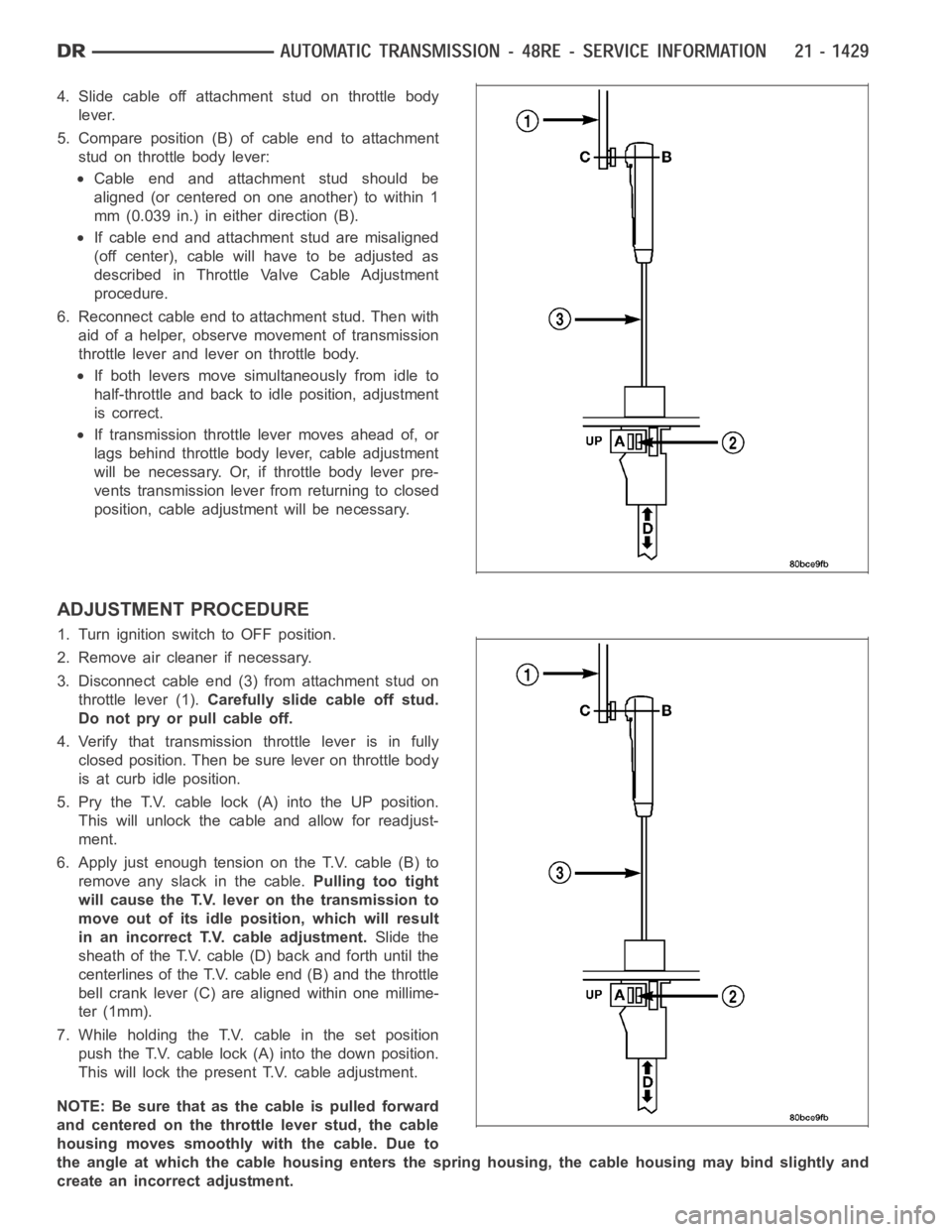
4. Slide cable off attachment stud on throttle body
lever.
5. Compare position (B) of cable end to attachment
stud on throttle body lever:
Cable end and attachment stud should be
aligned (or centered on one another) to within 1
mm (0.039 in.) in either direction (B).
If cable end and attachment stud are misaligned
(off center), cable will have to be adjusted as
described in Throttle Valve Cable Adjustment
procedure.
6. Reconnect cable end to attachment stud. Then with
aid of a helper, observe movement of transmission
throttle lever and lever on throttle body.
If both levers move simultaneously from idle to
half-throttle and back to idle position, adjustment
is correct.
If transmission throttle lever moves ahead of, or
lags behind throttle body lever, cable adjustment
will be necessary. Or, if throttle body lever pre-
vents transmission lever from returning to closed
position, cable adjustment will be necessary.
ADJUSTMENT PROCEDURE
1. Turn ignition switch to OFF position.
2. Remove air cleaner if necessary.
3. Disconnect cable end (3) from attachment stud on
throttle lever (1).Carefully slide cable off stud.
Do not pry or pull cable off.
4. Verify that transmission throttle lever is in fully
closed position. Then be sure lever on throttle body
is at curb idle position.
5. Pry the T.V. cable lock (A) into the UP position.
This will unlock the cable and allow for readjust-
ment.
6. Apply just enough tension on the T.V. cable (B) to
remove any slack in the cable.Pulling too tight
will cause the T.V. lever on the transmission to
move out of its idle position, which will result
in an incorrect T.V. cable adjustment.Slide the
sheath of the T.V. cable (D) back and forth until the
centerlines of the T.V. cable end (B) and the throttle
bell crank lever (C) are aligned within one millime-
ter (1mm).
7. While holding the T.V. cable in the set position
push the T.V. cable lock (A) into the down position.
This will lock the present T.V. cable adjustment.
NOTE:Besurethatasthecableispulledforward
and centered on the throttle lever stud, the cable
housing moves smoothly with the cable. Due to
the angle at which the cable housing enters the spring housing, the cable housing may bind slightly and
create an incorrect adjustment.
Page 3956 of 5267
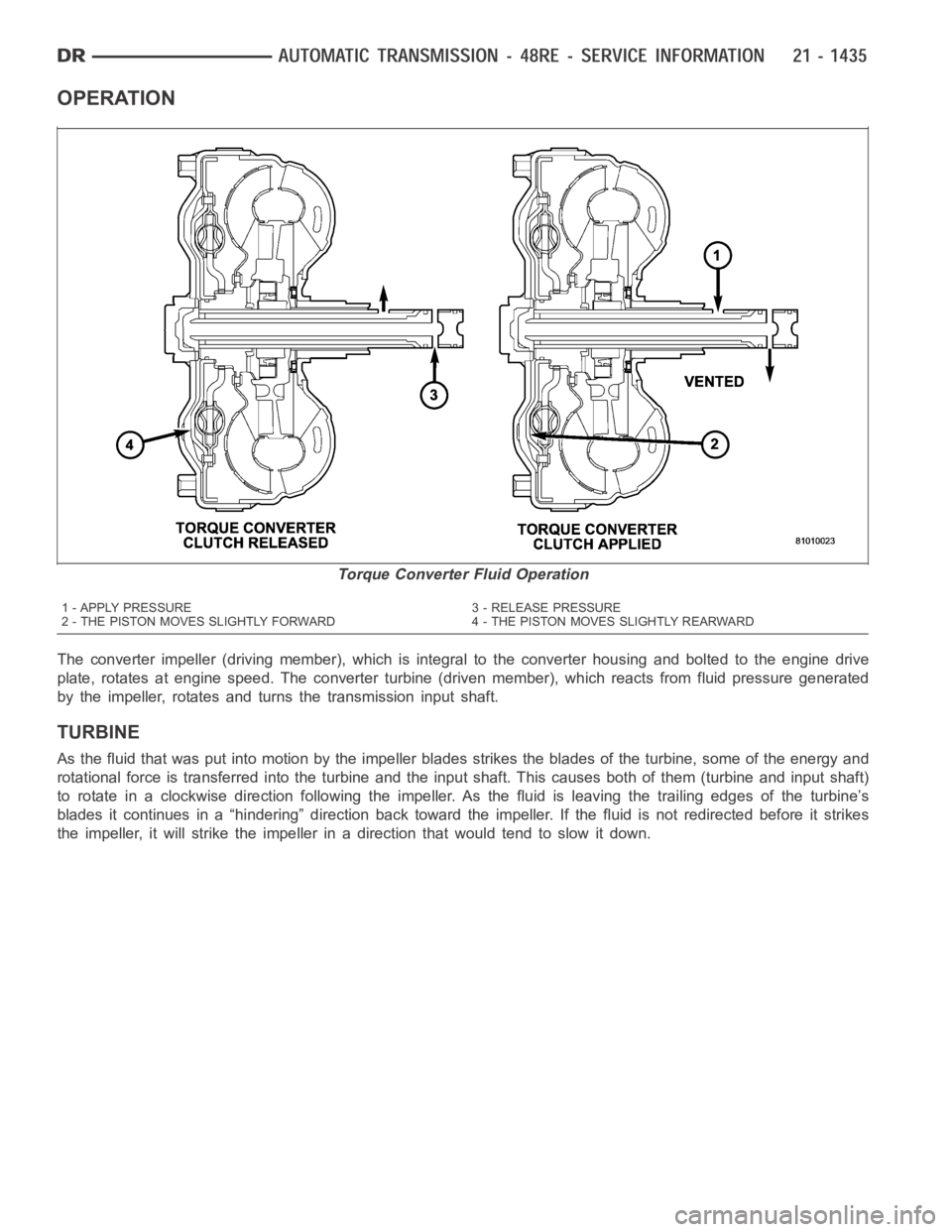
OPERATION
The converter impeller (driving member), which is integral to the converter housing and bolted to the engine drive
plate, rotates at engine speed. The converter turbine (driven member), which reacts from fluid pressure generated
by the impeller, rotates and turns the transmission input shaft.
TURBINE
As the fluid that was put into motion bythe impeller blades strikes the blades of the turbine, some of the energy and
rotational force is transferred into the turbine and the input shaft. Thiscauses both of them (turbine and input shaft)
to rotate in a clockwise direction following the impeller. As the fluid is leaving the trailing edges of the turbine’s
blades it continues in a “hindering” direction back toward the impeller. If the fluid is not redirected before it strikes
the impeller, it will strike the impeller in a direction that would tend to slow it down.
Torque Converter Fluid Operation
1 - APPLY PRESSURE 3 - RELEASE PRESSURE
2 - THE PISTON MOVES SLIGHTLY FORWARD 4 - THE PISTON MOVES SLIGHTLY REARWARD
Page 3961 of 5267
SWITCH-TOW/HAUL OVERDRIVE
DESCRIPTION
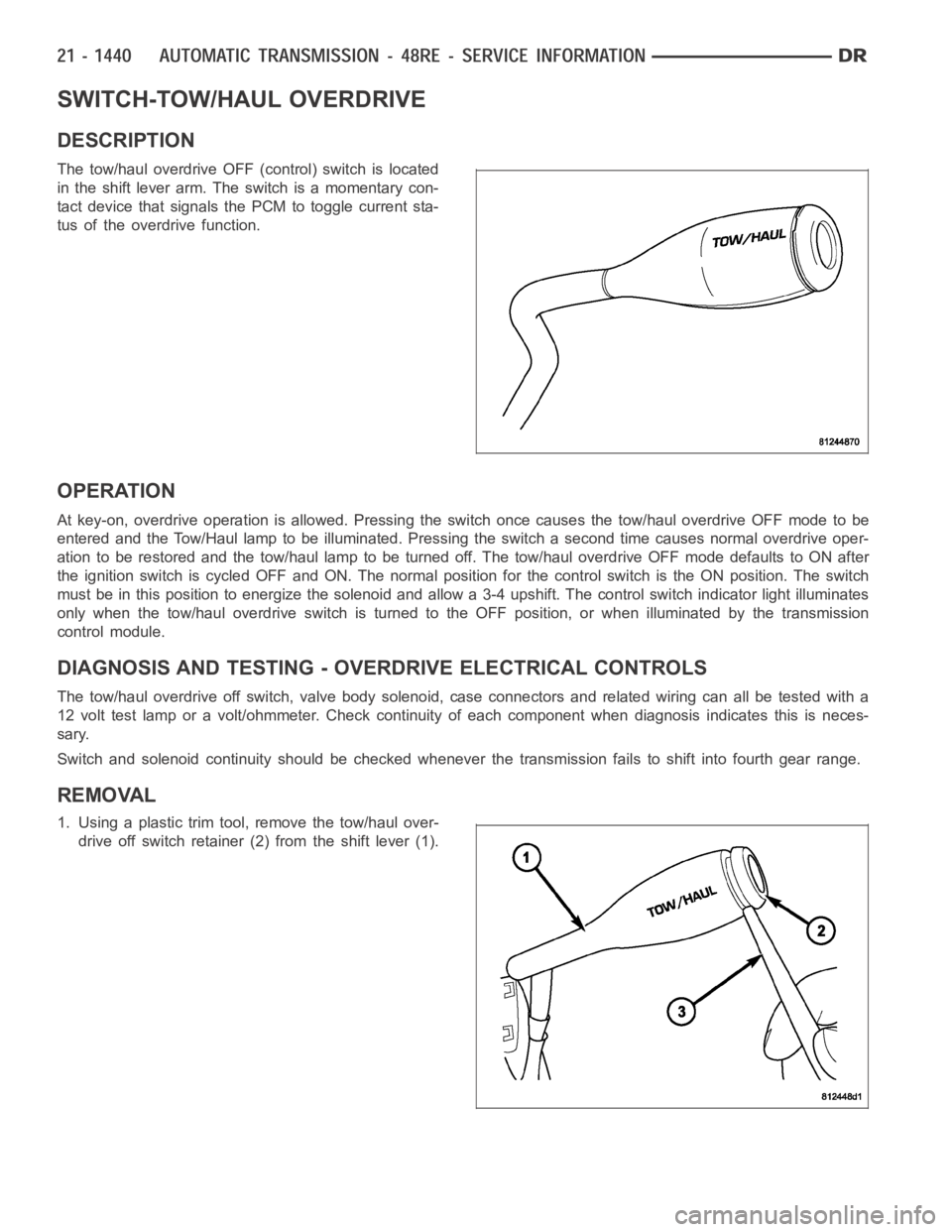
The tow/haul overdrive OFF (control) switch is located
in the shift lever arm. The switch is a momentary con-
tact device that signals the PCM to toggle current sta-
tus of the overdrive function.
OPERATION
At key-on, overdrive operation is allowed. Pressing the switch once causes the tow/haul overdrive OFF mode to be
entered and the Tow/Haul lamp to be illuminated. Pressing the switch a second time causes normal overdrive oper-
ationtoberestoredandthetow/haullamptobeturnedoff.Thetow/hauloverdrive OFF mode defaults to ON after
the ignition switch is cycled OFF and ON. The normal position for the control switch is the ON position. The switch
must be in this position to energize the solenoid and allow a 3-4 upshift. The control switch indicator light illuminates
only when the tow/haul overdrive switch is turned to the OFF position, or when illuminated by the transmission
control module.
DIAGNOSIS AND TESTING - OVERDRIVE ELECTRICAL CONTROLS
The tow/haul overdrive off switch, valve body solenoid, case connectors and related wiring can all be tested with a
12 volt test lamp or a volt/ohmmeter. Check continuity of each component when diagnosis indicates this is neces-
sary.
Switch and solenoid continuity shouldbe checked whenever the transmission fails to shift into fourth gear range.
REMOVAL
1. Using a plastic trim tool, remove the tow/haul over-
drive off switch retainer (2) from the shift lever (1).