Page 4555 of 5267
BASECOAT/CLEARCOAT FINISH
DESCRIPTION
The original equipment paint finish is a multi step process that involves cleaning, applying electro de-position
(E-coat), anti-chip primer, basecoat, and clearcoat steps.
CAUTION: Do not use abrasive chemicals, abrasive compounds or harsh alkaline based cleaning solvents
on the painted surfaces of a vehicle. Failure to follow this caution can result in damage to vehicle finish.
On most vehicles a two-part paint application (basecoat/clearcoat) is used. Color paint that is applied to primer is
called basecoat. A clear coat paint is then applied to protect the basecoatfrom ultraviolet light and to provide a
durable high-gloss finish.
Page 4556 of 5267
PA I N T T O U C H - U P
DESCRIPTION
If the painted metal surface of a vehicle becomes scratched or chipped, it should be touched-up as soon as pos-
sible to avoid corrosion.
WARNING: Use an OSHA approved respirator and safety glasses when sprayingpaint or solvents in a con-
fined area. Failure to follow this warning may result in possible personalinjury or death.
When repairing painted metal surfaces, for best results, use MOPAR
Scratch Filler/Primer, Touch-Up Paints and
Clear Top Coat (Refer to VEHICLE DATA/VEHICLE INFORMATION/BODY CODE PLATE - DESCRIPTION) for
Body Code Plate information.
STANDARD PROCEDURE
PA I N T T O U C H - U P
1. Scrape any loose paint and corrosion from inside the scratch or chip.
WARNING: Avoid prolonged skin contact with petroleum or alcohol–based cleaning solvents. Failure to fol-
low this warning can result in possible personal injury or death.
2. Clean affected area with MOPAR
Tar/Road Oil Remover or equivalent, and allow to dry.
3. Fill the inside of the scratch or chip with a coat of filler/primer. Do notoverlap primer onto good surface finish.
The applicator brush should be wet enough to puddle-fill the scratch or chip without running. Do not stroke brush
applicator on body surface. Allow the filler/primer to dry hard.
4. Cover the filler/primer with color touch-up paint. Do not overlap touch-up color onto the original color coat around
the scratch or chip. Butt the new color to the original color, if possible. Do not stroke applicator brush on body
surface. Allow touch-up paint to dry hard.
5. On vehicles without clearcoat, the touch-up color can be lightly finesse sanded (1500 grit) and polished with
rubbing compound.
6. On vehicles with clearcoat, apply clear top coat to touch-up paint with the same technique as described in Step
4. Allow clear top coat to dry hard. If desired, the clearcoat can be lightlyfinesse sanded (1500 grit) and polished
with rubbing compound.
Page 4557 of 5267
FINESSE SANDING/BUFFING AND POLISHING
DESCRIPTION
CAUTION: Do not remove more than 0.5 mils of clearcoat finish when sanding,hand buffing or polishing.
Basecoat paint must retain clearcoat for durability.
CAUTION: If the finish has been finesse sanded in the past, it cannot be repeated. Failure to follow this
caution can result in damage to vehicle finish.
NOTE: Finesse sanding should only be performed by a trained automotive paint technician.
Minor acid etching, orange peel, or smudging in a clearcoat or single-stage finish can be reduced with light finesse
sanding, hand buffing and polishing. Use a Paint Thickness Gauge #PR-ETG-2X or equivalent to determine
clearcoat or single-stage paint thickness before and after the repair.
Page 4603 of 5267
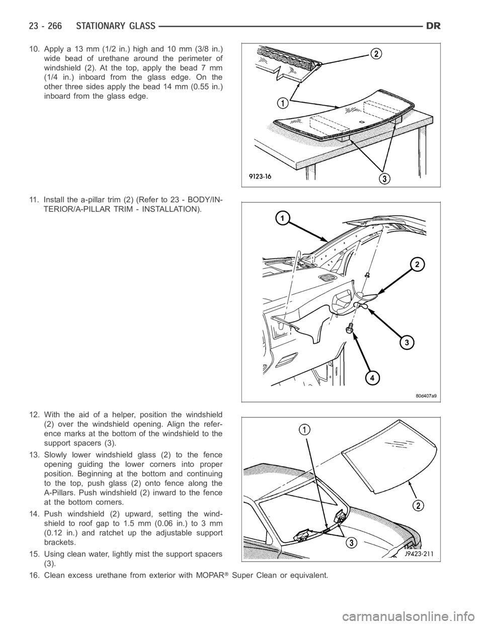
10. Apply a 13 mm (1/2 in.) high and 10 mm (3/8 in.)
wide bead of urethane around the perimeter of
windshield(2).Atthetop,applythebead7mm
(1/4 in.) inboard from the glass edge. On the
other three sides apply the bead 14 mm (0.55 in.)
inboard from the glass edge.
11. Install the a-pillar trim (2) (Refer to 23 - BODY/IN-
TERIOR/A-PILLAR TRIM - INSTALLATION).
12. With the aid of a helper, position the windshield
(2) over the windshield opening. Align the refer-
ence marks at the bottom of the windshield to the
support spacers (3).
13. Slowly lower windshield glass (2) to the fence
opening guiding the lower corners into proper
position. Beginning at the bottom and continuing
to the top, push glass (2) onto fence along the
A-Pillars. Push windshield (2) inward to the fence
at the bottom corners.
14. Push windshield (2) upward, setting the wind-
shieldtoroofgapto1.5mm(0.06in.)to3mm
(0.12 in.) and ratchet up the adjustable support
brackets.
15. Using clean water, lightly mist the support spacers
(3).
16. Clean excess urethane from exterior with MOPAR
Super Clean or equivalent.
Page 4610 of 5267
The motor/module is programmed to learn the speed required to drive the panel based on position and recalibrates
itself as needed. If the sunroof becomes uncalibrated, it will only respond to the vent switch. If the vent switch is
pressed, the glass will move toward vent; if the switch is released, all motion stops. In the event that the sunroof
system becomes uncalibrated performthe sunroof position calibration procedure, (Refer to 8 - ELECTRICAL/
POWER TOP/MOTOR - STANDARD PROCEDURE -SUNROOF POSITION CALIBRATION).
DIAGNOSIS AND TESTING
POWER TOP - SUNROOF
Any diagnosis of the power sunroof system should begin with the use of a scantool and the proper Diagnostic
Procedures Information. The scan tool can provide confirmation that the Controller Area Network (CAN) Data Bus is
functional, that all of the electronic modules are sending and receiving the proper messages on the CAN Data Bus,
and that the power sunroof motor is being sent the proper hard wired output by the sunroof switch.
For complete circuit diagrams, refer to the appropriate wiring information. The wiring information includes wiring dia-
grams, proper wire and connector repair procedures, details of wire harness routing and retention, connector pin-out
information and location views for the various wire harness connectors, splices and grounds.
Refer to the appropriate diagnostic information.
SUNROOF
Refer to SUNROOF DIAGNOSIS CHART for possible causes. Before beginning sunroof diagnostics verify that all
other power accessories are in proper operating condition. If not, a common electrical problem may exist. Refer to
Wiring Diagrams, in this publication for circuit, splice and component descriptions. Check the condition of the circuit
protection (20 amp circuit breaker in the Junction Block). Inspect all wiring connector pins for proper engagement
and continuity. Check for battery voltage at the power sunroof controller, refer to Wiring Diagrams, for circuit infor-
mation. If battery voltage of more than 10 volts is detected at the controller, proceed with the following tests (the
controller will not operate at less than 10 volts).
Before beginning diagnosis for wind noise or water leaks, verify that the problem was not caused by releasing the
control switch before the sunroof was fully closed. The sunroof module hasa water-management system. If how-
ever, the sunroof glass is in a partial closed position, high pressure water may be forced beyond the water man-
agement system boundariesand onto the headlining.
Every time the sunroof module loses power it must be initialized. This is done by connecting power to the sunroof
and moving the sunroof toward the closed position. When initialization occurs a slight “kick” in the sunroof module
will be seen and heard. This is the indication that the sunroof module is initialized
SUNROOF DIAGNOSIS CHART
SYMPTOM POSSIBLE CAUSE
Sunroof motor inoperative. Faulty control switch.
Faulty circuit ground between sunroof module, control switch,
and body harness.
Faulty power circuit between sunroof module, control switch,
and body harness.
Faulty sunroof drive motor.
Faulty sunroof module.
Audible whine when switch is depressed,
sunroof does not operate.Faulty sunroof drive motor.
Binding cable.
Audible clicking or ratcheting when switch is
pressed, sunroof does not operate.Broken or worn drive cable.
Worn drive motor gear.
Mechanisms not synchronized.
Page 4615 of 5267
INSTALLATION
WARNING: The Excessive Force Limitation (EFL) feature must be calibratedanytimeasunroofmotor/mod-
ule is replaced with a new component. Failure to perform this procedure could result in vehicle damage
and/or personal injury. (Refer to 8 - ELECTRICAL/POWER TOP/MOTOR - STANDARD PROCEDURE - EXCES-
SIVE FORCE LIMITATION (EFL) CALIBRATION) for the appropriate procedure.
1. Verify that glass panel is loose and slightly retracted.
2. Raise sunroof module assembly (1) and guide it carefully into position.
3. Hand start the eight screws (2).
4. Line up the locating holes and tighten the attaching screws (2) to 9 Nꞏm (80in.lbs.).
5. Connect the electrical connector (1).
Page 4693 of 5267
INSTALLATION
WARNING: Always keep hands and clothing clear
of the wire rope, hook and fairlead opening during
operation and when spooling. Failure to follow
these instructions may result in personal injury or
death.
CAUTION: Wire rope must spool on the winch
drum in the direction indicated.
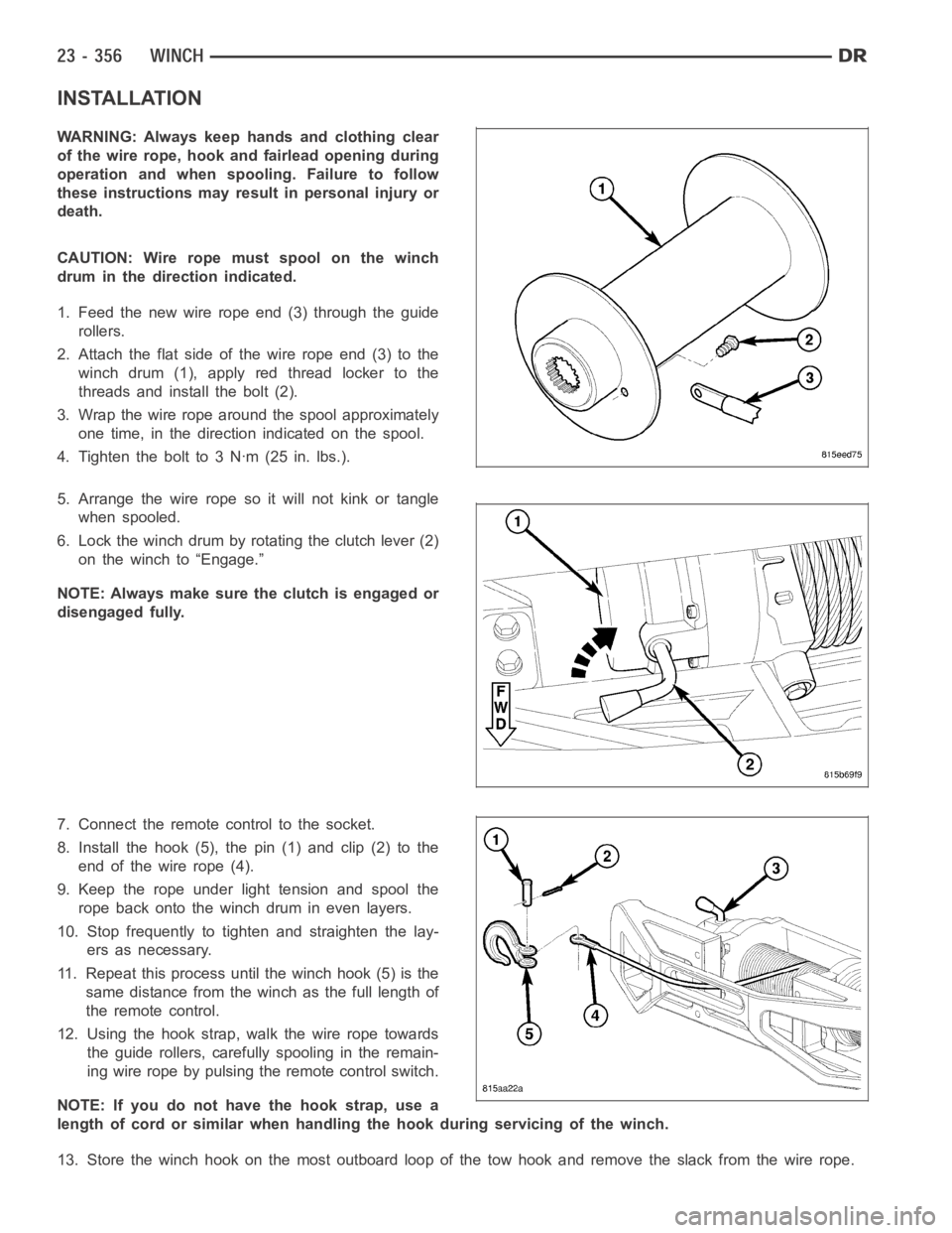
1. Feed the new wire rope end (3) through the guide
rollers.
2. Attach the flat side of the wire rope end (3) to the
winch drum (1), apply red thread locker to the
threads and install the bolt (2).
3. Wrap the wire rope around the spool approximately
one time, in the direction indicated on the spool.
4. Tighten the bolt to 3 Nꞏm (25 in. lbs.).
5. Arrange the wire rope so it will not kink or tangle
when spooled.
6. Lock the winch drum by rotating the clutch lever (2)
on the winch to “Engage.”
NOTE: Always make sure the clutch is engaged or
disengaged fully.
7. Connect the remote control to the socket.
8. Install the hook (5), the pin (1) and clip (2) to the
end of the wire rope (4).
9. Keep the rope under light tension and spool the
rope back onto the winch drum in even layers.
10. Stop frequently to tighten and straighten the lay-
ers as necessary.
11. Repeat this process until the winch hook (5) is the
same distance from the winch as the full length of
theremotecontrol.
12. Using the hook strap, walk the wire rope towards
the guide rollers, carefully spooling in the remain-
ing wire rope by pulsing the remote control switch.
NOTE: If you do not have the hook strap, use a
length of cord or similar when handling the hook during servicing of the winch.
13. Store the winch hook on the most outboard loop of the tow hook and remove the slack from the wire rope.
Page 4877 of 5267
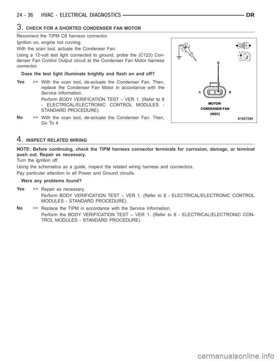
3.CHECK FOR A SHORTED CONDENSER FAN MOTOR
Reconnect the TIPM C8 harness connector.
Ignition on, engine not running.
With the scan tool, actuate the Condenser Fan.
Using a 12-volt test light connected to ground, probe the (C123) Con-
denser Fan Control Output circuit at the Condenser Fan Motor harness
connector.
Does the test light illuminate brightly and flash on and off?
Ye s>>
With the scan tool, de-actuate the Condenser Fan. Then,
replace the Condenser Fan Motor in accordance with the
Service Information.
Perform BODY VERIFICATION TEST – VER 1. (Refer to 8
- ELECTRICAL/ELECTRONIC CONTROL MODULES -
STANDARD PROCEDURE).
No>>
With the scan tool, de-actuate the Condenser Fan. Then,
Go To 4
4.INSPECT RELATED WIRING
NOTE: Before continuing, check the TIPM harness connector terminals for corrosion, damage, or terminal
push out. Repair as necessary.
Turn the ignition off.
Using the schematics as a guide, inspect the related wiring harness and connectors.
Pay particular attention to all Power and Ground circuits.
Were any problems found?
Ye s>>
Repair as necessary.
Perform BODY VERIFICATION TEST – VER 1. (Refer to 8 - ELECTRICAL/ELECTRONIC CONTROL
MODULES - STANDARD PROCEDURE).
No>>
Replace the TIPM in accordance with the Service Information.
Perform the BODY VERIFICATION TEST – VER 1. (Refer to 8 - ELECTRICAL/ELECTRONIC CON-
TROL MODULES - STANDARD PROCEDURE)