2006 DODGE RAM SRT-10 light
[x] Cancel search: lightPage 5044 of 5267
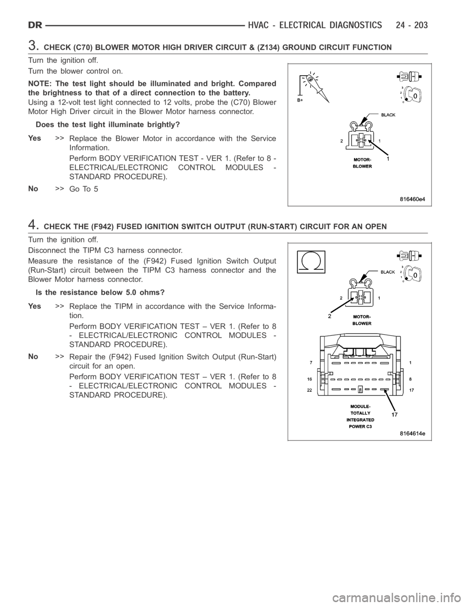
3.CHECK (C70) BLOWER MOTOR HIGH DRIVER CIRCUIT & (Z134) GROUND CIRCUIT FUNCTION
Turn the ignition off.
Turn the blower control on.
NOTE: The test light should be illuminated and bright. Compared
the brightness to that of a direct connection to the battery.
Using a 12-volt test light connected to 12 volts, probe the (C70) Blower
Motor High Driver circuit in the Blower Motor harness connector.
Does the test light illuminate brightly?
Ye s>>
Replace the Blower Motor in accordance with the Service
Information.
Perform BODY VERIFICATION TEST - VER 1. (Refer to 8 -
ELECTRICAL/ELECTRONIC CONTROL MODULES -
STANDARD PROCEDURE).
No>>
Go To 5
4.CHECK THE (F942) FUSED IGNITION SWITCH OUTPUT (RUN-START) CIRCUIT FOR AN OPEN
Turn the ignition off.
Disconnect the TIPM C3 harness connector.
Measure the resistance of the (F942) Fused Ignition Switch Output
(Run-Start) circuit between the TIPM C3 harness connector and the
Blower Motor harness connector.
Is the resistance below 5.0 ohms?
Ye s>>
Replace the TIPM in accordance with the Service Informa-
tion.
Perform BODY VERIFICATION TEST – VER 1. (Refer to 8
- ELECTRICAL/ELECTRONIC CONTROL MODULES -
STANDARD PROCEDURE).
No>>
Repair the (F942) Fused Ignition Switch Output (Run-Start)
circuit for an open.
Perform BODY VERIFICATION TEST – VER 1. (Refer to 8
- ELECTRICAL/ELECTRONIC CONTROL MODULES -
STANDARD PROCEDURE).
Page 5052 of 5267
DIAGNOSIS AND TESTING
HEATING-A/C SYSTEM DIAGNOSTICS
CAUTION: Do not exchange A/C Heater Controls from vehicle to vehicle. Software versions differ between
models and model years. Installing an A/C Heater Control with software that is incompatible for a given
vehicle can result in either improper or failed HVAC system operation.
ON-BOARD DIAGNOSTICS
The A/C-heater control communicates on the controller area network (CAN)B bus and is fully addressable with a
scan tool.
The A/C-heater control’s primary means of fault detection is through active and stored diagnostic trouble codes
(DTCs). Active DTCs are those which currently exist in the system. The condition causing the fault must be repaired
in order to clear this type of DTC. Stored DTCs are those which occurred in the system since the A/C-heater control
received the last clear diagnostic info message. DTCs must be read with a scan tool. Refer to 24 - HVAC - Elec-
trical Diagnostics for HVAC DTC diagnostic test procedures.
The A/C-heater control’s secondary means of fault detection is through system tests. These tests include the HVAC
System Test, the A/C Cooldown Test, Actuator Calibration, and Actuator DTC Detection. Refer to System Tests in
this Section for a detailed description of each test.
SYSTEM TESTS
HVAC System Test
The HVAC System Test, found in 24 - HVAC - Electrical Diagnostics, providesa starting point in the diagnostic
process by identifying the appropriate diagnostic procedure or system test to perform when diagnosing a given
symptom, condition, or DTC. It also provides a means for testing the entireHVAC system by utilizing the A/C-heater
control’s On-Board System Tests. The On-Board System Tests can also assistindiagnosingstoredDTCs.
A/CCOOLDOWNTEST
The A/C Cooldown Test:
is actuated with a scan tool.
tests A/C system performance based on evaporator temperature sensor input.
will fail if evaporator temperature isbelow 13°C (55°F) when initiating the test.
will pass if the evaporator temperature drops 11°C (20°F).
indicates an outcome by displaying one or more test status messages on the scan tool. These test status
messages will clear after paging back out of this test function. Therefore, is it important to note all of the mes-
sages before doing so.
will cause the A/C status indicator to flash while the test is running.
ACTUATOR CALIBRATION FUNCTION
The Actuator Calibration function:
is actuated with a scan tool.
clears all actuator related DTCs when the test is actuated.
homes and repositions door actuators.
monitors for door span faults. Door span faults (XXX Door Travel Range Too Large or XXX Door Travel Range
Too Small) will only display after calibration.
will cause the electric backlight (EBL) status indicator (if equipped) toflash while the test is running.
Page 5055 of 5267
Condition Possible Causes Correction
2. Faulty fuse.2. Check the fuse in the junction block. Repair the
shorted circuit or component and replace the fuse,
if required.
3. Faulty A/C compressor
clutch field coil.3. See A/C Compressor Clutch Field Coil in this
group. Test the compressor clutch field coil and
replace, if required.
4. Improperly installed or
faulty Evaporator
Temperature Sensor.4. See Evaporator Temperature Sensor in this
group. Correctly install or replace the sensor as
required.
5. Faulty A/C pressure
transducer.5. See A/C pressure transducer in this group. Test
the transducer and replace, if required.
6. Faulty A/C-heater control,
totally integrated power
module (TIPM), gateway
module or PCM/ECM.6. Refer to the appropriate Electrical Diagnostic
Procedures for testing of the A/C-heater control,
TIPM, gateway module or PCM/ECM. Test the
module and replace, if required.
Normal pressures, but A/C
Performance Test air
temperatures at center panel
outlet are too high.1. Excessive refrigerant oil in
system.1. See Refrigerant Oil Level in this group. Recover
the refrigerant from the refrigerant system and
inspect the refrigerant oil content. Restore the
refrigerant oil to the proper level, if required.
2. Blend door inoperative or
sealing improperly.2. See Blend Door in this group. Inspect the blend
door for proper operation and sealing and correct,
if required.
3. Blend door actuator faulty
or inoperative.3. Perform blend door actuator diagnosis, replace
if faulty.
The low side pressure is
normal or slightly low, and
the high side pressure is too
low.1. Low refrigerant system
charge.1. See Refrigerant System Leaks in this group.
Test the refrigerant system for leaks. Repair,
evacuate and charge the refrigerant system, if
required.
2. Refrigerant flow through
the accumulator is restricted.2. See Accumulator in this group. Replace the
restricted accumulator, if required.
3. Refrigerant flow through
the evaporator coil is
restricted.3. See A/C Evaporator in this group. Replace the
restricted evaporator coil, if required.
4. Faulty compressor.4. See A/C Compressor in this group. Replace the
compressor, if required.
The low side pressure is
normal or slightly high, and
the high side pressure is too
high.1. Condenser air flow
restricted.1. Check the A/C condenser for damaged fins,
foreign objects obstructing air flow through the
condenser fins, and missing or improperly
installed air seals. Refer to Cooling for more
information on air seals. Clean, repair, or replace
components as required.
2. Inoperative cooling fan.2. Refer to Cooling for more information. Test the
cooling fan and replace, if required.
3. Refrigerant system
overcharged.3. See Refrigerant System Charge in this group.
Recover the refrigerant from the refrigerant
system. Charge the refrigerant system to the
proper level, if required.
4. Air in the refrigerant
system.4. See Refrigerant System Leaks in this group.
Test the refrigerant system for leaks. Repair,
evacuate and charge the refrigerant system, if
required.
Page 5056 of 5267
Condition Possible Causes Correction
5. Engine overheating.5. Refer to Cooling for more information. Test the
cooling system and repair, if required.
The low side pressure is too
high, and the high side
pressure is too low.1. Accessory drive belt
slipping.1. Refer to Cooling for more information. Inspect
the accessory drive belt condition and tension.
Tighten or replace the accessory drive belt, if
required.
2. Fixed orifice tube not
installed.2. See A/C Orifice Tube in this group. Replace the
liquid line, if required.
3. Faulty A/C compressor.3. See A/C Compressor in this group. Replace the
compressor, if required.
The low side pressure is too
low, and the high side
pressure is too high.1. Restricted refrigerant flow
through the refrigerant lines.1. See Liquid, Suction, and Discharge Line in this
group. Inspect the refrigerant lines for kinks, tight
bends or improper routing. Correct the routing or
replace the refrigerant line, if required.
2. Restricted refrigerant flow
through the fixed orifice
tube.2. See A/C Orifice Tube in this group. Replace the
liquid line, if required.
3. Restricted refrigerant flow
through the condenser.3. See A/C Condenser in this group. Replace the
restricted condenser, if required.
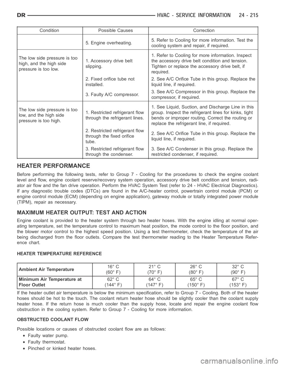
HEATER PERFORMANCE
Before performing the following tests, refer to Group 7 - Cooling for the procedures to check the engine coolant
level and flow, engine coolant reserve/recovery system operation, accessory drive belt condition and tension, radi-
ator air flow and the fan drive operation. Perform the HVAC System Test (refer to 24 - HVAC Electrical Diagnostics).
If any diagnostic trouble codes (DTCs) are found in the A/C-heater control, powertrain control module (PCM) or
engine control module (ECM) (depending on engine application), gateway module or totally integrated power module
(TIPM), repair as necessary.
MAXIMUM HEATER OUTPUT: TEST AND ACTION
Engine coolant is provided to the heater system through two heater hoses. With the engine idling at normal oper-
ating temperature, set the temperature control to maximum heat position,the mode control to the floor position, and
the blower motor control to the highest speed position. Using a test thermometer, check the temperature of the air
being discharged from the floor outlets. Compare the test thermometer reading to the Heater Temperature Refer-
ence chart.
HEATER TEMPERATURE REFERENCE
Ambient Air Temperature16° C
(60° F)21° C
(70° F)26° C
(80° F)32° C
(90° F)
Minimum Air Temperature at
Floor Outlet62° C
(144° F)64° C
(147° F)65° C
(150° F)67° C
(153° F)
If the heater outlet air temperature is below the minimum specification, refer to Group 7 - Cooling. Both of the heater
hoses should be hot to the touch. The coolant return heater hose should be slightly cooler than the coolant supply
heater hose. If the return hose is much cooler than the supply hose, locate and repair the engine coolant flow
obstruction in the cooling system. RefertoGroup7-Coolingformoreinformation.
OBSTRUCTED COOLANT FLOW
Possible locations or causes of obstructed coolant flow are as follows:
Faulty water pump.
Faulty thermostat.
Pinched or kinked heater hoses.
Page 5064 of 5267
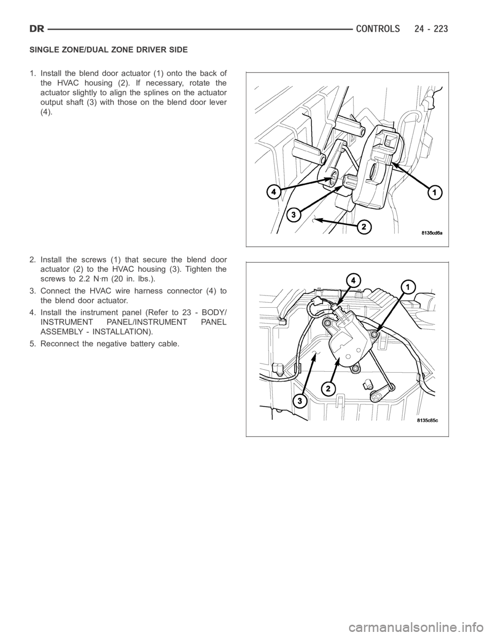
SINGLE ZONE/DUAL ZONE DRIVER SIDE
1. Install the blend door actuator (1) onto the back of
the HVAC housing (2). If necessary, rotate the
actuator slightly to align the splines on the actuator
output shaft (3) with those on the blend door lever
(4).
2. Install the screws (1) that secure the blend door
actuator (2) to the HVAC housing (3). Tighten the
screws to 2.2 Nꞏm (20 in. lbs.).
3. Connect the HVAC wire harness connector (4) to
the blend door actuator.
4. Install the instrument panel (Refer to 23 - BODY/
INSTRUMENT PANEL/INSTRUMENT PANEL
ASSEMBLY - INSTALLATION).
5. Reconnect the negative battery cable.
Page 5068 of 5267
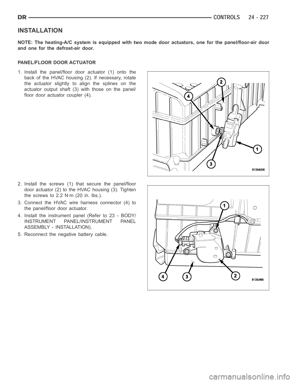
INSTALLATION
NOTE: The heating-A/C system is equipped with two mode door actuators, onefor the panel/floor-air door
and one for the defrost-air door.
PANEL/FLOOR DOOR ACTUATOR
1. Install the panel/floor door actuator (1) onto the
back of the HVAC housing (2). If necessary, rotate
the actuator slightly to align the splines on the
actuator output shaft (3) with those on the panel/
floor door actuator coupler (4).
2. Install the screws (1) that secure the panel/floor
door actuator (2) to the HVAC housing (3). Tighten
the screws to 2.2 Nꞏm (20 in. lbs.).
3. Connect the HVAC wire harness connector (4) to
the panel/floor door actuator.
4. Install the instrument panel (Refer to 23 - BODY/
INSTRUMENT PANEL/INSTRUMENT PANEL
ASSEMBLY - INSTALLATION).
5. Reconnect the negative battery cable.
Page 5069 of 5267
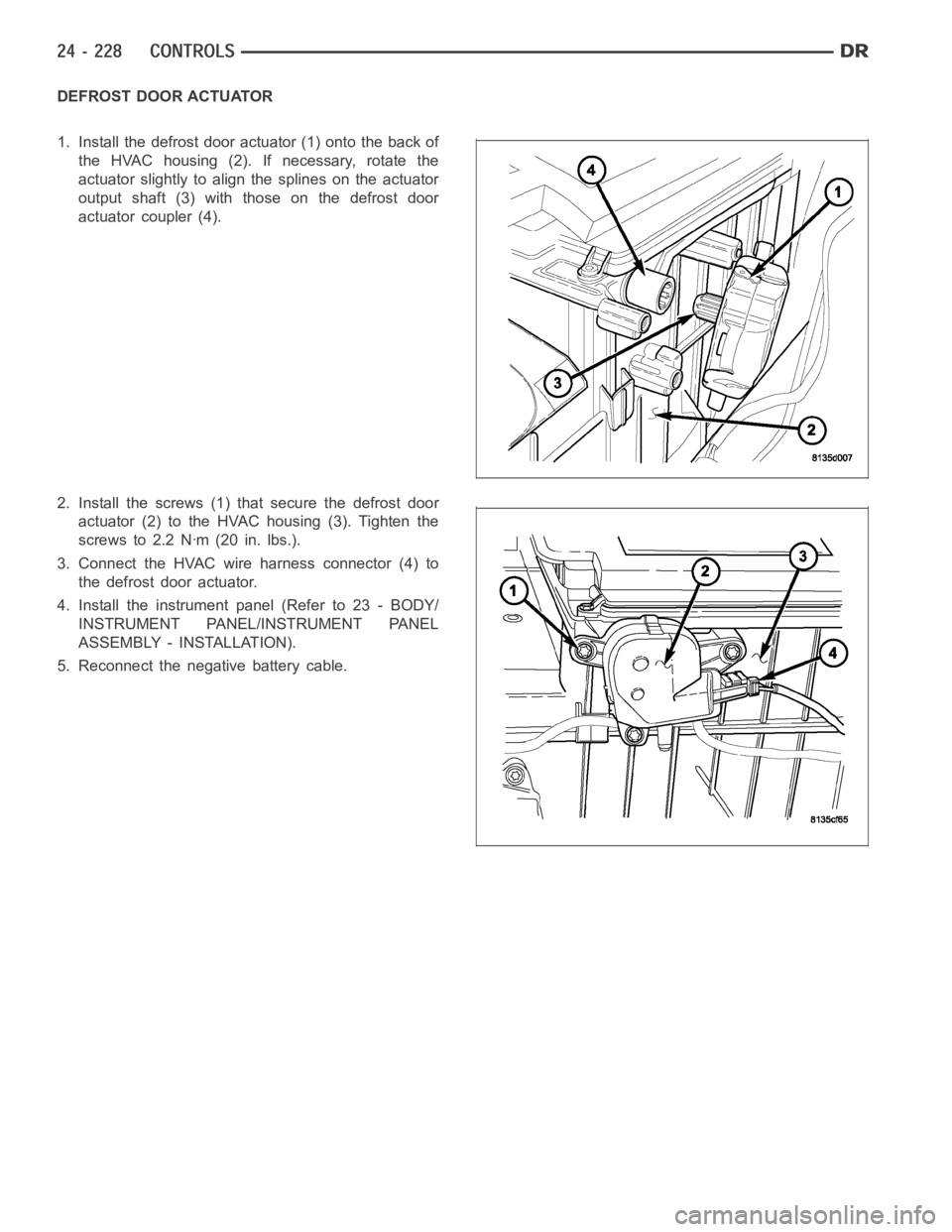
DEFROST DOOR ACTUATOR
1. Install the defrost door actuator (1) onto the back of
the HVAC housing (2). If necessary, rotate the
actuator slightly to align the splines on the actuator
output shaft (3) with those on the defrost door
actuator coupler (4).
2. Install the screws (1) that secure the defrost door
actuator (2) to the HVAC housing (3). Tighten the
screws to 2.2 Nꞏm (20 in. lbs.).
3. Connect the HVAC wire harness connector (4) to
the defrost door actuator.
4. Install the instrument panel (Refer to 23 - BODY/
INSTRUMENT PANEL/INSTRUMENT PANEL
ASSEMBLY - INSTALLATION).
5. Reconnect the negative battery cable.
Page 5071 of 5267
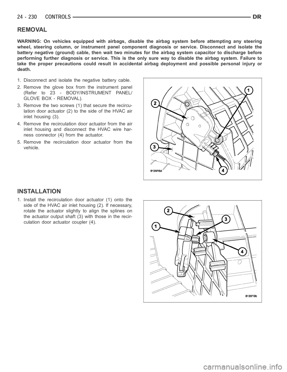
REMOVAL
WARNING: On vehicles equipped with airbags, disable the airbag system before attempting any steering
wheel, steering column, or instrument panel component diagnosis or service. Disconnect and isolate the
battery negative (ground) cable, then wait two minutes for the airbag system capacitor to discharge before
performing further diagnosis or service. This is the only sure way to disable the airbag system. Failure to
take the proper precautions could result in accidental airbag deploymentand possible personal injury or
death.
1. Disconnect and isolate the negative battery cable.
2. Remove the glove box from the instrument panel
(Refer to 23 - BODY/INSTRUMENT PANEL/
GLOVE BOX - REMOVAL).
3. Remove the two screws (1) that secure the recircu-
lation door actuator (2) to the side of the HVAC air
inlet housing (3).
4. Remove the recirculation door actuator from the air
inlet housing and disconnect the HVAC wire har-
ness connector (4) from the actuator.
5. Remove the recirculation door actuator from the
vehicle.
INSTALLATION
1. Install the recirculation door actuator (1) onto the
side of the HVAC air inlet housing (2). If necessary,
rotate the actuator slightly to align the splines on
the actuator output shaft (3) with those in the recir-
culation door actuator coupler (4).