2006 DODGE RAM SRT-10 wheel
[x] Cancel search: wheelPage 1694 of 5267
CRANKSHAFT
DESCRIPTION
The crankshaft is constructed of nodular cast iron. The crankshaft is a crosshaped four throw design with eight
counterweights for balancing purposes. The crankshaft is supported by five select fit main bearings with the number
three serving as the thrust washer location. The main journals of the crankshaft are cross drilled to improve rod
bearing lubrication. The number eight counterweight has provisions for crankshaft position sensor target wheel
mounting. The select fit main bearing markings are located on the rear sideof the target wheel. The crankshaft oil
seals are one piece design. The front oil seal is retained in the timing chain cover, and the rear seal is pressed in
to a bore formed by the cylinder block and the bedplate assembly.
REMOVAL
NOTE: To remove the crankshaft from the engine, the engine must be removed from the vehicle.
1. Remove the engine. (Refer to 9 - ENGINE - REMOVAL).
2. Remove the engine oil pump. (Refer to 9 - ENGINE/LUBRICATION/OIL PUMP - REMOVAL).
CAUTION: DO NOT pry on the oil pan gasket when removing the oil pan, The oil pan gasket is mounted to
the cylinder block in three locations and will remain attached to block when removing oil pan. Gasket can
not be removed with oil pan.
3. Remove oil pan. (Refer to 9 - ENGINE/LUBRICATION/OIL PAN - REMOVAL).
4. Remove the oil pump pickup tube and oil pan gasket /windage tray.
5. Remove the bedplate mounting bolts. Note the location of the three stud bolts for installation.
6. Remove the connecting rods from the crankshaft.
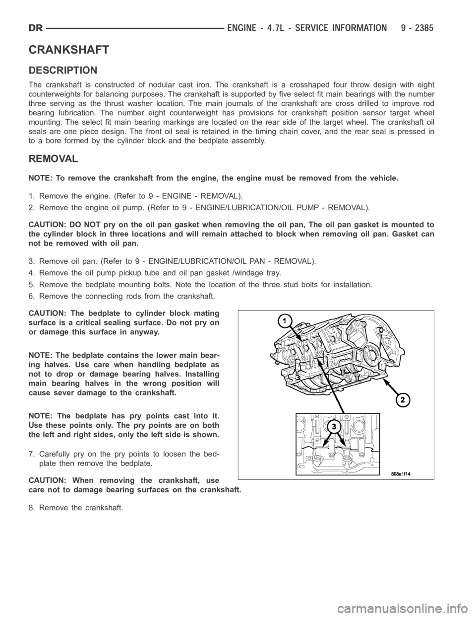
CAUTION: The bedplate to cylinder block mating
surface is a critical sealing surface. Do not pry on
or damage this surface in anyway.
NOTE: The bedplate contains the lower main bear-
ing halves. Use care when handling bedplate as
not to drop or damage bearing halves. Installing
main bearing halves in the wrong position will
cause sever damage to the crankshaft.
NOTE: The bedplate has pry points cast into it.
Use these points only. The pry points are on both
the left and right sides, only the left side is shown.
7. Carefully pry on the pry points to loosen the bed-
plate then remove the bedplate.
CAUTION: When removing the crankshaft, use
care not to damage bearing surfaces on the crankshaft.
8. Remove the crankshaft.
Page 1698 of 5267
BEARINGS - CRANKSHAFT MAIN
STANDARD PROCEDURE - CRANKSHAFT MAIN BEARING - FITTING
MAIN BEARING JOURNAL DIAMETER (CRANKSHAFT REMOVED)
Crankshaft removed from the cylinder block.
Clean the oil off the main bearing journal.
Determine the maximum diameter of the journal with a micrometer. Measure at two locations 90° apart at each end
of the journal.
The maximum allowable taper is 0.008mm (0.0004 inch.) and maximum out of round is 0.005mm (0.002 inch). Com-
pare the measured diameter with the journal diameter specification (MainBearing Fitting Chart). Select inserts
required to obtain the specified bearing-to-journal clearance.
CRANKSHAFT MAIN BEARING SELECTION
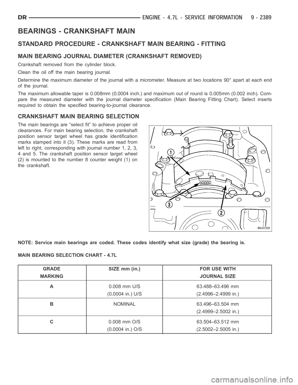
The main bearings are “select fit” to achieve proper oil
clearances. For main bearing selection, the crankshaft
position sensor target wheel has grade identification
marks stamped into it (3). These marks are read from
left to right, corresponding with journal number 1, 2, 3,
4 and 5. The crankshaft position sensor target wheel
(2) is mounted to the number 8 counter weight (1) on
the crankshaft.
NOTE: Service main bearings are coded. These codes identify what size (grade) the bearing is.
MAIN BEARING SELECTION CHART - 4.7L
GRADE SIZE mm (in.) FOR USE WITH
MARKING JOURNAL SIZE
A0.008 mm U/S 63.488–63.496 mm
(0.0004 in.) U/S (2.4996–2.4999 in.)
BNOMINAL 63.496–63.504 mm
(2.4999–2.5002 in.)
C0.008 mm O/S 63.504–63.512 mm
(0.0004 in.) O/S (2.5002–2.5005 in.)
Page 1706 of 5267
REMOVAL
1. Disconnect negative cable from battery.
2. Remove the following components:
Oil pan and gasket/windage tray (Refer to 9 - ENGINE/LUBRICATION/OIL PAN -REMOVAL).
Cylinder head covers (Refer to 9 - ENGINE/CYLINDER HEAD/CYLINDER HEAD COVER(S) - REMOVAL) and
(Refer to 9 - ENGINE/CYLINDER HEAD/CYLINDER HEAD COVER(S) - REMOVAL).
Timing chain cover (Refer to 9 - ENGINE/VALVE TIMING/TIMING BELT / CHAIN COVER(S) - REMOVAL).
Cylinder head(s) (Refer to 9 - ENGINE/CYLINDER HEAD - REMOVAL) and (Refer to 9 - ENGINE/CYLINDER
HEAD - REMOVAL).
3. If necessary, remove top ridge of cylinder bores with a reliable ridge reamer before removing pistons from cyl-
inder block.Be sure to keep tops of pistons covered during this operation.Pistons and connecting rods
must be removed from top of cylinder block. When removing piston and connecting rod assemblies from the
engine, rotate crankshaft so the each connecting rod is centered in cylinder bore.
CAUTION: DO NOT use a number stamp or a punch to mark connecting rods or caps,as damage to con-
necting rods could occur
NOTE: Connecting rods and bearing caps are not interchangeable and shouldbe marked before removing
to ensure correct reassembly.
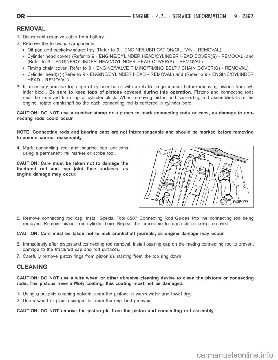
4. Mark connecting rod and bearing cap positions
using a permanent ink marker or scribe tool.
CAUTION: Care must be taken not to damage the
fractured rod and cap joint face surfaces, as
engine damage may occur.
5. Remove connecting rod cap. Install Special Tool 8507 Connecting Rod Guides into the connecting rod being
removed. Remove piston from cylinder bore. Repeat this procedure for eachpiston being removed.
CAUTION: Care must be taken not to nick crankshaft journals, as engine damage may occur
6. Immediately after piston and connecting rod removal, install bearing cap on the mating connecting rod to prevent
damage to the fractured cap and rod surfaces.
7. Carefully remove piston rings from piston(s), starting from the top ring down.
CLEANING
CAUTION: DO NOT use a wire wheel or other abrasive cleaning devise to clean the pistons or connecting
rods. The pistons have a Moly coating, this coating must not be damaged.
1. Using a suitable cleaning solvent clean the pistons in warm water and towel dry.
2. Use a wood or plastic scraper to clean the ring land grooves.
CAUTION: DO NOT remove the piston pin from the piston and connecting rod assembly.
Page 1739 of 5267
VALVE TIMING
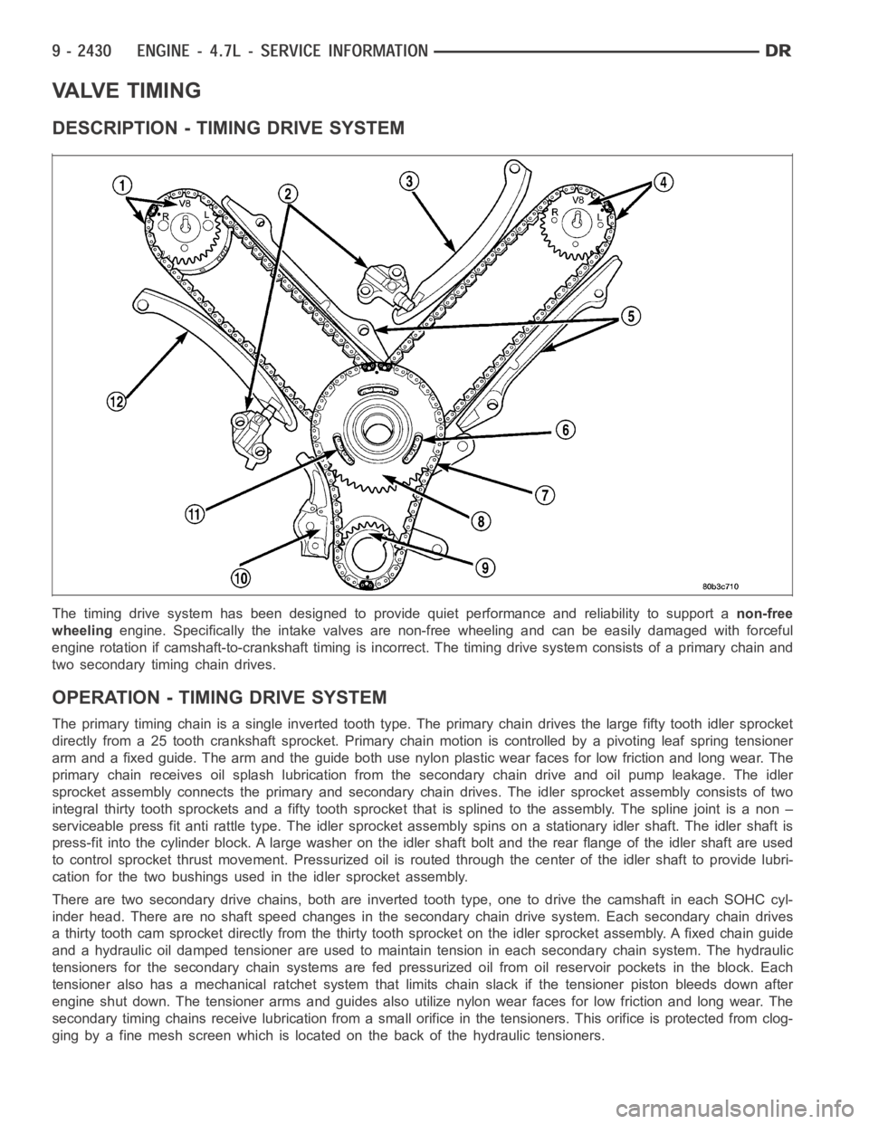
DESCRIPTION - TIMING DRIVE SYSTEM
The timing drive system has been designed to provide quiet performance andreliability to support anon-free
wheelingengine. Specifically the intake valves are non-free wheeling and can be easily damaged with forceful
engine rotation if camshaft-to-crankshaft timing is incorrect. The timing drive system consists of a primary chain and
two secondary timing chain drives.
OPERATION - TIMING DRIVE SYSTEM
The primary timing chain is a single inverted tooth type. The primary chaindrives the large fifty tooth idler sprocket
directly from a 25 tooth crankshaft sprocket. Primary chain motion is controlled by a pivoting leaf spring tensioner
arm and a fixed guide. The arm and the guide both use nylon plastic wear facesfor low friction and long wear. The
primary chain receives oil splash lubrication from the secondary chain drive and oil pump leakage. The idler
sprocket assembly connects the primary and secondary chain drives. The idler sprocket assembly consists of two
integral thirty tooth sprockets and afifty tooth sprocket that is splinedto the assembly. The spline joint is a non –
serviceable press fit anti rattle type. The idler sprocket assembly spinson a stationary idler shaft. The idler shaft is
press-fit into the cylinder block. A large washer on the idler shaft bolt and the rear flange of the idler shaft are used
to control sprocket thrust movement. Pressurized oil is routed through the center of the idler shaft to provide lubri-
cation for the two bushings used in the idler sprocket assembly.
There are two secondary drive chains, both are inverted tooth type, one to drive the camshaft in each SOHC cyl-
inder head. There are no shaft speed changes in the secondary chain drive system. Each secondary chain drives
a thirty tooth cam sprocket directly from the thirty tooth sprocket on the idler sprocket assembly. A fixed chain guide
and a hydraulic oil damped tensioner are used to maintain tension in each secondary chain system. The hydraulic
tensioners for the secondary chainsystems are fed pressurized oil from oil reservoir pockets in the block. Each
tensioner also has a mechanical ratchet system that limits chain slack if the tensioner piston bleeds down after
engine shut down. The tensioner arms and guides also utilize nylon wear faces for low friction and long wear. The
secondary timing chains receive lubrication from a small orifice in the tensioners. This orifice is protected from clog-
ging by a fine mesh screen which is located on the back of the hydraulic tensioners.
Page 1740 of 5267
STANDARD PROCEDURE
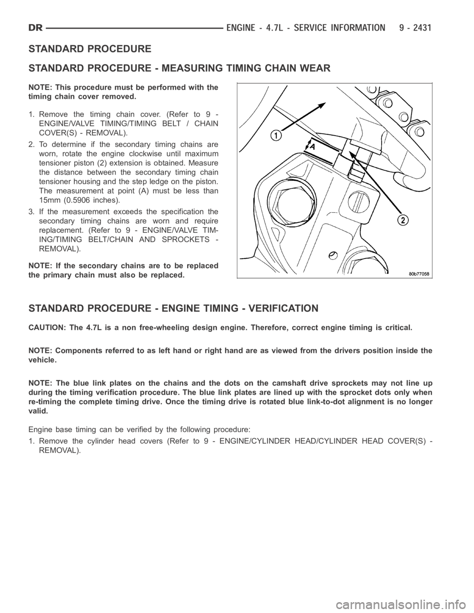
STANDARD PROCEDURE - MEASURING TIMING CHAIN WEAR
NOTE: This procedure must be performed with the
timing chain cover removed.
1.Removethetimingchaincover.(Referto9-
ENGINE/VALVE TIMING/TIMING BELT / CHAIN
COVER(S) - REMOVAL).
2. To determine if the secondary timing chains are
worn, rotate the engine clockwise until maximum
tensioner piston (2) extension is obtained. Measure
the distance between the secondary timing chain
tensioner housing and the step ledge on the piston.
The measurement at point (A) must be less than
15mm (0.5906 inches).
3. If the measurement exceeds the specification the
secondary timing chains are worn and require
replacement. (Refer to 9 - ENGINE/VALVE TIM-
ING/TIMING BELT/CHAIN AND SPROCKETS -
REMOVAL).
NOTE: If the secondary chains are to be replaced
the primary chain must also be replaced.
STANDARD PROCEDURE - ENGINE TIMING - VERIFICATION
CAUTION: The 4.7L is a non free-wheeling design engine. Therefore, correct engine timing is critical.
NOTE: Components referred to as left hand or right hand are as viewed from thedriverspositioninsidethe
vehicle.
NOTE: The blue link plates on the chains and the dots on the camshaft drive sprockets may not line up
during the timing verification procedure. The blue link plates are lined up with the sprocket dots only when
re-timing the complete timing drive.Once the timing drive is rotated bluelink-to-dot alignment is no longer
valid.
Engine base timing can be verified by the following procedure:
1. Remove the cylinder head covers (Refer to 9 - ENGINE/CYLINDER HEAD/CYLINDERHEADCOVER(S)-
REMOVAL).
Page 1746 of 5267
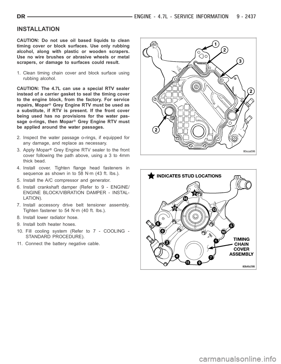
INSTALLATION
CAUTION: Do not use oil based liquids to clean
timing cover or block surfaces. Use only rubbing
alcohol, along with plastic or wooden scrapers.
Use no wire brushes or abrasive wheels or metal
scrapers, or damage to surfaces could result.
1. Clean timing chain cover and block surface using
rubbing alcohol.
CAUTION: The 4.7L can use a special RTV sealer
instead of a carrier gasket to seal the timing cover
to the engine block, from the factory. For service
repairs, Mopar
Grey Engine RTV must be used as
a substitute, if RTV is present. If the front cover
being used has no provisions for the water pas-
sage o-rings, then Mopar
Grey Engine RTV must
be applied around the water passages.
2. Inspect the water passage o-rings, if equipped for
any damage, and replace as necessary.
3. Apply Mopar
Grey Engine RTV sealer to the front
cover following the path above, using a 3 to 4mm
thick bead.
4. Install cover. Tighten flange head fasteners in
sequence as shown in to 58 Nꞏm (43 ft. lbs.).
5. Install the A/C compressor and generator.
6. Install crankshaft damper (Refer to 9 - ENGINE/
ENGINE BLOCK/VIBRATION DAMPER - INSTAL-
LATION).
7. Install accessory drive belt tensioner assembly.
Tighten fastener to 54 Nꞏm (40 ft. lbs.).
8. Install lower radiator hose.
9. Install both heater hoses.
10. Fill cooling system (Refer to 7 - COOLING -
STANDARD PROCEDURE).
11. Connect the battery negative cable.
Page 1749 of 5267
CAUTION: Care should be taken not to damage
camshaft target wheel. Do not hold target wheel
while loosening or tightening camshaft sprocket.
Do not place the target wheel near a magnetic
source of any kind. A damaged or magnetized tar-
get wheel could cause a vehicle no start condition.
CAUTION: Do not forcefully rotate the camshafts
or crankshaft independently of each other. Damag-
ing intake valve to piston contact will occur.
Ensure negative battery cable is disconnected to
guard against accidental starter engagement.
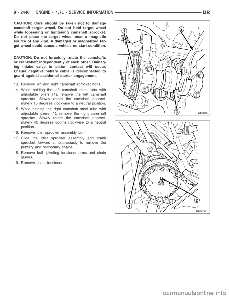
13. Remove left and right camshaft sprocket bolts.
14. While holding the left camshaft steel tube with
adjustable pliers (1), remove the left camshaft
sprocket. Slowly rotate the camshaft approxi-
mately 15 degrees clockwise to a neutral position.
15. While holding the right camshaft steel tube with
adjustable pliers (1), remove the right camshaft
sprocket. Slowly rotate the camshaft approxi-
mately 45 degrees counterclockwise to a neutral
position.
16. Remove idler sprocket assembly bolt.
17. Slide the idler sprocket assembly and crank
sprocket forward simultaneously to remove the
primary and secondary chains.
18. Remove both pivoting tensioner arms and chain
guides.
19. Remove chain tensioner.
Page 1760 of 5267
DIAGNOSIS AND TESTING - ENGINE DIAGNOSIS - MECHANICAL
CONDITION POSSIBLE CAUSES CORRECTIONS
NOISY VALVES 1. High or low oil level in
crankcase.1. (Refer to LUBRICATION &
MAINTENANCE -
SPECIFICATIONS)
2. Thin or diluted oil. 2. Change oil and filter.
3. Low oil pressure. 3. Check oil pump, if Ok, check rod
and main bearings for excessive
wear.
4. Dirt in lash adjusters. 4. Replace as necessary.
5. Worn rocker arms. 5. Replace as necessary.
6. Worn lash adjusters 6. Replace as necessary.
7. Worn valve guides. 7. (Refer to 9 - ENGINE/CYLINDER
HEAD/INTAKE/EXHAUST VALVES
& SEATS - STANDARD
PROCEDURE)
8. Excessive runout of valve seats
on valve faces.8. (Refer to 9 - ENGINE/CYLINDER
HEAD/INTAKE/EXHAUST VALVES
& SEATS - STANDARD
PROCEDURE)
CONNECTING ROD NOISE 1. Insufficient oil supply. 1. (Refer to LUBRICATION&
MAINTENANCE -
SPECIFICATIONS)
2. Low oil pressure. 2. Check oil pump, if Ok, check rod
and main bearings for excessive
wear.
3. Thin or diluted oil. 3. Change oil and filter.
4. Excessive bearing clearance. 4. Replace as necessary.
5. Connecting rod journal
out-of-round.5. Service or replace crankshaft.
6. Misaligned connecting rods. 6. Replace bent connecting rods.
MAIN BEARING NOISE 1. Insufficient oil supply. 1. (Refer to LUBRICATION &
MAINTENANCE -
SPECIFICATIONS)
2. Low oil pressure. 2. Check oil pump, if Ok, check rod
and main bearings for excessive
wear.
3. Thin or diluted oil. 3. Change oil and filter.
4. Excessive bearing clearance. 4. Replace as necessary.
5. Excessive end play. 5. Check thrust washers for wear.
6. Crankshaft journal out-of round. 6. Service or replace crankshaft.
7. Loose flywheel or torque
converter.7. Tighten to correct torque
DIAGNOSIS AND TESTING - CYLINDER COMPRESSION PRESSURE
The results of a cylinder compressionpressure test can be utilized to diagnose several engine malfunctions.