2006 DODGE RAM SRT-10 wheel
[x] Cancel search: wheelPage 1410 of 5267
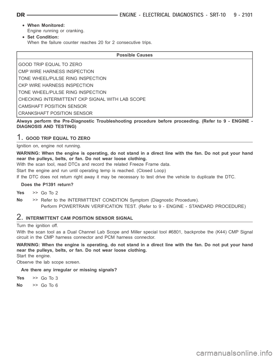
When Monitored:
Engine running or cranking.
Set Condition:
When the failure counter reaches 20 for 2 consecutive trips.
Possible Causes
GOOD TRIP EQUAL TO ZERO
CMP WIRE HARNESS INSPECTION
TONE WHEEL/PULSE RING INSPECTION
CKP WIRE HARNESS INSPECTION
TONE WHEEL/PULSE RING INSPECTION
CHECKING INTERMITTENT CKP SIGNAL WITH LAB SCOPE
CAMSHAFT POSITION SENSOR
CRANKSHAFT POSITION SENSOR
Always perform the Pre-Diagnostic Troubleshooting procedure before proceeding. (Refer to 9 - ENGINE -
DIAGNOSIS AND TESTING)
1.GOOD TRIP EQUAL TO ZERO
Ignition on, engine not running.
WARNING: When the engine is operating, do not stand in a direct line with thefan. Do not put your hand
near the pulleys, belts, or fan. Do not wear loose clothing.
With the scan tool, read DTCs and record the related Freeze Frame data.
Start the engine and run until operating temp is reached. (Closed Loop)
If the DTC does not return right away it may be necessary to test drive the vehicle to duplicate the DTC.
Does the P1391 return?
Ye s>>
Go To 2
No>>
Refer to the INTERMITTENT CONDITIONSymptom (Diagnostic Procedure).
Perform POWERTRAIN VERIFICATION TEST. (Refer to 9 - ENGINE - STANDARD PROCEDURE)
2.INTERMITTENT CAM POSITION SENSOR SIGNAL
Turn the ignition off.
With the scan tool as a Dual Channel Lab Scope and Miller special tool #6801,backprobe the (K44) CMP Signal
circuit in the CMP harness connector and PCM harness connector.
WARNING: When the engine is operating, do not stand in a direct line with thefan. Do not put your hand
near the pulleys, belts, or fan. Do not wear loose clothing.
Start the engine.
Observe the lab scope screen.
Are there any irregular or missing signals?
Ye s>>
Go To 3
No>>
Go To 6
Page 1411 of 5267
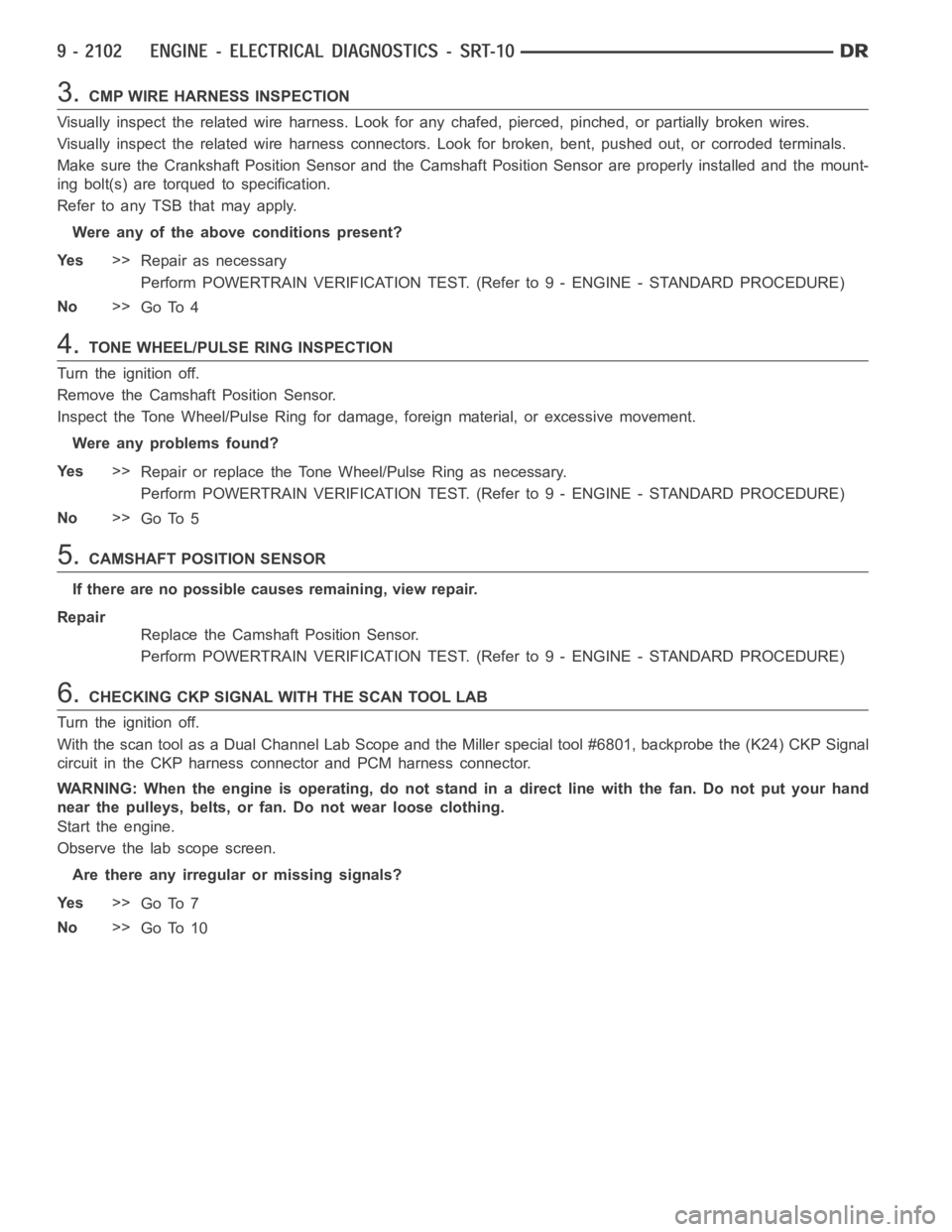
3.CMP WIRE HARNESS INSPECTION
Visually inspect the related wire harness. Look for any chafed, pierced, pinched, or partially broken wires.
Visually inspect the related wire harness connectors. Look for broken, bent, pushed out, or corroded terminals.
Make sure the Crankshaft Position Sensor and the Camshaft Position Sensorare properly installed and the mount-
ing bolt(s) are torqued to specification.
Refer to any TSB that may apply.
Were any of the above conditions present?
Ye s>>
Repair as necessary
Perform POWERTRAIN VERIFICATION TEST. (Refer to 9 - ENGINE - STANDARD PROCEDURE)
No>>
Go To 4
4.TONE WHEEL/PULSE RING INSPECTION
Turn the ignition off.
Remove the Camshaft Position Sensor.
Inspect the Tone Wheel/Pulse Ring for damage, foreign material, or excessive movement.
Were any problems found?
Ye s>>
Repair or replace the Tone Wheel/Pulse Ring as necessary.
Perform POWERTRAIN VERIFICATION TEST. (Refer to 9 - ENGINE - STANDARD PROCEDURE)
No>>
Go To 5
5.CAMSHAFT POSITION SENSOR
If there are no possible causes remaining, view repair.
Repair
Replace the Camshaft Position Sensor.
Perform POWERTRAIN VERIFICATION TEST. (Refer to 9 - ENGINE - STANDARD PROCEDURE)
6.CHECKING CKP SIGNAL WITH THE SCAN TOOL LAB
Turn the ignition off.
With the scan tool as a Dual Channel Lab Scope and the Miller special tool #6801, backprobe the (K24) CKP Signal
circuit in the CKP harness connector and PCM harness connector.
WARNING: When the engine is operating, do not stand in a direct line with thefan. Do not put your hand
near the pulleys, belts, or fan. Do not wear loose clothing.
Start the engine.
Observe the lab scope screen.
Are there any irregular or missing signals?
Ye s>>
Go To 7
No>>
Go To 10
Page 1412 of 5267
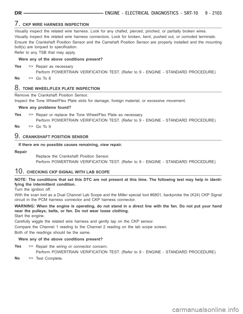
7.CKP WIRE HARNESS INSPECTION
Visually inspect the related wire harness. Look for any chafed, pierced, pinched, or partially broken wires.
Visually inspect the related wire harness connectors. Look for broken, bent, pushed out, or corroded terminals.
Ensure the Crankshaft Position Sensor and the Camshaft Position Sensor are properly installed and the mounting
bolt(s) are torqued to specification.
Refer to any TSB that may apply.
Were any of the above conditions present?
Ye s>>
Repair as necessary
Perform POWERTRAIN VERIFICATION TEST. (Refer to 9 - ENGINE - STANDARD PROCEDURE)
No>>
Go To 8
8.TONE WHEEL/FLEX PLATE INSPECTION
Remove the Crankshaft Position Sensor.
Inspect the Tone Wheel/Flex Plate slots for damage, foreign material, or excessive movement.
Were any problems found?
Ye s>>
Repair or replace the Tone Wheel/Flex Plate as necessary.
Perform POWERTRAIN VERIFICATION TEST. (Refer to 9 - ENGINE - STANDARD PROCEDURE)
No>>
Go To 9
9.CRANKSHAFT POSITION SENSOR
If there are no possible causes remaining, view repair.
Repair
Replace the Crankshaft Position Sensor.
Perform POWERTRAIN VERIFICATION TEST. (Refer to 9 - ENGINE - STANDARD PROCEDURE)
10.CHECKING CKP SIGNAL WITH LAB SCOPE
NOTE: The conditions that set this DTC are not present at this time. The following test may help in identi-
fying the intermittent condition.
Turn the ignition off.
With the scan tool as a Dual Channel Lab Scope and the Miller special tool #6801, backprobe the (K24) CKP Signal
circuit in the PCM harness connector and CKP harness connector.
WARNING: When the engine is operating, do not stand in a direct line with thefan. Do not put your hand
near the pulleys, belts, or fan. Do not wear loose clothing.
Start the engine.
Carefully wiggle the related wire harness and gently tap on the CKP sensor.
Compare the Channel 1 reading to the Channel 2 reading on the lab scope screen.
Both of the readings should be the same.
Were any of the above conditions present?
Ye s>>
Repair the wiring or connector concern.
Perform POWERTRAIN VERIFICATION TEST. (Refer to 9 - ENGINE - STANDARD PROCEDURE)
No>>
Te s t C o m p l e t e .
Page 1413 of 5267
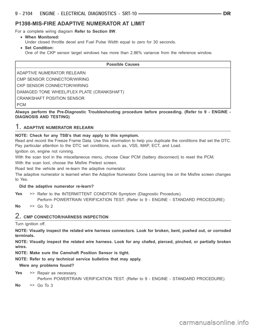
P1398-MIS-FIRE ADAPTIVE NUMERATOR AT LIMIT
For a complete wiring diagramRefer to Section 8W.
When Monitored:
Under closed throttle decel and Fuel Pulse Width equal to zero for 30 seconds.
Set Condition:
One of the CKP sensor target windows has more than 2.86% variance from the reference window.
Possible Causes
ADAPTIVE NUMERATOR RELEARN
CMP SENSOR CONNECTOR/WIRING
CKP SENSOR CONNECTOR/WIRING
DAMAGED TONE WHEEL/FLEX PLATE (CRANKSHAFT)
CRANKSHAFT POSITION SENSOR
PCM
Always perform the Pre-Diagnostic Troubleshooting procedure before proceeding. (Refer to 9 - ENGINE -
DIAGNOSIS AND TESTING)
1.ADAPTIVE NUMERATOR RELEARN
NOTE: Check for any TSB’s that may apply to this symptom.
Read and record the Freeze Frame Data. Use this information to help you duplicate the conditions that set the DTC.
Pay particular attention to the DTC set conditions, such as, VSS, MAP, ECT,and Load.
Ignition on, engine not running.
With the scan tool in the miscellaneous menu, choose Clear PCM (battery disconnect) to reset the PCM.
With the scan tool, choose the Misfire Pretest screen.
Road test the vehicle and re-learn the adaptive numerator.
The adaptive numerator is learned when the Adaptive Numerator Done Learning line on the Misfire screen changes
to Yes.
Did the adaptive numerator re-learn?
Ye s>>
Refer to the INTERMITTENT CONDITIONSymptom (Diagnostic Procedure).
Perform POWERTRAIN VERIFICATION TEST. (Refer to 9 - ENGINE - STANDARD PROCEDURE)
No>>
Go To 2
2.CMP CONNECTOR/HARNESS INSPECTION
Turn ignition off.
NOTE: Visually inspect the related wire harness connectors. Look for broken, bent, pushed out, or corroded
terminals.
NOTE: Visually inspect the related wire harness. Look for any chafed, pierced, pinched, or partially broken
wires.
NOTE: Make sure the Camshaft Position Sensor is tight.
NOTE: Refer to any technical service bulletins that may apply.
Were any problems found?
Ye s>>
Repair as necessary.
Perform POWERTRAIN VERIFICATION TEST. (Refer to 9 - ENGINE - STANDARD PROCEDURE)
No>>
Go To 3
Page 1414 of 5267
3.CKP CONNECTOR/HARNESS INSPECTION
NOTE: Visually inspect the Crankshaft Position Sensor and related wire harness connectors. Look for bro-
ken, bent, pushed out, or corroded terminals.
NOTE: Visually inspect the related wire harness. Look for any chafed, pierced, pinched, or partially broken
wires.
NOTE:VerifytheCrankPositionSensorisproperlyinstalled.
Were any problems found?
Ye s>>
Repair as necessary.
Perform POWERTRAIN VERIFICATION TEST. (Refer to 9 - ENGINE - STANDARD PROCEDURE)
No>>
Go To 4
4.TONE WHEEL/FLEX PLATE INSPECTION
Disconnect and remove the Crankshaft Position Sensor.
Inspect the tone wheel/flexplate slots for damage, foreign material, or excessive movement.
Is the tone wheel/flexplate free from defects?
Ye s>>
Go To 5
No>>
Repair/replace tone wheel/flex plate as necessary.
Perform POWERTRAIN VERIFICATION TEST. (Refer to 9 - ENGINE - STANDARD PROCEDURE)
5.CRANKSHAFT POSITION SENSOR l
With the scan tool lab scope probe and the Miller special tool #6801, back probe the (K24) CKP Signal circuit in the
PCM harness connector.
WARNING: WARNING: WHEN THE ENGINE IS OPERATING, DO NOT STAND IN A DIRECT LINEWITHTHE
FAN. DO NOT PUT YOUR HANDS NEAR THE PULLEYS, BELTS OR FAN. DO NOT WEAR LOOSE CLOTHING..
Start the engine and observe the lab scope screen for any erratic CKP Sensorpulses.
NOTE: Turn the ignition off before continuing.
Were any erratic Crank Position signals detected.
Ye s .>>
Replace the Crankshaft Position Sensor.
Perform POWERTRAIN VERIFICATION TEST. (Refer to 9 - ENGINE - STANDARD PROCEDURE)
No.>>
Go To 6
6.PCM
NOTE: Before continuing, check the PCM harness connector terminals for corrosion, damage, or terminal
push out. Repair as necessary.
Using the schematics as a guide, inspect the wire harness and connectors. Pay particular attention to all Power and
Ground circuits.
If there are no possible causes remaining, view repair.
Repair
Replace and program the Powertrain Control Module per Service Information.
Perform POWERTRAIN VERIFICATION TEST. (Refer to 9 - ENGINE - STANDARD PROCEDURE)
Page 1492 of 5267
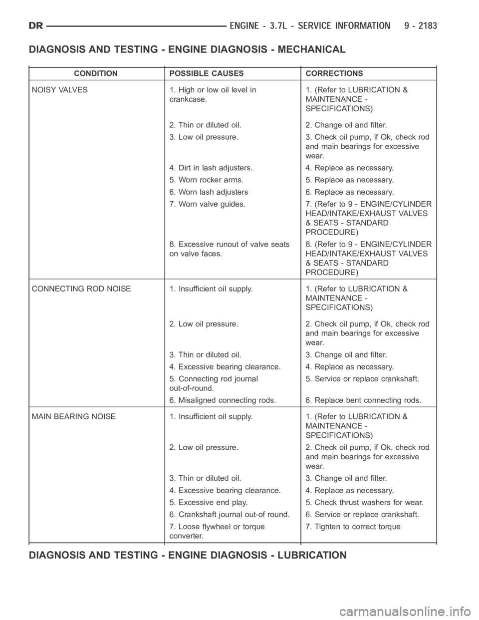
DIAGNOSIS AND TESTING - ENGINE DIAGNOSIS - MECHANICAL
CONDITION POSSIBLE CAUSES CORRECTIONS
NOISY VALVES 1. High or low oil level in
crankcase.1. (Refer to LUBRICATION &
MAINTENANCE -
SPECIFICATIONS)
2. Thin or diluted oil. 2. Change oil and filter.
3. Low oil pressure. 3. Check oil pump, if Ok, check rod
and main bearings for excessive
wear.
4. Dirt in lash adjusters. 4. Replace as necessary.
5. Worn rocker arms. 5. Replace as necessary.
6. Worn lash adjusters 6. Replace as necessary.
7. Worn valve guides. 7. (Refer to 9 - ENGINE/CYLINDER
HEAD/INTAKE/EXHAUST VALVES
& SEATS - STANDARD
PROCEDURE)
8. Excessive runout of valve seats
on valve faces.8. (Refer to 9 - ENGINE/CYLINDER
HEAD/INTAKE/EXHAUST VALVES
& SEATS - STANDARD
PROCEDURE)
CONNECTING ROD NOISE 1. Insufficient oil supply. 1. (Refer to LUBRICATION&
MAINTENANCE -
SPECIFICATIONS)
2. Low oil pressure. 2. Check oil pump, if Ok, check rod
and main bearings for excessive
wear.
3. Thin or diluted oil. 3. Change oil and filter.
4. Excessive bearing clearance. 4. Replace as necessary.
5. Connecting rod journal
out-of-round.5. Service or replace crankshaft.
6. Misaligned connecting rods. 6. Replace bent connecting rods.
MAIN BEARING NOISE 1. Insufficient oil supply. 1. (Refer to LUBRICATION &
MAINTENANCE -
SPECIFICATIONS)
2. Low oil pressure. 2. Check oil pump, if Ok, check rod
and main bearings for excessive
wear.
3. Thin or diluted oil. 3. Change oil and filter.
4. Excessive bearing clearance. 4. Replace as necessary.
5. Excessive end play. 5. Check thrust washers for wear.
6. Crankshaft journal out-of round. 6. Service or replace crankshaft.
7. Loose flywheel or torque
converter.7. Tighten to correct torque
DIAGNOSIS AND TESTING - ENGINE DIAGNOSIS - LUBRICATION
Page 1523 of 5267
CAMSHAFT
DESCRIPTION
The camshafts consist of powdered metal steel lobes which are sinter-bonded to a steel tube. Four bearing journals
are machined into the camshaft. Camshaft end play is controlled by two thrust walls that border the nose piece
journal.
REMOVAL
CAUTION: When the timing chain is removed and the cylinder heads are still installed, DO NOT forcefully
rotate the camshafts or crankshaft independently of each other. Severe valve and/or piston damage can
occur.
CAUTION: When removing the cam sprocket, timing chains or camshaft, Failure to use Special Tool 8379
will result in hydraulic tensioner ratchet over extension, requiring timing chain cover removal to reset the
tensioner ratchet.
1. Remove cylinder head cover (Refer to 9 - ENGINE/CYLINDER HEAD/CYLINDERHEAD COVER(S) -
REMOVAL).
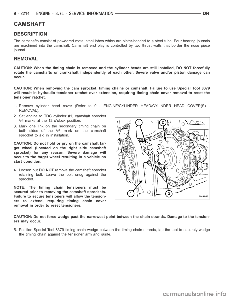
2. Set engine to TDC cylinder #1, camshaft sprocket
V6 marks at the 12 o’clock position.
3. Mark one link on the secondary timing chain on
both sides of the V6 mark on the camshaft
sprocket to aid in installation.
CAUTION: Do not hold or pry on the camshaft tar-
get wheel (Located on the right side camshaft
sprocket) for any reason, Severe damage will
occur to the target wheel resulting in a vehicle no
start condition.
4. Loosen butDO NOTremove the camshaft sprocket
retaining bolt. Leave the bolt snug against the
sprocket.
NOTE: The timing chain tensioners must be
secured prior to removing the camshaft sprockets.
Failure to secure tensioners will allow the tension-
erstoextend,requiringtimingchaincover
removal in order to reset tensioners.
CAUTION: Do not force wedge past the narrowest point between the chain strands. Damage to the tension-
ers may occur.
5. Position Special Tool 8379 timing chain wedge between the timing chain strands, tap the tool to securely wedge
the timing chain against the tensioner arm and guide.
Page 1538 of 5267
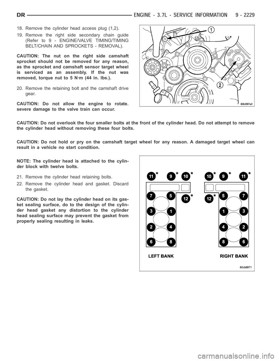
18. Remove the cylinder head access plug (1,2).
19. Remove the right side secondary chain guide
(Refer to 9 - ENGINE/VALVE TIMING/TIMING
BELT/CHAIN AND SPROCKETS - REMOVAL).
CAUTION: The nut on the right side camshaft
sprocket should not be removed for any reason,
as the sprocket and camshaft sensor target wheel
is serviced as an assembly. If the nut was
removed, torque nut to 5 Nꞏm (44 in. lbs.).
20. Remove the retaining bolt and the camshaft drive
gear.
CAUTION: Do not allow the engine to rotate.
severe damage to the valve train can occur.
CAUTION: Do not overlook the four smaller bolts at the front of the cylinderhead.Donotattempttoremove
the cylinder head without removing these four bolts.
CAUTION: Do not hold or pry on the camshaft target wheel for any reason. A damaged target wheel can
result in a vehicle no start condition.
NOTE: The cylinder head is attached to the cylin-
der block with twelve bolts.
21. Remove the cylinder head retaining bolts.
22. Remove the cylinder head and gasket. Discard
the gasket.
CAUTION: Do not lay the cylinder head on its gas-
ket sealing surface, do to the design of the cylin-
der head gasket any distortion to the cylinder
head sealing surface may prevent the gasket from
properly sealing resulting in leaks.