Page 1541 of 5267
CAUTION: The nut on the right side camshaft sprocket should not be removed for any reason, as the
sprocket and camshaft sensor target wheel is serviced as an assembly. If the nut was removed, torque nut
to 5 NM ( 60 in. lbs.).
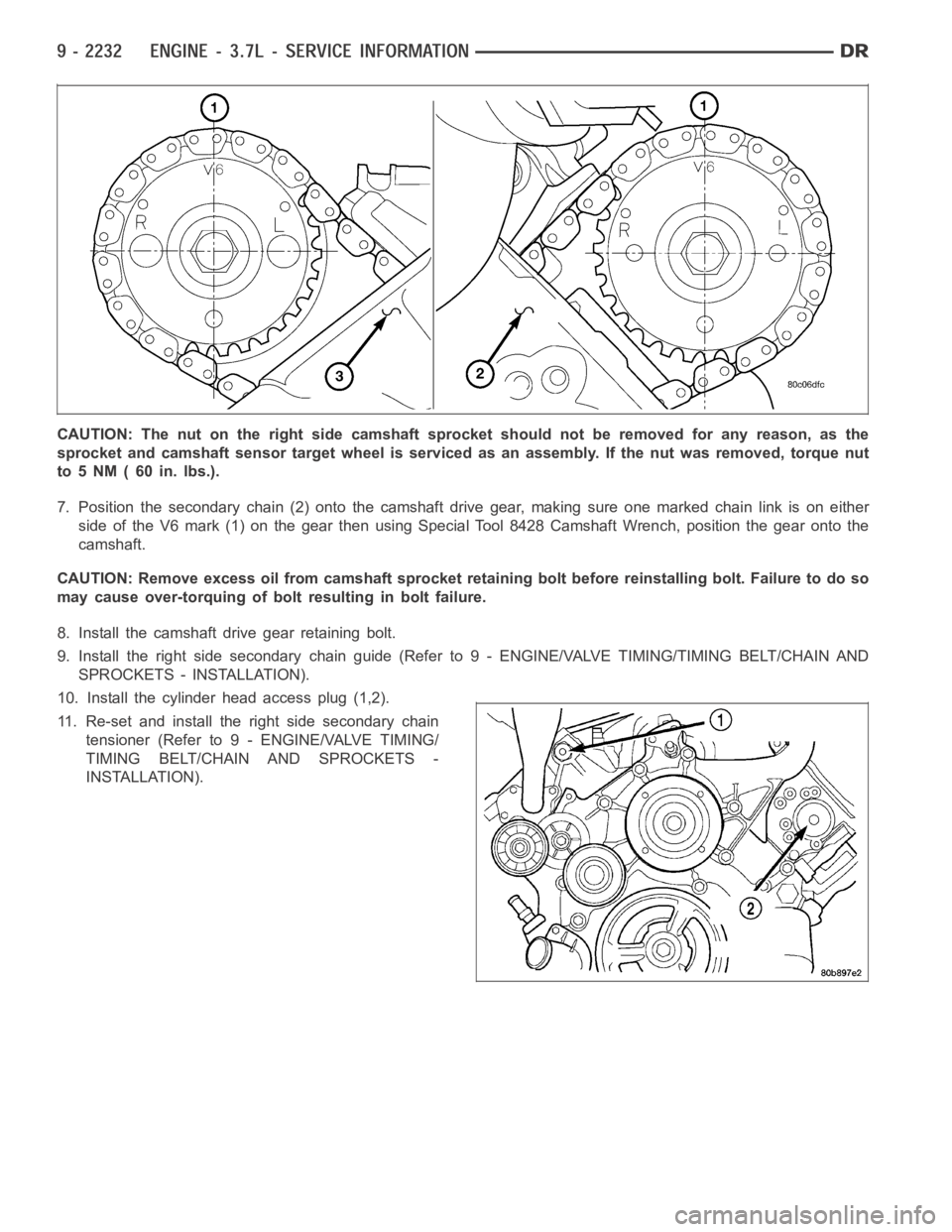
7. Position the secondary chain (2) onto the camshaft drive gear, making sure one marked chain link is on either
side of the V6 mark (1) on the gear then using Special Tool 8428 Camshaft Wrench, position the gear onto the
camshaft.
CAUTION: Remove excess oil from camshaft sprocket retaining bolt before reinstalling bolt. Failure to do so
may cause over-torquing of bolt resulting in bolt failure.
8. Install the camshaft drive gear retaining bolt.
9. Install the right side secondary chain guide (Refer to 9 - ENGINE/VALVE TIMING/TIMING BELT/CHAIN AND
SPROCKETS - INSTALLATION).
10. Install the cylinder head access plug (1,2).
11. Re-set and install the right side secondary chain
tensioner (Refer to 9 - ENGINE/VALVE TIMING/
TIMING BELT/CHAIN AND SPROCKETS -
INSTALLATION).
Page 1544 of 5267
CAUTION: Do not hold or pry on the camshaft tar-
get wheel for any reason, Severe damage will
occur to the target wheel. A damaged target wheel
could cause a vehicle no start condition.
4. Loosen butDO NOTremove the camshaft sprocket
retaining bolt. Leave bolt snug against sprocket.
NOTE: The timing chain tensioners must be
secured prior to removing the camshaft sprockets.
Failure to secure tensioners will allow the tension-
erstoextend,requiringtimingchaincover
removal in order to reset tensioners.
CAUTION: Do not force wedge past the narrowest
point between the chain strands. Damage to the
tensioners may occur.
5. Position Special Tool 8379 timing chain wedge (1)
between the timing chain strands. Tap the tool to
securely wedge the timing chain against the ten-
sioner arm and guide.
Page 1555 of 5267
CRANKSHAFT
DESCRIPTION
The crankshaft (1) is constructed of nodular cast iron.
The crankshaft is a three throw split pin design with
six counterweights for balancing purposes. The crank-
shaft is supported by four select fit main bearings with
the No. 2 serving as the thrust washer location. The
main journals of the crankshaft are cross drilled to
improve rod bearing lubrication. The No. 6 counter-
weight has provisions for crankshaft position sensor
target wheel (2) mounting. The select fit main bearing
markings are located on the rear side of the target
wheel. The crankshaft oil seals are one piece design.
The front oil seal is retained in the timing chain cover,
and the rear seal is pressed in to a bore formed by
the cylinder block and the bedplate assembly.
Page 1556 of 5267
REMOVAL
NOTE: To remove the crankshaft from the engine, the engine must be removed from the vehicle.
1. Remove the engine (Refer to 9 - ENGINE - REMOVAL).
2. Remove the engine oil pump (Refer to 9- ENGINE/LUBRICATION/OIL PUMP - REMOVAL).
CAUTION: DO NOT pry on the oil pan gasket when removing the oil pan, The oil pan gasket is mounted to
the cylinder block in three locations and will remain attached to block when removing oil pan. Gasket can
not be removed with oil pan.
3. Remove the bedplate mounting bolts. Note the location of the two stud bolts for installation.
4. Remove the connecting rods from the crankshaft.
CAUTION: The bedplate to cylinder block mating surface is a critical sealing surface. Do not pry on or dam-
age this surface in anyway.
NOTE: The bedplate contains the lower main bearing halves. Use care when handling bedplate as not to
drop or damage bearing halves. Installing main bearing halves in the wrongposition will cause severe dam-
age to the crankshaft.
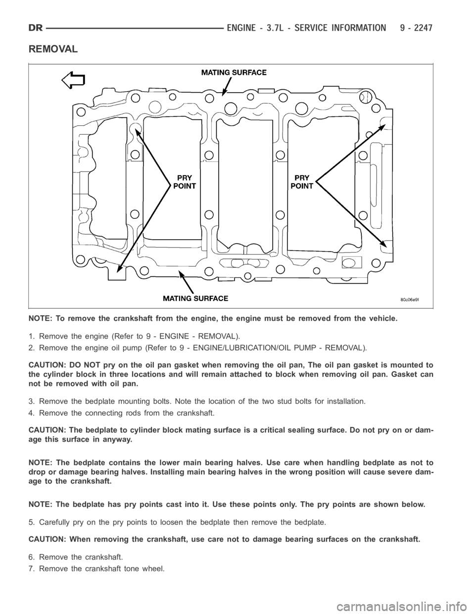
NOTE: The bedplate has pry points cast into it. Use these points only. The pry points are shown below.
5. Carefully pry on the pry points to loosen the bedplate then remove the bedplate.
CAUTION: When removing the crankshaft, use care not to damage bearing surfaces on the crankshaft.
6. Remove the crankshaft.
7. Remove the crankshaft tone wheel.
Page 1557 of 5267
INSPECTION
NOTE: Thoroughly inspect the connecting rod bearing bores and main bearing bores for scoring, blueing or
severe scratches. Further disassembly may be required.
If connecting rod bearing bores show damage, the cylinder heads must be removed to service the piston and rod
assemblies. If the bedplate or the cylinder block main bearing bores show damage the engine must be replaced.
1. If required, remove the main bearing halves from the cylinder block and bedplate.
2. Thoroughly clean the bedplate to cylinder block sealing surfaces and main bearing bores. Remove all oil and
sealant residue.
3. Inspect the bedplate main bearing bores for cracks, scoring or severe blueing. If either condition exists the
engine must be replaced.
4. Inspect the crankshaft thrust washers for scoring, scratches, wear or blueing. If either condition exist replace the
thrust washers.
5. Inspect the oil pan gasket/windage tray for splits, tears or cracks in the gasket sealing surfaces. Replace gasket
as necessary.
INSTALLATION
CAUTION: Main bearings are select fit. Refer to
Crankshaft Main Bearings in this section for
proper bearing selections.
CAUTION: When installing crankshaft, use care
not to damage bearing surfaces on the crankshaft.
NOTE: Apply sealant to the tone wheel retaining
screws prior to installation.
1. Lubricate upper main bearing halves with clean
engine oil.
2. Install the crankshaft tone wheel. Torque the
mountingscrewsto15Nꞏm(11ft.lbs.).
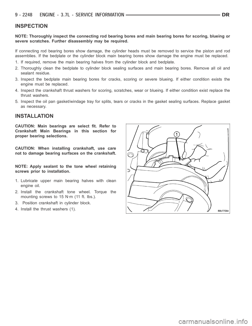
3. Position crankshaft in cylinder block.
4. Install the thrust washers (1).
Page 1560 of 5267
BEARINGS-CRANKSHAFT MAIN
STANDARD PROCEDURE
MAIN BEARING FITTING
SELECT FIT IDENTIFICATION
The main bearings are “select fit” to achieve proper oil
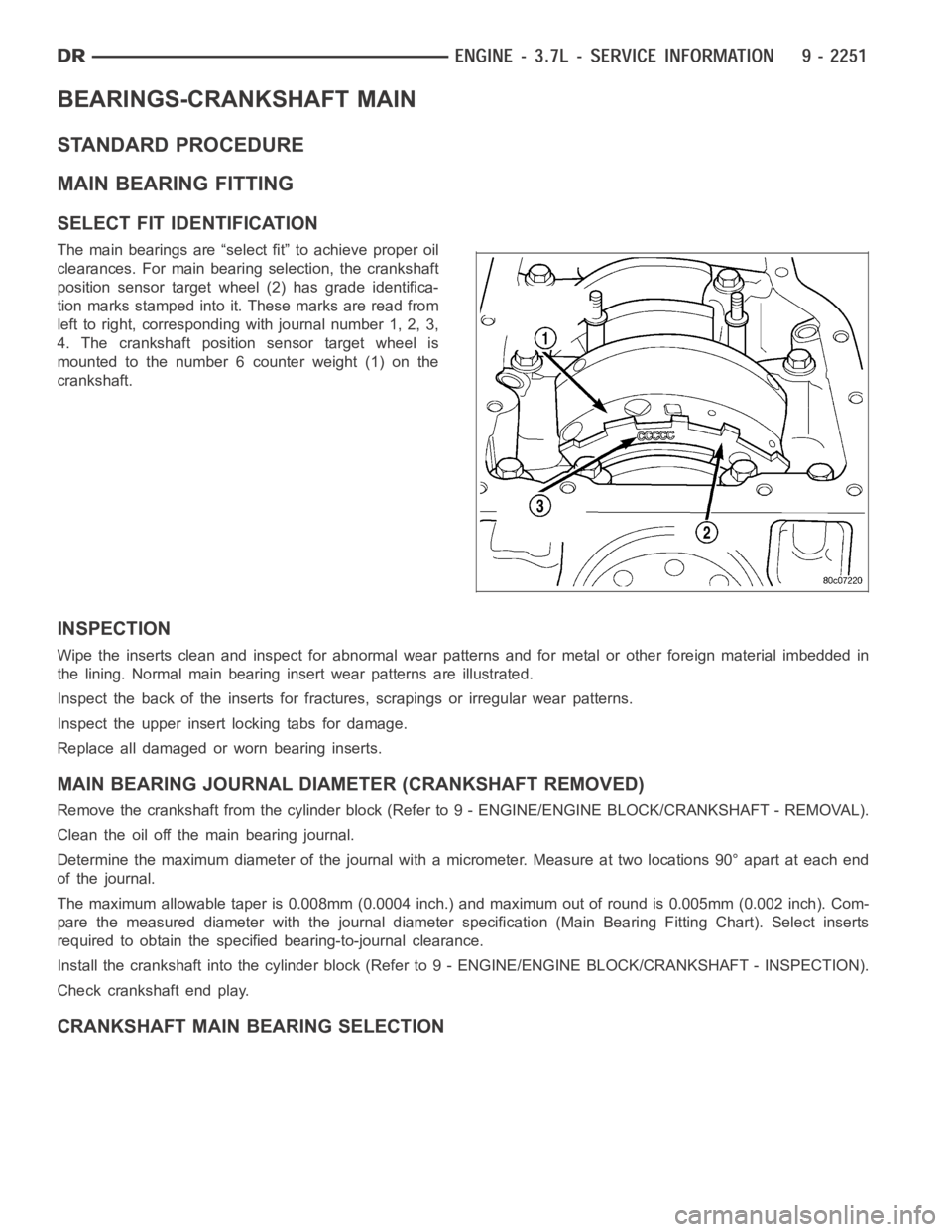
clearances. For main bearing selection, the crankshaft
position sensor target wheel (2) has grade identifica-
tion marks stamped into it. These marks are read from
left to right, corresponding with journal number 1, 2, 3,
4. The crankshaft position sensor target wheel is
mounted to the number 6 counter weight (1) on the
crankshaft.
INSPECTION
Wipe the inserts clean and inspect for abnormal wear patterns and for metalor other foreign material imbedded in
the lining. Normal main bearing insert wear patterns are illustrated.
Inspect the back of the inserts for fractures, scrapings or irregular wearpatterns.
Inspect the upper insert locking tabs for damage.
Replace all damaged or worn bearing inserts.
MAIN BEARING JOURNAL DIAMETER (CRANKSHAFT REMOVED)
Remove the crankshaft from the cylinder block (Refer to 9 - ENGINE/ENGINE BLOCK/CRANKSHAFT - REMOVAL).
Clean the oil off the main bearing journal.
Determine the maximum diameter of the journal with a micrometer. Measure at two locations 90° apart at each end
of the journal.
The maximum allowable taper is 0.008mm (0.0004 inch.) and maximum out of round is 0.005mm (0.002 inch). Com-
pare the measured diameter with the journal diameter specification (MainBearing Fitting Chart). Select inserts
required to obtain the specified bearing-to-journal clearance.
Install the crankshaft into the cylinder block (Refer to 9 - ENGINE/ENGINEBLOCK/CRANKSHAFT - INSPECTION).
Check crankshaft end play.
CRANKSHAFT MAIN BEARING SELECTION
Page 1571 of 5267
REMOVAL
1. Disconnect negative cable from battery.
2. Remove the following components:
Oil pan and gasket/windage tray (Refer to 9 - ENGINE/LUBRICATION/OIL PAN -REMOVAL).
Cylinder head covers (Refer to 9 - ENGINE/CYLINDER HEAD/CYLINDER HEAD COVER(S) - REMOVAL) and
(Refer to 9 - ENGINE/CYLINDER HEAD/CYLINDER HEAD COVER(S) - REMOVAL).
Timing chain cover (Refer to 9 - ENGINE/VALVE TIMING/TIMING BELT / CHAIN COVER(S) - REMOVAL).
Cylinder head(s) (Refer to 9 - ENGINE/CYLINDER HEAD - REMOVAL) and (Refer to 9 - ENGINE/CYLINDER
HEAD - REMOVAL).
3. If necessary, remove top ridge of cylinder bores with a reliable ridge reamer before removing pistons from cyl-
inder block.Be sure to keep tops of pistons covered during this operation.Pistons and connecting rods
must be removed from top of cylinder block. When removing piston and connecting rod assemblies from the
engine, rotate crankshaft so the each connecting rod is centered in cylinder bore.
CAUTION: DO NOT use a number stamp or a punch to mark connecting rods or caps,as damage to con-
necting rods could occur
NOTE: Connecting rods and bearing caps are not interchangeable and shouldbe marked before removing
to ensure correct reassembly.
4. Mark connecting rod and bearing cap positions using a permanent ink marker or scribe tool.
CAUTION: Care must be taken not to damage the fractured rod and cap joint face surfaces, as engine dam-
age may occur.
5. Remove connecting rod cap. Install Special Tool 8507 Connecting Rod Guides into the connecting rod being
removed. Remove piston from cylinder bore. Repeat this procedure for eachpiston being removed.
CAUTION: Care must be taken not to nick crankshaft journals, as engine damage may occur
6. Immediately after piston and connecting rod removal, install bearing cap on the mating connecting rod to prevent
damage to the fractured cap and rod surfaces.
CLEANING
CAUTION: DO NOT use a wire wheel or other abrasive cleaning devise to clean the pistons or connecting
rods. The pistons have a Moly coating, this coating must not be damaged.
1. Using a suitable cleaning solvent clean the pistons in warm water and towel dry.
2. Use a wood or plastic scraper to clean the ring land grooves.
CAUTION: DO NOT remove the piston pin from the piston and connecting rod assembly.
INSPECTION
Check the connecting rod journal for excessive wear, taper and scoring (Refer to 9 - ENGINE/ENGINE BLOCK/
CONNECTING ROD BEARINGS - STANDARD PROCEDURE).
Check the connecting rod for signs of twist or bending.
Check the piston for taper and elliptical shape before it is fitted into thecylinder bore (Refer to 9 - ENGINE/ENGINE
BLOCK/PISTON & CONNECTING ROD - STANDARD PROCEDURE).
Check the piston for scoring, or scraping marks in the piston skirts. Checkthe ring lands for cracks and/or deteri-
oration.
Page 1591 of 5267
CLEANING
1. Clean oil pan in solvent and wipe dry with a clean cloth.
2. Clean the oil pan gasket surface.DO NOTuse a grinder wheel or other abrasive tool to clean sealing surface.
3. Clean oil screen and tube thoroughly in clean solvent.
INSPECTION
1. Inspect oil drain plug and plug hole for stripped or damaged threads. Repair as necessary.
2. Inspect the oil pan mounting flange for bends or distortion. Straightenflange, if necessary.
INSTALLATION
1. Clean the oil pan gasket mating surface of the bed-
plate and oil pan.
2. Inspect integrated oil pan gasket (2), and replace
as necessary.
3. Position the integrated oil pan gasket/windage tray
assembly (2).
4. Install the oil pickup tube.
5. Install the mounting bolt and nuts. Tighten nuts to
28 Nꞏm (20 ft. lbs.).