2006 DODGE RAM SRT-10 wheel
[x] Cancel search: wheelPage 1764 of 5267
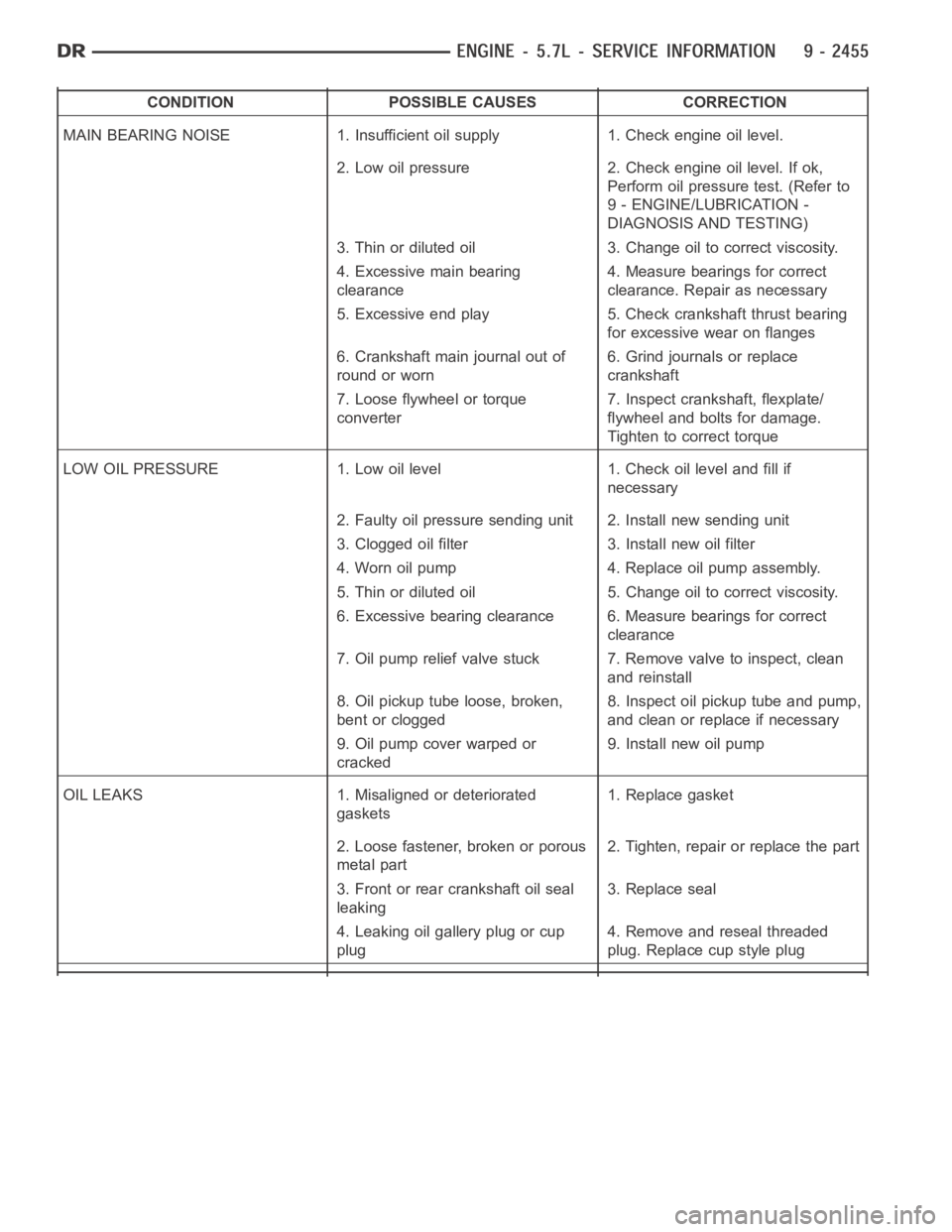
CONDITION POSSIBLE CAUSES CORRECTION
MAIN BEARING NOISE 1. Insufficient oil supply 1. Check engine oil level.
2. Low oil pressure 2. Check engine oil level. If ok,
Perform oil pressure test. (Refer to
9 - ENGINE/LUBRICATION -
DIAGNOSIS AND TESTING)
3. Thin or diluted oil 3. Change oil to correct viscosity.
4. Excessive main bearing
clearance4. Measure bearings for correct
clearance. Repair as necessary
5. Excessive end play 5. Check crankshaft thrust bearing
for excessive wear on flanges
6. Crankshaft main journal out of
round or worn6. Grind journals or replace
crankshaft
7. Loose flywheel or torque
converter7. Inspect crankshaft, flexplate/
flywheel and bolts for damage.
Tighten to correct torque
LOW OIL PRESSURE 1. Low oil level 1. Check oil level and fill if
necessary
2. Faulty oil pressure sending unit 2. Install new sending unit
3. Clogged oil filter 3. Install new oil filter
4. Worn oil pump 4. Replace oil pump assembly.
5. Thin or diluted oil 5. Change oil to correct viscosity.
6. Excessive bearing clearance 6. Measure bearings for correct
clearance
7. Oil pump relief valve stuck 7. Remove valve to inspect, clean
and reinstall
8. Oil pickup tube loose, broken,
bent or clogged8. Inspect oil pickup tube and pump,
and clean or replace if necessary
9. Oil pump cover warped or
cracked9. Install new oil pump
OIL LEAKS 1. Misaligned or deteriorated
gaskets1. Replace gasket
2. Loose fastener, broken or porous
metal part2. Tighten, repair or replace the part
3. Front or rear crankshaft oil seal
leaking3. Replace seal
4. Leaking oil gallery plug or cup
plug4. Remove and reseal threaded
plug. Replace cup style plug
Page 1781 of 5267
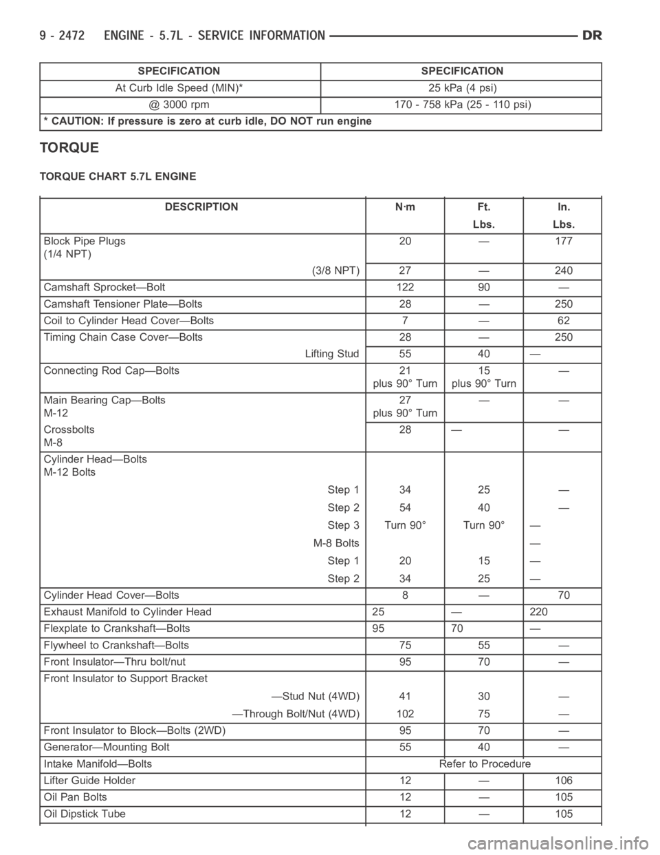
SPECIFICATION SPECIFICATION
At Curb Idle Speed (MIN)* 25 kPa (4 psi)
@ 3000 rpm 170 - 758 kPa (25 - 110 psi)
* CAUTION: If pressure is zero at curb idle, DO NOT run engine
TORQUE
TORQUE CHART 5.7L ENGINE
DESCRIPTION Nꞏm Ft. In.
Lbs. Lbs.
Block Pipe Plugs
(1/4 NPT)20 — 177
(3/8 NPT) 27 — 240
Camshaft Sprocket—Bolt 122 90 —
Camshaft Tensioner Plate—Bolts 28 — 250
Coil to Cylinder Head Cover—Bolts 7 — 62
Timing Chain Case Cover—Bolts 28 — 250
Lifting Stud 55 40 —
Connecting Rod Cap—Bolts 21
plus 90° Turn15
plus 90° Turn—
Main Bearing Cap—Bolts
M-1227
plus 90° Turn——
Crossbolts
M-828 — —
Cylinder Head—Bolts
M-12 Bolts
Step 1 34 25 —
Step 2 54 40 —
Step 3 Turn 90° Turn 90° —
M-8 Bolts —
Step 1 20 15 —
Step 2 34 25 —
Cylinder Head Cover—Bolts 8 — 70
Exhaust Manifold to Cylinder Head 25 — 220
Flexplate to Crankshaft—Bolts 95 70 —
Flywheel to Crankshaft—Bolts 75 55 —
Front Insulator—Thru bolt/nut 95 70 —
Front Insulator to Support Bracket
—Stud Nut (4WD) 41 30 —
—Through Bolt/Nut (4WD) 102 75 —
Front Insulator to Block—Bolts (2WD) 95 70 —
Generator—Mounting Bolt 55 40 —
Intake Manifold—Bolts Refer to Procedure
Lifter Guide Holder 12 — 106
Oil Pan Bolts 12 — 105
Oil Dipstick Tube 12 — 105
Page 1851 of 5267
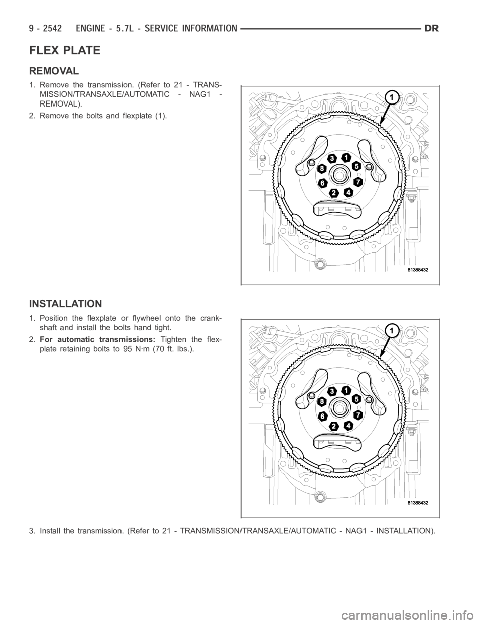
FLEX PLATE
REMOVAL
1. Remove the transmission. (Refer to 21 - TRANS-
MISSION/TRANSAXLE/AUTOMATIC - NAG1 -
REMOVAL).
2. Remove the bolts and flexplate (1).
INSTALLATION
1. Position the flexplate or flywheel onto the crank-
shaft and install the bolts hand tight.
2.For automatic transmissions:Tighten the flex-
plate retaining bolts to 95 Nꞏm (70 ft. lbs.).
3. Install the transmission. (Refer to 21 - TRANSMISSION/TRANSAXLE/AUTOMATIC - NAG1 - INSTALLATION).
Page 1857 of 5267
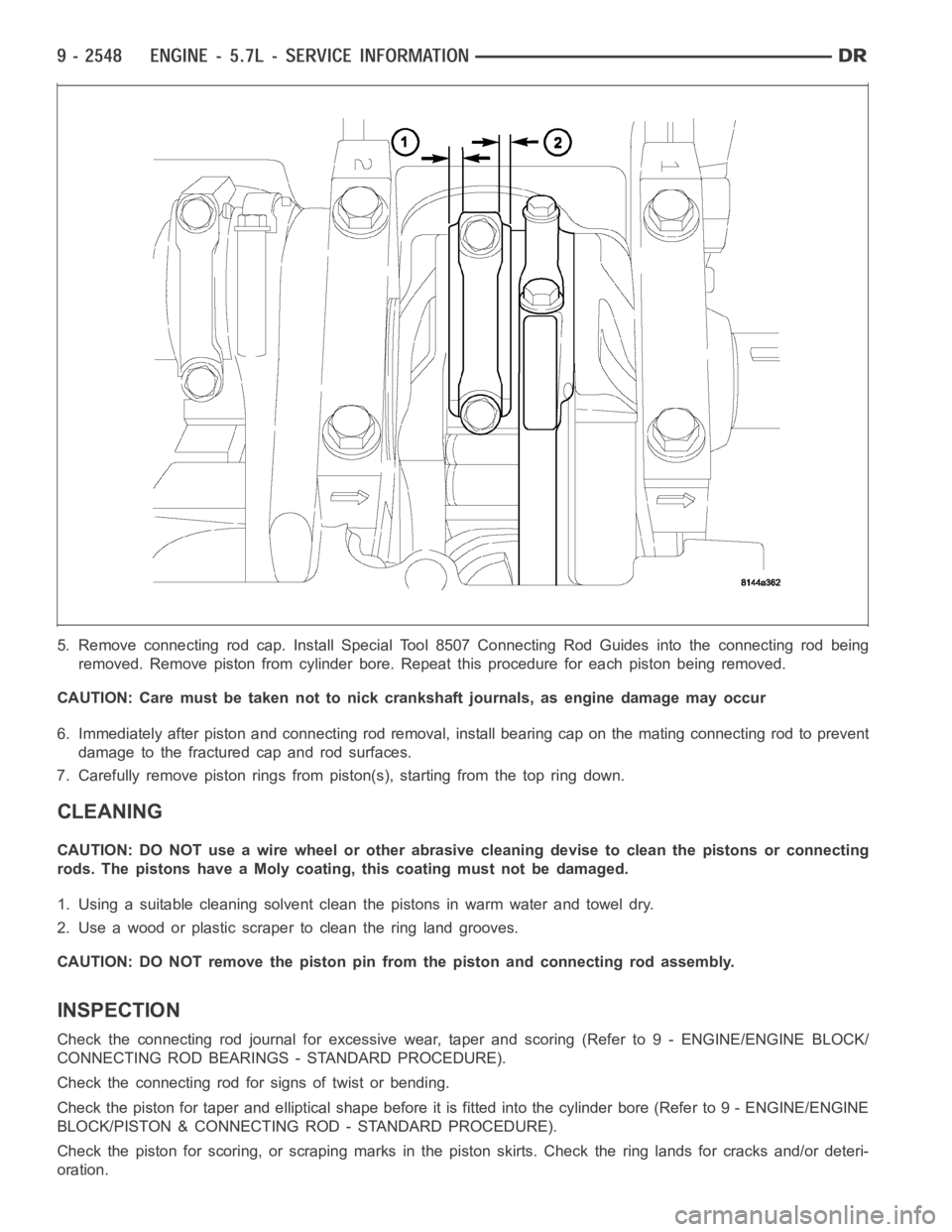
5. Remove connecting rod cap. Install Special Tool 8507 Connecting Rod Guides into the connecting rod being
removed. Remove piston from cylinder bore. Repeat this procedure for eachpiston being removed.
CAUTION: Care must be taken not to nick crankshaft journals, as engine damage may occur
6. Immediately after piston and connecting rod removal, install bearing cap on the mating connecting rod to prevent
damage to the fractured cap and rod surfaces.
7. Carefully remove piston rings from piston(s), starting from the top ring down.
CLEANING
CAUTION: DO NOT use a wire wheel or other abrasive cleaning devise to clean the pistons or connecting
rods. The pistons have a Moly coating, this coating must not be damaged.
1. Using a suitable cleaning solvent clean the pistons in warm water and towel dry.
2. Use a wood or plastic scraper to clean the ring land grooves.
CAUTION: DO NOT remove the piston pin from the piston and connecting rod assembly.
INSPECTION
Check the connecting rod journal for excessive wear, taper and scoring (Refer to 9 - ENGINE/ENGINE BLOCK/
CONNECTING ROD BEARINGS - STANDARD PROCEDURE).
Check the connecting rod for signs of twist or bending.
Check the piston for taper and elliptical shape before it is fitted into thecylinder bore (Refer to 9 - ENGINE/ENGINE
BLOCK/PISTON & CONNECTING ROD - STANDARD PROCEDURE).
Check the piston for scoring, or scraping marks in the piston skirts. Checkthe ring lands for cracks and/or deteri-
oration.
Page 1908 of 5267
CONDITION POSSIBLE CAUSES CORRECTION
3. Improperly operating vibration
damper3. Inspect/replace vibration damper.
4. Improperly operating electronically
controlled viscous fan drive.4. Inspect/replace fan drive.
5. Worn or damaged generator
bearing.5. Check/replace generator.
6. Flywheel housing misaligned. 6. Check/correct flywheel alignment.
7. Loose or broken power
component.7. Inspect the crankshaft and rods for
damage that causes an unbalance
condition. Repair/replace as required.
8. Worn or unbalanced driveline
components.8. Check/repair driveline components.
EXCESSIVE ENGINE
NOISES1. Drive belt squeal, insufficient
tension or abnormally high loading.1. Check the automatic tensioner and
inspect the drive belt. Make sure water
pump, tensioner pulley, fan hub, generator
and power steering pump turn freely.
2. Intake air or exhaust leaks. 2. Refer to Excessive Exhaust Smoke
(Refer to 9 - ENGINE - DIAGNOSIS AND
TESTING).
3. Excessive valve lash. 3. Adjust valves. Make sure the push rods
are not bent and rocker arms, adjusting
screws, crossheads, are not severely worn.
Replace bent or severely worn components.
4. Turbocharger noise. 4. Check turbocharger impeller and turbine
wheel for housing contact. Repair/replace
as required.
5. Gear train noise. 5. Visually inspect and measure gear
backlash. Replace gears as required.
6. Power function knock. 6. Check/replace rod and main bearings.
DIAGNOSIS AND TESTING -SMOKE DIAGNOSIS CHARTS
The following charts include possible causes and corrections forexcess or abnormalexhaust smoke. Small
amounts of exhaust smoke (at certain times) are to be considered normal fora diesel powered engine.
EXCESSIVE BLACK SMOKE
POSSIBLE CAUSE CORRECTION
Air filter dirty or plugged. Check Filter Minder
at air filter (Refer to 9 - ENGINE/
AIR INTAKE SYSTEM/AIR CLEANER ELEMENT -
REMOVAL).
Air intake system restricted. Check entire air intake system including all hoses and
tubes for restrictions, collapsed parts or damage.
Repair/replace as necessary.
Air Leak in Intake System. Check entire air intake system (Refer to 11 - EXHAUST
SYSTEM/TURBOCHARGER SYSTEM/CHARGE AIR
COOLER AND PLUMBING - DIAGNOSIS AND
TESTING) including all hoses and tubes for cracks,
loose clamps and/or holes in rubber ducts. Also check
intake manifold for loose mounting hardware.
Diagnostic Trouble Codes (DTC’s) active or multiple,
intermittent DTC’s.Refer to Powertrain Diagnostic Procedures Information.
Page 1909 of 5267
EXCESSIVE BLACK SMOKE
POSSIBLE CAUSE CORRECTION
Engine Control Module (ECM) not calibrated or ECM
has incorrect calibration.Refer to Powertrain Diagnostic Procedures Information.
Exhaust system restriction is above specifications. Check exhaust pipesfor damage/restrictions. Repair as
necessary.
Fuel grade is not correct or fuel quality is poor. Temporarily change fuel brands and note condition.
Change brand if necessary.
Fuel injection pump malfunctioning. A DTC may have been set. If so, refer toPowertrain
Diagnostic Procedures Information.
Fuel injector malfunctioning. A DTC may have been set. Perform “Cylinder
Performance Test
orCylinder Cutout Testusing DRB
scan tool to isolate individual cylinders. Also refer to
Powertrain Diagnostic Procedures Information and, to
(Refer to 14 - FUEL SYSTEM/FUEL INJECTION/FUEL
INJECTOR - DIAGNOSIS AND TESTING).
Fuel return system restricted. Check fuel return lines for restriction (Refer to 14 -
FUEL SYSTEM/FUEL DELIVERY - DIAGNOSIS AND
TESTING).
Intake manifold restricted. Remove restriction.
Manifold Air Pressure (Boost) Sensor or sensor circuit
malfunctioning.A DTC should have been set. Refer to Powertrain
Diagnostic Procedures Information.
Raw fuel in intake manifold. Fuel injectors leaking on engine shutdown. DoFuel
Injector Test (Refer to 14 - FUEL SYSTEM/FUEL
INJECTION/FUEL INJECTOR - DIAGNOSIS AND
TESTING).
Turbocharger air intake restriction. Remove restriction.
Turbocharger damaged. (Refer to 11 - EXHAUST SYSTEM/TURBOCHARGER
SYSTEM/TURBOCHARGER - INSPECTION).
Turbocharger has excess build up on compressor
wheel and/or diffuser vanes.(Refer to 11 - EXHAUST SYSTEM/TURBOCHARGER
SYSTEM/TURBOCHARGER - CLEANING).
Turbocharger wheel clearance out of specification. (Refer to 11 - EXHAUSTSYSTEM/TURBOCHARGER
SYSTEM/TURBOCHARGER - INSPECTION).
EXCESSIVE WHITE SMOKE
POSSIBLE CAUSE CORRECTION
Air in fuel supply: Possible leak in fuel supply side.(Refer to 14 - FUEL SYSTEM/FUEL DELIVERY/FUEL
TRANSFER PUMP - DIAGNOSIS AND TESTING).
Coolant leaking into combustion chamber. Do pressure test of cooling system (Refer to 7 -
COOLING - DIAGNOSIS AND TESTING).
Diagnostic Trouble Codes (DTC’s) active or multiple,
intermittent DTC’s.Refer to Powertrain Diagnostic Procedures Information.
In very cold ambient temperatures, engine block heater
is malfunctioning (if equipped).(Refer to 7 - COOLING/ENGINE/ENGINE BLOCK
HEATER - REMOVAL).
Engine coolant temperature sensor malfunctioning. A DTC should have beenset. Refer to Powertrain
Diagnostic Procedures Information. Also check
thermostat operation (Refer to 7 - COOLING/ENGINE/
ENGINE COOLANT THERMOSTAT - DIAGNOSIS AND
TESTING).
Engine Control Module (ECM) not calibrated or has
incorrect calibration.A DTC should have been set. Refer to Powertrain
Diagnostic Procedures Information.
Page 1915 of 5267
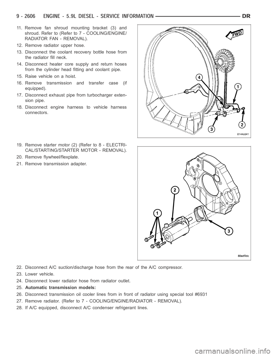
11. Remove fan shroud mounting bracket (3) and
shroud. Refer to (Refer to 7 - COOLING/ENGINE/
RADIATOR FAN - REMOVAL).
12. Remove radiator upper hose.
13. Disconnect the coolant recovery bottle hose from
the radiator fill neck.
14. Disconnect heater core supply and return hoses
from the cylinder head fitting and coolant pipe.
15. Raise vehicle on a hoist.
16. Remove transmission and transfer case (if
equipped).
17. Disconnect exhaust pipe from turbocharger exten-
sion pipe.
18. Disconnect engine harness to vehicle harness
connectors.
19. Remove starter motor (2) (Refer to 8 - ELECTRI-
CAL/STARTING/STARTER MOTOR - REMOVAL).
20. Remove flywheel/flexplate.
21. Remove transmission adapter.
22. Disconnect A/C suction/discharge hose from the rear of the A/C compressor.
23. Lower vehicle.
24. Disconnect lower radiator hose from radiator outlet.
25.Automatic transmission models:
26. Disconnect transmission oil cooler lines from in front of radiator using special tool #6931
27. Remove radiator. (Refer to 7 - COOLING/ENGINE/RADIATOR - REMOVAL).
28. If A/C equipped, disconnect A/C condenser refrigerant lines.
Page 1923 of 5267
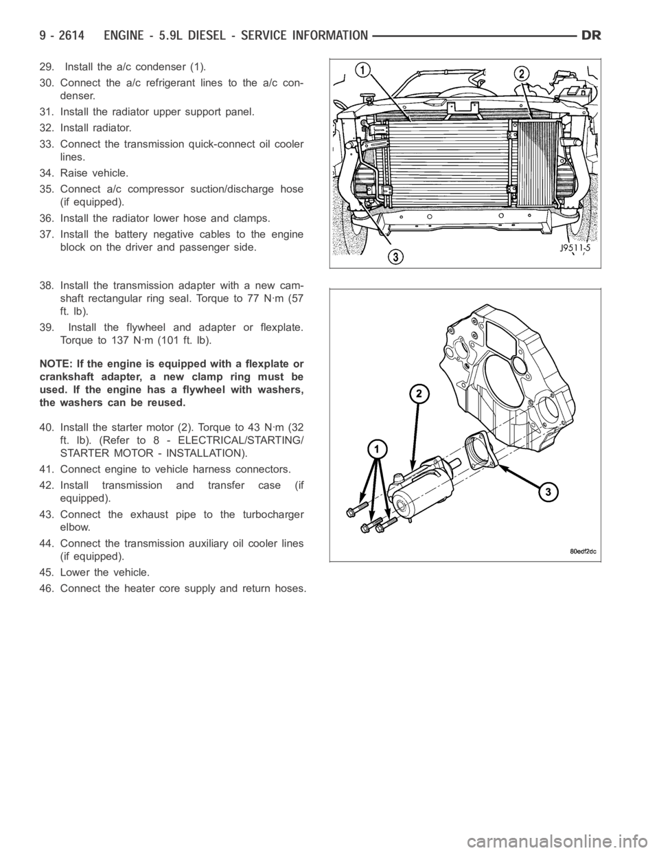
29. Install the a/c condenser (1).
30. Connect the a/c refrigerant lines to the a/c con-
denser.
31. Install the radiator upper support panel.
32. Install radiator.
33. Connect the transmission quick-connect oil cooler
lines.
34. Raise vehicle.
35. Connect a/c compressor suction/discharge hose
(if equipped).
36. Install the radiator lower hose and clamps.
37. Install the battery negative cables to the engine
block on the driver and passenger side.
38. Install the transmission adapter with a new cam-
shaft rectangular ring seal. Torque to 77 Nꞏm (57
ft. lb).
39. Install the flywheel and adapter or flexplate.
Torque to 137 Nꞏm (101 ft. lb).
NOTE: If the engine is equipped with a flexplate or
crankshaft adapter, a new clamp ring must be
used. If the engine has a flywheel with washers,
the washers can be reused.
40. Install the starter motor (2). Torque to 43 Nꞏm (32
ft. lb). (Refer to 8 - ELECTRICAL/STARTING/
STARTER MOTOR - INSTALLATION).
41. Connect engine to vehicle harness connectors.
42. Install transmission and transfer case (if
equipped).
43. Connect the exhaust pipe to the turbocharger
elbow.
44. Connect the transmission auxiliary oil cooler lines
(if equipped).
45. Lower the vehicle.
46. Connect the heater core supply and return hoses.