Page 2179 of 5267

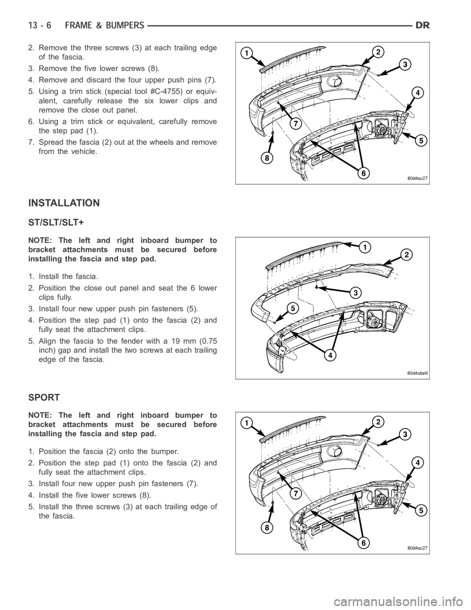
2. Remove the three screws (3) at each trailing edge
of the fascia.
3. Remove the five lower screws (8).
4. Remove and discard the four upper push pins (7).
5. Using a trim stick (special tool #C-4755) or equiv-
alent, carefully release the six lower clips and
remove the close out panel.
6. Using a trim stick or equivalent, carefully remove
the step pad (1).
7. Spread the fascia (2) out at the wheels and remove
from the vehicle.
INSTALLATION
ST/SLT/SLT+
NOTE: The left and right inboard bumper to
bracket attachments must be secured before
installing the fascia and step pad.
1. Install the fascia.
2. Position the close out panel and seat the 6 lower
clips fully.
3. Install four new upper push pin fasteners (5).
4. Position the step pad (1) onto the fascia (2) and
fully seat the attachment clips.
5. Align the fascia to the fender with a 19 mm (0.75
inch) gap and install the two screws at each trailing
edge of the fascia.
SPORT
NOTE: The left and right inboard bumper to
bracket attachments must be secured before
installing the fascia and step pad.
1. Position the fascia (2) onto the bumper.
2. Position the step pad (1) onto the fascia (2) and
fully seat the attachment clips.
3. Install four new upper push pin fasteners (7).
4. Install the five lower screws (8).
5. Install the three screws (3) at each trailing edge of
the fascia.
Page 2182 of 5267
FASCIA-FRONT SRT-10
REMOVAL
1. Remove the belly pan screws (1).
2. Remove the screws (1 & 2) from the wheel well.
Page 2186 of 5267
5. Install the screws (1 & 2) into the wheel well.
6. Install the screws (1) into the belly pan.
Page 2192 of 5267
2. Disconnect and isolate the battery negative cable.
3. Remove the front wheelhouse splash shield (Refer
to 23 - BODY/EXTERIOR/FRONT WHEELHOUSE
SPLASH SHIELD - REMOVAL).
4. Remove the fender (Refer to 23 - BODY/EXTERI-
OR/FRONT FENDER - REMOVAL).
5. Remove the A/C condenser, if required (Refer to 24
- HEATING & AIR CONDITIONING/PLUMBING/A/C
CONDENSER - REMOVAL).
6. Remove the A/C lines, if required. Refer to the
Heating and Air Conditioning section of the manual
for recommended procedures.
7. Remove the radiator assembly (4) (Refer to 7 -
COOLING/ENGINE/RADIATOR - REMOVAL).
Page 2200 of 5267

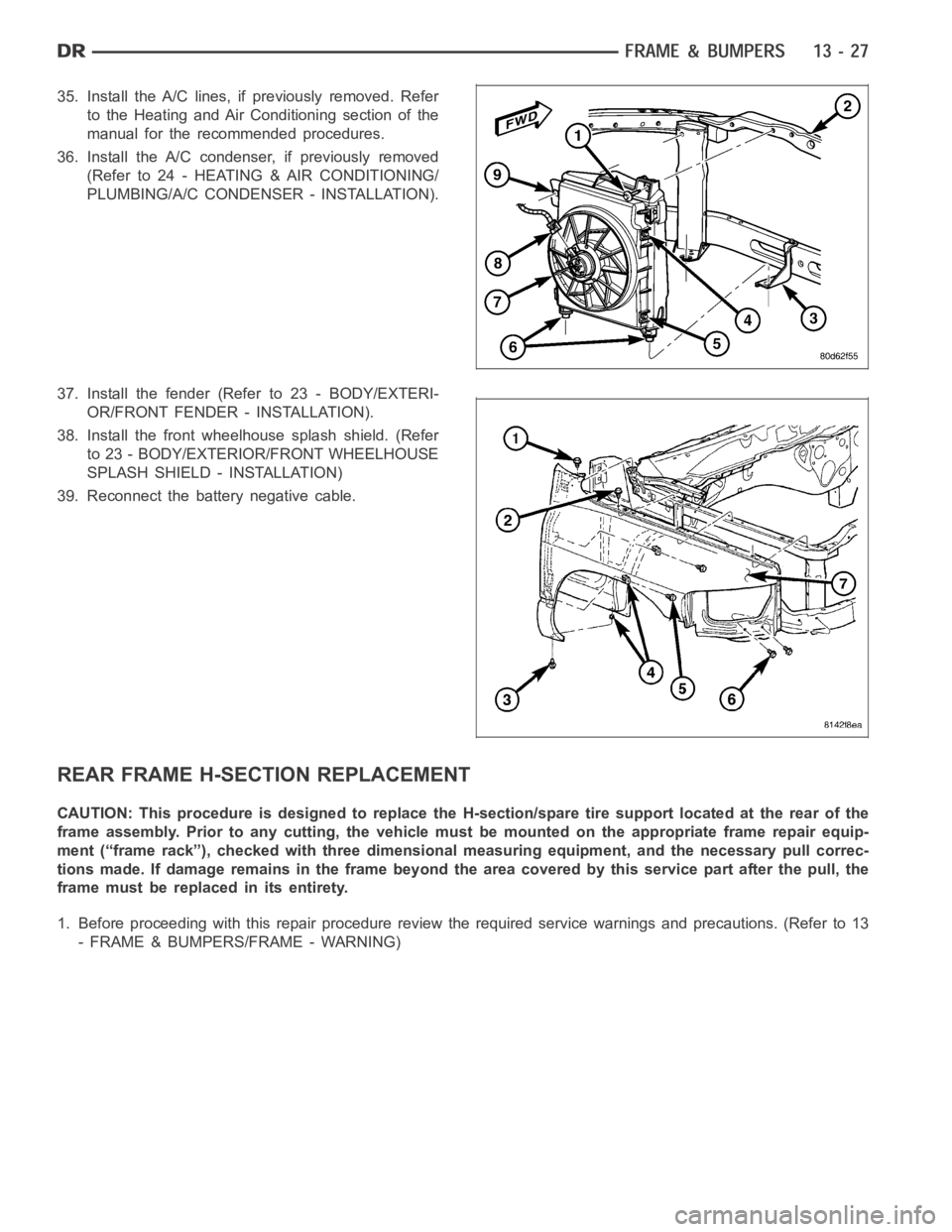
35. Install the A/C lines, if previously removed. Refer
to the Heating and Air Conditioning section of the
manual for the recommended procedures.
36. Install the A/C condenser, if previously removed
(Refer to 24 - HEATING & AIR CONDITIONING/
PLUMBING/A/C CONDENSER - INSTALLATION).
37. Install the fender (Refer to 23 - BODY/EXTERI-
OR/FRONT FENDER - INSTALLATION).
38. Install the front wheelhouse splash shield. (Refer
to 23 - BODY/EXTERIOR/FRONT WHEELHOUSE
SPLASH SHIELD - INSTALLATION)
39. Reconnect the battery negative cable.
REAR FRAME H-SECTION REPLACEMENT
CAUTION: This procedure is designed to replace the H-section/spare tire support located at the rear of the
frame assembly. Prior to any cutting, the vehicle must be mounted on the appropriate frame repair equip-
ment (“frame rack”), checked with three dimensional measuring equipment, and the necessary pull correc-
tions made. If damage remains in the frame beyond the area covered by this service part after the pull, the
frame must be replaced in its entirety.
1. Before proceeding with this repair procedure review the required service warnings and precautions. (Refer to 13
- FRAME & BUMPERS/FRAME - WARNING)
Page 2203 of 5267
7. Remove the rear leaf spring shackle bolts (6) and
let the axle rest on the ground.
8. Remove the spare wheel.
9.Removetheclip(2)andremovethesparetire
winch tube (3).
10. Remove the bolts (2) and remove the spare tire
winch (1).
11. Position the wire harness forward of the work
area.
Page 2207 of 5267

*First choice - Gas Metal Arc Welding Process:Butt joints - apply two layers (passes) of weld metal. First pass
should only fill approximately1⁄2the thickness. Vertical position welds - maintain electrode wire at leading edge of
weld puddle while traveling down hill to produce maximum penetration intothe sleeve. These techniques work for
FCAW as well.
**E7018new electrodes may be exposed to the atmosphere for up to ten hours with no harmful effect.
Reconditioning schedules should come from the manufacturer.
FRAME DIMENSIONS
NOTE: Frame dimensions are listed in metric scale. All dimensions are fromcenter to center of Principal
Locating Point (PLP), or from center to center of PLP and fastener location.
VEHICLE PREPARATION
Position the vehicle on a level work surface. Using screw or bottle jacks, adjust the vehicle PLP heights to the
specified dimension above a level work surface. Vertical dimensions can be taken from the work surface to the
locations indicated were applicable.
INDEX
DESCRIPTION FIGURE
1500 STANDARD CAB - 2 WHEEL DRIVE 1
1500 STANDARD CAB - 4 WHEEL DRIVE 2
1500 QUAD CAB - 2 WHEEL DRIVE 3
1500 QUAD CAB - 4 WHEEL DRIVE 4
140.5 IN WHEELBASE - HEAVY DUTY - 2 WHEEL DRIVE 5
140.5 IN WHEELBASE - HEAVY DUTY - 4 WHEEL DRIVE 6
160.5 IN WHEELBASE - 2500 - 2 WHEEL DRIVE 7
160.5 IN WHEELBASE - 2500 - 4 WHEEL DRIVE 8
160.5 IN WHEELBASE - 3500 - 2 WHEEL DRIVE 9
160.5 IN WHEELBASE - 3500 - 2 WHEEL DRIVE 10
Page 2208 of 5267
Fig. 1 1500 STANDARD CAB - 2 WHEEL DRIVE