Page 2419 of 5267
15. Install the steering column opening cover (1) and
kneeblocker (2) (Refer to 23 - BODY/INSTRU-
MENT PANEL/STEERING COLUMN OPENING
COVER - INSTALLATION).
16. Install the negative battery terminal.
17. Test the operation of the horn, Electronic PRNDL
Indicator, lights and any other functions that are
steering column operated.
SPECIFICATIONS
TORQUE
TORQUE SPECIFICATIONS
DESCRIPTION Nꞏm Ft. Lbs. In. Lbs.
Steering Coupling Upper
Pinch Bolt
LD & HD57 42 —
Steering Coupling Upper
Pinch Bolt
4X4 HD57 42 –
Steering Coupling Lower
Pinch Bolt
LD & HD57 42 —
Steering Coupling Lower
Pinch Bolt
SRT1038 28 —
Steering Coupling Lower
Pinch Bolt
4X4 HD28 21 250
Steering Wheel Bolt 61 45 —
Ignitiion Switch Mounting
Screws3—26
Tilt Lever Release
Mounting Screws4.5 — 40
Page 2421 of 5267

REMOVAL
SERVICE PRECAUTIONS
NOTE: The steering column on vehicles equipped with an automatic transmission is not equipped with an
internal locking shaft with the ignition cylinder. Alternative methods of locking the steering wheel for ser-
vice will have to be used.
To service the steering wheel, switches or airbag, Refer to Electrical Restraints and follow all WARNINGS and CAU-
TIONS.
WARNING: The airbag system is a sensitive, complex electro-mechanical unit. Before attempting to diag-
nose, remove or install the airbag system components you must first disconnect and isolate the battery
negative (ground) cable. Then wait two minutes for the system capacitor todischarge. Failure to do so
could result in accidental deployment of the airbag and possible personalinjury. The fasteners, screws, and
bolts, originally used for the airbag components, have special coatings and are specifically designed for the
airbag system. They must never be replaced with any substitutes. Anytime anew fastener is needed,
replace with the correct fasteners provided in the service package or fasteners listed in the parts books.
CAUTION: Do not hammer on steering column shaft. This may cause damage to the shaft or bearing.
CAUTION: Do not attempt to remove the pivot bolts to disassemble the tilting mechanism.
The ignition key must be in the key cylinder for cylinder removal. The key cylinder must be removed first before
removing ignition switch.
1. Remove the negative (ground) cable from the battery.
2. Disable the airbag, (Refer to 8 - ELECTRICAL/RESTRAINTS/DRIVER AIRBAG- REMOVAL).
3. Remove the kneeblocker and steering column reinforcement panel.
4. Remove the lower and upper shrouds.
5. Remove key cylinder. (Refer to 19 - STEERING/COLUMN/LOCK CYLINDER HOUSING - REMOVAL).
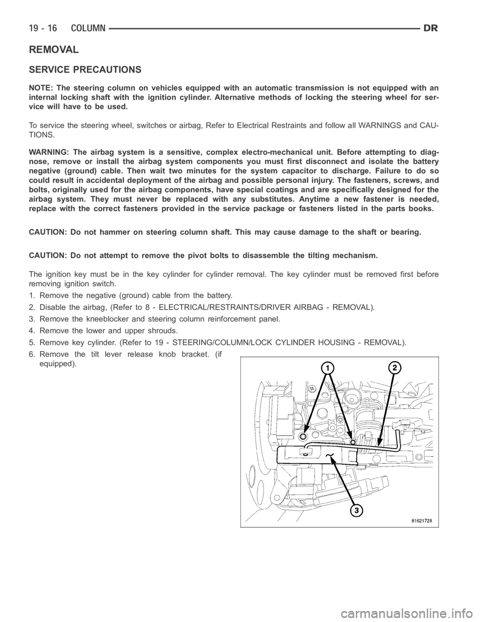
6. Remove the tilt lever release knob bracket. (if
equipped).
Page 2429 of 5267
STEERING WHEEL
REMOVAL
1. Disable and remove the driver’s side airbag. (Refer
to 8 - ELECTRICAL/RESTRAINTS/DRIVER AIR-
BAG - REMOVAL).
2. Partially remove the steering wheel bolt and leave
theboltinthecolumn.
3. Install puller CJ98-1 (2) or equivalent using the top
ofthebolttopushon.
4. Remove and discard the steering wheel bolt.
5. Remove the steering wheel (1).
INSTALLATION
NOTE: Do not reuse the old steering wheel bolt (a new bolt must be used)
1. Install steering wheel to the column
NOTE: Be certain that the steering wheel mounting bolt is tightened to the proper torque specification to
ensure proper clockspring operation.
2. Install the new steering wheel bolt. Tighten the bolt to 61 Nꞏm (45 ft. lbs.).
3. Install the driver’s side air bag. (Refer to 8 - ELECTRICAL/RESTRAINTS/DRIVER AIRBAG - INSTALLATION).
Page 2434 of 5267
7. Remove the blocker pin (1) from the inhibit link slot
(2) and remove the lever (3) by pulling forward
toward the steering wheel and to the left then
down.
INSTALLATION
1. Install the lever assembly (3) reversing the way it
came out using care to install the pin (2) in the
blocker to slider slot (1).
Page 2437 of 5267
UPPER STEERING COUPLING
REMOVAL
1. Disconnect the negative battery cable.
NOTE: The steering column on vehicles with an automatic transmission may not be equipped with an inter-
nal locking shaft that allows the ignition key cylinder to be locked with the key. Alternative methods of lock-
ing the steering wheel for service will have to be used.
2. Lock the steering wheel with the tire in the straight position.
3. Remove and discard the lower pinch bolt.
4. Lower the steering coupler shaft from the column.
5. Remove the upper steering coupling shaft (2) seal
by pushing in the four tags (1) securing it to the
panel.
6. Remove and discard the lower coupler pinch bolt
(1) from the lower steering coupling shaft (1).
7. Remove the upper steering coupling shaft (3) from
the vehicle.
Page 2438 of 5267
INSTALLATION
1. Install the upper steering coupling shaft (3) to the
vehicle.
2. Install the upper steering coupling shaft seal (2) by
pushing it in securing the four tangs (1) to the
panel.
NOTE: A new steering coupling shaft pinch bolt
for the upper and lower shafts must be used.
3. Install the steering coupler shaft (1) to the column.
4. Install the upper pinch bolt (3) use new bolt and
tighten to 57 N.m (42 ft.lbs).
5. Install the shaft to the lower coupler (1).
6. Install the lower pinch bolt (1) use new bolt and
tighten to 57 N.m (42 ft.lbs).
7. Unlock the steering wheel.
8. Reconnect the negative battery cable.
Page 2439 of 5267

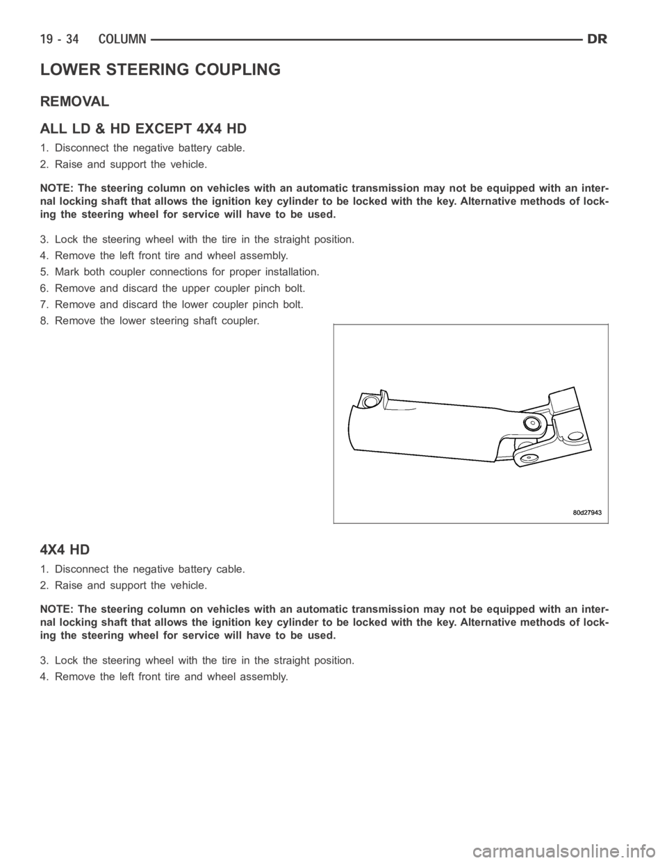
LOWER STEERING COUPLING
REMOVAL
ALLLD&HDEXCEPT4X4HD
1. Disconnect the negative battery cable.
2. Raise and support the vehicle.
NOTE: The steering column on vehicles with an automatic transmission may not be equipped with an inter-
nal locking shaft that allows the ignition key cylinder to be locked with the key. Alternative methods of lock-
ing the steering wheel for service will have to be used.
3. Lock the steering wheel with the tire in the straight position.
4. Remove the left front tire and wheel assembly.
5. Mark both coupler connections for proper installation.
6. Remove and discard the upper coupler pinch bolt.
7. Remove and discard the lower coupler pinch bolt.
8. Remove the lower steering shaft coupler.
4X4 HD
1. Disconnect the negative battery cable.
2. Raise and support the vehicle.
NOTE: The steering column on vehicles with an automatic transmission may not be equipped with an inter-
nal locking shaft that allows the ignition key cylinder to be locked with the key. Alternative methods of lock-
ing the steering wheel for service will have to be used.
3. Lock the steering wheel with the tire in the straight position.
4. Remove the left front tire and wheel assembly.
Page 2441 of 5267
INSTALLATION
ALLLD&HDEXCEPT4X4HD
1. Install the coupler to the steering rack & pinion
using the marks made in the removal process.
2. Install the coupler to the intermediate shaft using
the marks made in the removal process.
NOTE: New pinch bolts must be used for reinstal-
lation.
3. Install the lower pinch bolt and tighten to 57 Nꞏm
(42 ft. lbs.).SRT10. Tighten to 38 Nꞏm (28 ft.
lbs.).
4. Install the upper pinch bolt and tighten to 57 Nꞏm
(42 ft. lbs.).
5. Install the left front tire and wheel assembly (Refer to 22 - TIRES/WHEELS/WHEELS - STANDARD PROCE-
DURE).
6. Lower the vehicle.
7. Reconnect the negative battery cable.
8. Unlock the steering wheel.
4X4 HD
1. Install the coupler (2) to the steering gear (3).