2006 DODGE RAM SRT-10 wheel
[x] Cancel search: wheelPage 2922 of 5267
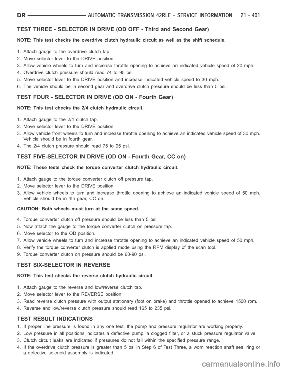
TEST THREE - SELECTOR IN DRIVE (OD OFF - Third and Second Gear)
NOTE: This test checks the overdrive clutch hydraulic circuit as well as the shift schedule.
1. Attach gauge to the overdrive clutch tap.
2. Move selector lever to the DRIVE position.
3. Allow vehicle wheels to turn and increase throttle opening to achieve anindicated vehicle speed of 20 mph.
4. Overdrive clutch pressure should read 74 to 95 psi.
5. Move selector lever to the DRIVE position and increase indicated vehicle speed to 30 mph.
6. The vehicle should be in second gearand overdrive clutch pressure shouldbelessthan5psi.
TEST FOUR - SELECTOR IN DRIVE (OD ON - Fourth Gear)
NOTE: This test checks the 2/4 clutch hydraulic circuit.
1. Attach gauge to the 2/4 clutch tap.
2. Move selector lever to the DRIVE position.
3. Allow vehicle front wheels to turn and increase throttle opening to achieve an indicated vehicle speed of 30 mph.
Vehicleshouldbeinfourthgear.
4. The 2/4 clutch pressure should read 75 to 95 psi.
TEST FIVE-SELECTOR IN DRIVE (OD ON - Fourth Gear, CC on)
NOTE: These tests check the torque converter clutch hydraulic circuit.
1. Attach gauge to the torque converter clutch off pressure tap.
2. Move selector lever to the DRIVE position.
3. Allow vehicle wheels to turn and increase throttle opening to achieve anindicated vehicle speed of 50 mph.
Vehicle should be in 4th gear, CC on.
CAUTION: Both wheels must turn at the same speed.
4. Torque converter clutch off pressure should be less than 5 psi.
5. Now attach the gauge to the torque converter clutch on pressure tap.
6. Move selector to the OD position.
7. Allow vehicle wheels to turn and increase throttle opening to achieve anindicated vehicle speed of 50 mph.
8. Verify the torque converter clutch is applied mode using the RPM displayof the scan tool.
9. Torque converter clutch on pressure should be 60-90 psi.
TEST SIX-SELECTOR IN REVERSE
NOTE: This test checks the reverse clutch hydraulic circuit.
1. Attach gauge to the reverse and low/reverse clutch tap.
2. Move selector lever to the REVERSE position.
3. Read reverse clutch pressure with output stationary (foot on brake) andthrottle opened to achieve 1500 rpm.
4. Reverse and low/reverse clutch pressure should read 165 to 235 psi.
TEST RESULT INDICATIONS
1. If proper line pressure is found in any one test, the pump and pressure regulator are working properly.
2. Low pressure in all positions indicates a defective pump, a clogged filter, or a stuck pressure regulator valve.
3. Clutch circuit leaks are indicated if pressures do not fall within the specified pressure range.
4. If the overdrive clutch pressure is greater than 5 psi in Step 6 of Test Three, a worn reaction shaft seal ring or
a defective solenoid assembly is indicated.
Page 2923 of 5267
5. Iftheunderdriveclutchpressureisgreaterthan5psiinStep4ofTestTwo-A, a defective solenoid/pressure
switch assembly or controller is the cause.
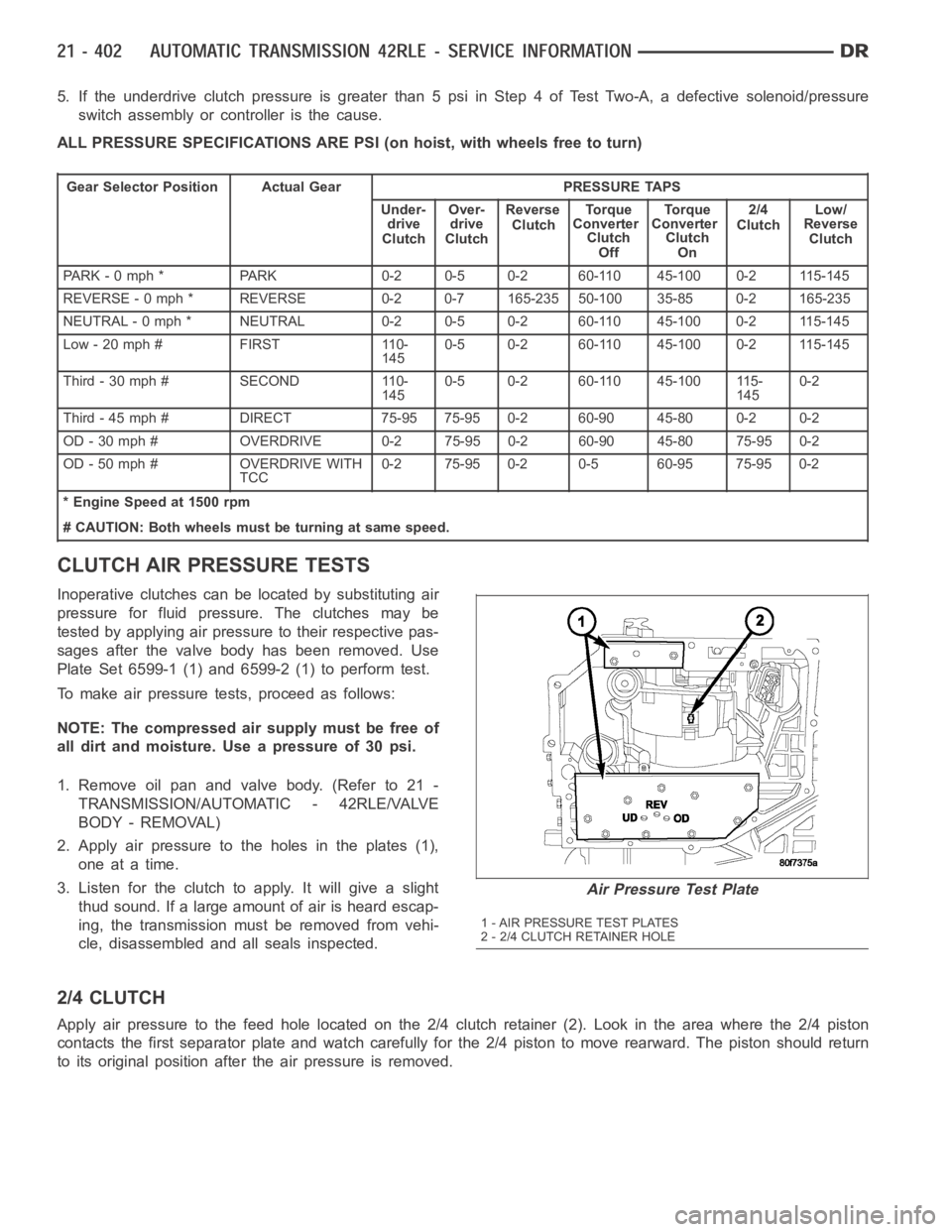
ALL PRESSURE SPECIFICATIONS ARE PSI (on hoist, with wheels free to turn)
Gear Selector Position Actual Gear PRESSURE TAPS
Under-
drive
ClutchOver-
drive
ClutchReverse
ClutchTo r q u e
Converter
Clutch
OffTo r q u e
Converter
Clutch
On2/4
ClutchLow/
Reverse
Clutch
PARK - 0 mph * PARK 0-2 0-5 0-2 60-110 45-100 0-2 115-145
REVERSE - 0 mph * REVERSE 0-2 0-7 165-235 50-100 35-85 0-2 165-235
NEUTRAL - 0 mph * NEUTRAL 0-2 0-5 0-2 60-110 45-100 0-2 115-145
Low - 20 mph # FIRST 110-
1450-5 0-2 60-110 45-100 0-2 115-145
Third-30mph# SECOND 110-
1450-5 0-2 60-110 45-100 115-
1450-2
Third - 45 mph # DIRECT 75-95 75-95 0-2 60-90 45-80 0-2 0-2
OD - 30 mph # OVERDRIVE 0-2 75-95 0-2 60-90 45-80 75-95 0-2
OD - 50 mph # OVERDRIVE WITH
TCC0-2 75-95 0-2 0-5 60-95 75-95 0-2
* Engine Speed at 1500 rpm
# CAUTION: Both wheels must be turning at same speed.
CLUTCH AIR PRESSURE TESTS
Inoperative clutches can be located by substituting air
pressure for fluid pressure. The clutches may be
tested by applying air pressure to their respective pas-
sages after the valve body has been removed. Use
Plate Set 6599-1 (1) and 6599-2 (1) to perform test.
To make air pressure tests, proceed as follows:
NOTE: The compressed air supply must be free of
all dirt and moisture. Use a pressure of 30 psi.
1. Remove oil pan and valve body. (Refer to 21 -
TRANSMISSION/AUTOMATIC - 42RLE/VALVE
BODY - REMOVAL)
2. Apply air pressure to the holes in the plates (1),
one at a time.
3. Listen for the clutch to apply. It will give a slight
thud sound. If a large amount of air is heard escap-
ing, the transmission must be removed from vehi-
cle, disassembled and all seals inspected.
2/4 CLUTCH
Apply air pressure to the feed hole located on the 2/4 clutch retainer (2). Look in the area where the 2/4 piston
contacts the first separator plate and watch carefully for the 2/4 piston tomoverearward.Thepistonshouldreturn
to its original position after the air pressure is removed.
Air Pressure Test Plate
1 - AIR PRESSURE TEST PLATES
2 - 2/4 CLUTCH RETAINER HOLE
Page 2962 of 5267
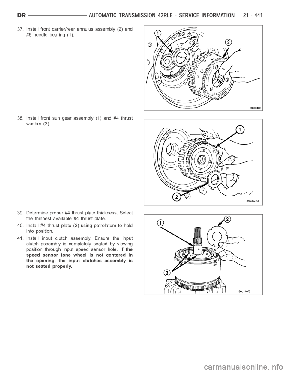
37. Install front carrier/rear annulus assembly (2) and
#6 needle bearing (1).
38. Install front sun gear assembly (1) and #4 thrust
washer (2).
39. Determine proper #4 thrust plate thickness. Select
the thinnest available #4 thrust plate.
40. Install #4 thrust plate (2) using petrolatum to hold
into position.
41. Install input clutch assembly. Ensure the input
clutch assembly is completely seated by viewing
position through input speed sensor hole.If the
speed sensor tone wheel is not centered in
the opening, the input clutches assembly is
not seated properly.
Page 3068 of 5267
TURBINE
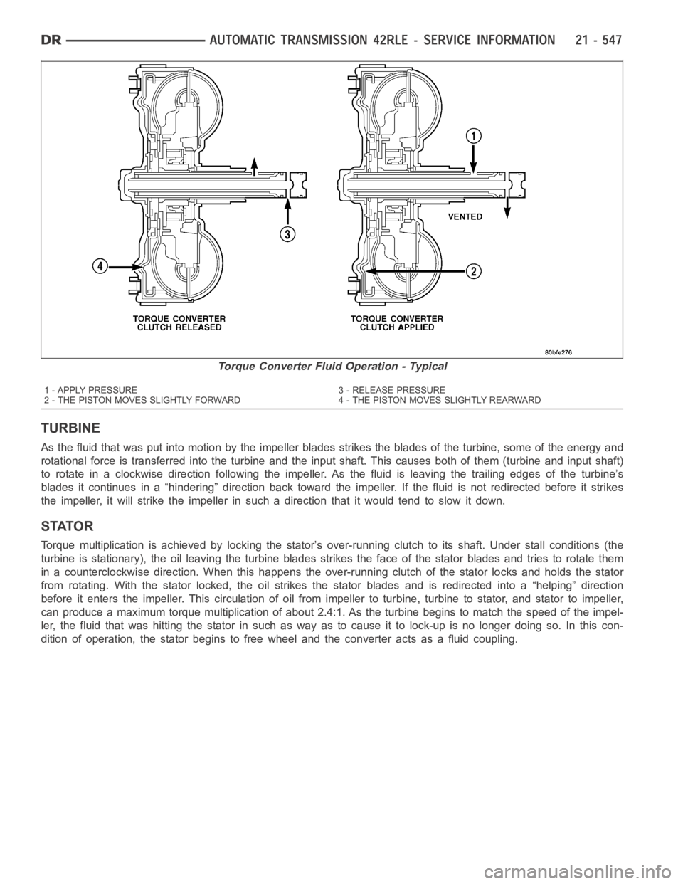
As the fluid that was put into motion bythe impeller blades strikes the blades of the turbine, some of the energy and
rotational force is transferred into the turbine and the input shaft. Thiscauses both of them (turbine and input shaft)
to rotate in a clockwise direction following the impeller. As the fluid is leaving the trailing edges of the turbine’s
blades it continues in a “hindering” direction back toward the impeller. If the fluid is not redirected before it strikes
the impeller, it will strike the impeller in such a direction that it would tend to slow it down.
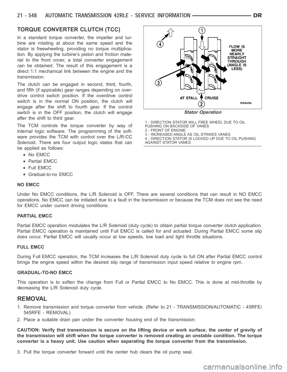
STATOR
Torque multiplication is achieved by locking the stator’s over-running clutch to its shaft. Under stall conditions (the
turbine is stationary), the oil leaving the turbine blades strikes the face of the stator blades and tries to rotate them
in a counterclockwise direction. When this happens the over-running clutch of the stator locks and holds the stator
from rotating. With the stator locked, the oil strikes the stator blades and is redirected into a “helping” direction
before it enters the impeller. This circulation of oil from impeller to turbine, turbine to stator, and stator to impeller,
can produce a maximum torque multiplicationofabout2.4:1.Astheturbinebegins to match the speed of the impel-
ler, the fluid that was hitting the stator in such as way as to cause it to lock-up is no longer doing so. In this con-
dition of operation, the stator begins to free wheel and the converter actsas a fluid coupling.
Torque Converter Fluid Operation - Typical
1 - APPLY PRESSURE 3 - RELEASE PRESSURE
2 - THE PISTON MOVES SLIGHTLY FORWARD 4 - THE PISTON MOVES SLIGHTLY REARWARD
Page 3069 of 5267
TORQUE CONVERTER CLUTCH (TCC)
In a standard torque converter, the impeller and tur-
bine are rotating at about the same speed and the
stator is freewheeling, providing no torque multiplica-
tion. By applying the turbine’s piston and friction mate-
rial to the front cover, a total converter engagement
can be obtained. The result of this engagement is a
direct 1:1 mechanical link between the engine and the
transmission.
The clutch can be engaged in second, third, fourth,
and fifth (if appicable) gear ranges depending on over-
drive control switch position. If the overdrive control
switch is in the normal ON position, the clutch will
engage after the shift to fourth gear. If the control
switch is in the OFF position, the clutch will engage
after the shift to third gear.
The TCM controls the torque converter by way of
internal logic software. The programming of the soft-
ware provides the TCM with control over the L/R-CC
Solenoid. There are four output logic states that can
be applied as follows:
No EMCC
Partial EMCC
Full EMCC
Gradual-to-no EMCC
NO EMCC
Under No EMCC conditions, the L/R Solenoid is OFF. There are several conditions that can result in NO EMCC
operations. No EMCC can be initiated due to a fault in the transmission or because the TCM does not see the need
for EMCC under current driving conditions.
PARTIAL EMCC
Partial EMCC operation modulates the L/R Solenoid (duty cycle) to obtain partial torque converter clutch application.
Partial EMCC operation is maintaineduntil Full EMCC is called for and actuated. During Partial EMCC some slip
does occur. Partial EMCC will usually occur at low speeds, low load and light throttle situations.
FULL EMCC
During Full EMCC operation, the TCM increases the L/R Solenoid duty cycle to full ON after Partial EMCC control
brings the engine speed within the desired slip range of transmission input speed relative to engine rpm.
GRADUAL-TO-NO EMCC
This operation is to soften the change from Full or Partial EMCC to No EMCC. This is done at mid-throttle by
decreasing the L/R Solenoid duty cycle.
REMOVAL
1. Remove transmission and torque converter from vehicle. (Refer to 21 - TRANSMISSION/AUTOMATIC - 45RFE/
545RFE - REMOVAL)
2. Place a suitable drain pan under the converter housing end of the transmission.
CAUTION: Verify that transmission is secure on the lifting device or work surface, the center of gravity of
the transmission will shift when the torque converter is removed creatingan unstable condition. The torque
converter is a heavy unit. Use caution when separating the torque converter from the transmission.
3. Pull the torque converter forward until the center hub clears the oil pumpseal.
Stator Operation
1 - DIRECTION STATOR WILL FREE WHEEL DUE TO OIL
PUSHING ON BACKSIDE OF VANES
2-FRONTOFENGINE
3 - INCREASED ANGLE AS OIL STRIKES VANES
4 - DIRECTION STATOR IS LOCKED UP DUE TO OIL PUSHING
AGAINST STATOR VANES
Page 3142 of 5267
When Monitored:
The transmission gear ratio is monitored continuously while the transmission is in gear.
Set Condition:
If there is an excessive change in output RPM in any gear. This DTC can take upto five minutes of problem
identification beforeilluminating the MIL.
Possible Causes
(T14) OUTPUT SPEED SENSOR SIGNAL CIRCUIT OPEN
(T13) SPEED SENSOR GROUND CIRCUIT OPEN
(T14) OUTPUT SPEED SENSOR SIGNAL CIRCUIT SHORT TO GROUND
(T13) SPEED SENSOR GROUND CIRCUIT SHORT TO GROUND
(T14) OUTPUT SPEED SENSOR SIGNAL CIRCUIT SHORT TO VOLTAGE
(T13) SPEED SENSOR GROUND CIRCUIT SHORT TO VOLTAGE
OUTPUT SPEED SENSOR
POWERTRAIN CONTROL MODULE
Always perform the 45RFE/545RFE Pre-Diagnostic Troubleshooting Procedure before proceeding. (Refer to
21 - TRANSMISSION/TRANSAXLE/AUTOMATIC - 45RFE/545RFE - STANDARD PROCEDURE)
Theory of Operation
The transmission system uses two speed sensors, one to measure input RPM and one to measure output RPM.
These inputs are essential for proper transmission operation. Therefore, the integrity of this data is verified through
the following checks:
1) When in gear, if the gear ratio does not compare to a known gear ratio, the corresponding in-gear trouble code
is set (codes P0731 through P0736).
2) An excessive change in input or output speeds indicating signal intermittent will result in codes P0715 and/or
P0720 being set.
3) If the common speed sensor ground circuit is lost, both sensor inputs will read the signal from the input speed
sensor at idle in neutral. Since the input speed sensor has 60 teeth and the output speed sensor has 30 teeth, this
results in a an apparent speed ratio of 1:2 and may cause the DTC P1794 to set.
Diagnostic Test
1.CHECK TO SEE IF DTC P0720 IS CURRENT
Turn the ignition off to the lock position.
CAUTION: Properly support the vehicle and raise all drive wheels off the ground.
Release the parking brake.
Start the engine in park.
Place the transmission gear selector in drive, release foot from brake.
WARNING: Be sure to keep hands and feet clear of rotation wheels.
With the scan tool, monitor the Output Speed Sensor RPM.
Is the Output Speed Sensor RPM below 100 RPM?
Ye s>>
Go To 2
No>>
Go To 9
Page 3152 of 5267
P0732-GEAR RATIO ERROR IN 2ND
For a complete wiring diagramRefer to Section 8W
When Monitored:
Continuously with the ignition on, engine running, with the transmissionin gear.
Set Condition:
If the ratio of the Input RPM to the Output RPM does not match the current gearratio. This DTC can take up
to five minutes of problem identification before illuminating the MIL
Possible Causes
RELATED DTC’S PRESENT
INPUT SPEED SENSOR OR WIRING
LOW FLUID LEVEL
CRACKED OR MIS-INSTALLED PRIMARY OIL FILTER OR SEAL
WORN SOLENOID SWITCH VALVE OR PLUGS
STUCK OR STICKING MAIN REGULATOR VALVE
BURNED UD OR 2C CLUTCH
CUT 2C OR UD PISTON SEAL
BROKEN 2C PISTON CASTING
BROKEN OR MISSING 2C BLEED ORIFICE
BROKEN OR MISSING UD BLEED ORIFICE
CUT 2C OR UD ACCUMULATOR PISTON SEAL
CRACKED 2C OR UD ACCUMULATOR PISTON
CUT OR MISSING #5 OR #7 CHECK BALL
TRANSMISSION SOLENOID/TRS ASSEMBLY
BROKEN WELD - REACTION CARRIER TO REVERSE SUN GEAR
MISSING TEETH ON INPUT CLUTCH HUB TONE WHEEL
Always perform the 45RFE/545RFE Pre-Diagnostic Troubleshooting Procedure before proceeding. (Refer to
21 - TRANSMISSION/TRANSAXLE/AUTOMATIC - 45RFE/545RFE - STANDARD PROCEDURE)
Theory of Operation
The transmission system uses two speed sensors, one to measure input RPM and one to measure output RPM.
These inputs are essential for proper transmission operation. Therefore, the integrity of this data is verified through
the following checks:
1) Once in a particular gear, if the gear ratio varies from the correct gear ratio, the corresponding in-gear trouble
code is set (DTCs P0731-36).
2) An excessive change in input or output speeds indicating signal intermittent may result in the DTCs P0715 and/or
P0720 being set.
3) If the common speed sensor ground circuit is lost, both sensor inputs will read the pulses from the input speed
sensor when at a stop in neutral. Since the input speed sensor reads 60 teethfrom the input clutch hub and the
output speed sensor reads 30 teeth from the park gear, the result is an apparent speed ratio of 1:2 and may cause
the DTC P1794 to set.
Page 3321 of 5267

P1736-GEAR RATIO ERROR IN 2ND PRIME
For a complete wiring diagramRefer to Section 8W.
When Monitored:
Continuously with the ignition on, engine running, with the transmissionin gear.
Set Condition:
If the ratio of the Input RPM to the Output RPM does not match the current gearratio. This DTC can take up
to five minutes of problem identification before illuminating the MIL
Possible Causes
RELATED DTC’S PRESENT
INPUT SPEED SENSOR OR WIRING
LOW FLUID LEVEL
CRACKED OR MIS-INSTALLED PRIMARY OIL FILTER OR SEAL
WORN SOLENOID SWITCH VALVE OR PLUGS
STUCK OR STICKING MAIN REGULATOR VALVE
BURNED UD OR 4C CLUTCH
CUT 4C OR UD PISTON SEAL
BROKEN 4C PISTON CASTING
BROKEN OR MISSING 4C BLEED ORIFICE
BROKEN OR MISSING UD BLEED ORIFICE
CUT 4C OR UD ACCUMULATOR PISTON SEAL
CRACKED 4C OR UD ACCUMULATOR PISTON
EXTRA CHECK BALL IN PASSAGE DOWNSTREAM OF #7 CHECK BALL POCKET
TRANSMISSION SOLENOID/TRS ASSEMBLY
BROKEN WELD - REACTION CARRIER TO REVERSE SUN GEAR
MISSING TEETH ON INPUT CLUTCH HUB TONE WHEEL
Always perform the 45RFE/545RFE Pre-Diagnostic Troubleshooting Procedure before proceeding. (Refer to
21 - TRANSMISSION/TRANSAXLE/AUTOMATIC - 45RFE/545RFE - STANDARD PROCEDURE)
Theory of Operation
The transmission system uses two speed sensors, one to measure input RPM and one to measure output RPM.
These inputs are essential for proper transmission operation. Therefore, the integrity of this data is verified through
the following checks:
1) When in gear, if the gear ratio does not compare to a known gear ratio, the corresponding in-gear trouble code
is set (DTCs P0731-36).
2) An excessive change in input or output speeds indicating signal intermittent which may result in the DTCs P0715
and/or P0720 to set.
3) If the common speed sensor ground circuit is lost, both sensor inputs will read the signal from the input speed
sensor at idle in neutral. Since the input speed sensor reads 60 teeth from the input clutch hub and the output
speed sensor reads 30 teeth from the park gear, the result is an apparent speed ratio of 1:2 and may cause the
DTC P1794 to set when at a stop.