2006 DODGE RAM SRT-10 wheel
[x] Cancel search: wheelPage 3801 of 5267
5. Line pressure should be 54-60 psi (372-414 kPa) with throttle lever forward and gradually increase to 90-96 psi
(621-662 kPa) as lever is moved rearward.
Test Three - Transmission In D Range Third Gear
This test checks pressure regulation and condition of the clutch circuits. Both test gauges are required for this test.
1. Turn OD switch off.
2. Leave vehicle on hoist and leave Oil Pressure Gauge C-3292 in place at accumulator port.
3. Move Oil Pressure Gauge C-3293-SP over to front servo port for this test.
4. Have helper start and run engine at 1600 rpm for this test.
5. Move transmission shift lever two detents rearward from full forward position. This is D range.
6. Read pressures on both gauges as transmission throttle lever is gradually moved from full forward to full rear-
ward position:
Line pressure at accumulator in D range third gear, should be 54-60 psi (372-414 kPa) with throttle lever for-
ward and increase as lever is moved rearward.
Front servo pressure in D range third gear, should be within 3 psi (21 kPa) ofline pressure up to kickdown
point.
Test Four - Transmission In Reverse
This test checks pump output, pressure regulation and the front clutch andrear servo circuits. Use 300 psi Oil
Pressure Gauge C-3293-SP for this test.
1. Leave vehicle on hoist and leave Oil Pressure Gauge C-3292 in place at accumulator port.
2. Move 300 psi Oil Pressure Gauge C-3293-SP back to rear servo port.
3. Have helper start and run engine at 1600 rpm for test.
4. Move transmission shift lever four detents rearward from full forward position. This is Reverse range.
5. Move transmission throttle lever fully forward then fully rearward andnote reading at Gauge C-3293-SP.
6. Pressure should be 145 - 175 psi (1000-1207 kPa) with throttle lever forward and increase to 230 - 280 psi
(1586-1931 kPa) as lever is gradually moved rearward.
Test Five - Governor Pressure
This test checks governor operation by measuring governor pressure response to changes in vehicle speed. It is
usually not necessary to check governor operation unless shift speeds areincorrect or if the transmission will not
downshift. The test should be performed on the road or on a hoist that will allow the rear wheels to rotate freely.
1. Move 100 psi Oil Pressure Gauge C-3292 to governor pressure port.
2. Move transmission shift lever two detents rearward from full forward position. This is D range.
3. Have helper start and run engine at curb idle speed. Then firmly apply service brakes so wheels will not rotate.
4. Note governor pressure:
Governor pressure should be no more than 20.6 kPa (3 psi) at curb idle speed and wheels not rotating.
If pressure exceeds 20.6 kPa (3 psi), a fault exists in governor pressure control system.
5. Release brakes, slowly increase engine speed, and observe speedometerand pressure test gauge (do not
exceed 30 mph on speedometer). Governor pressure should increase in proportion to vehicle speed. Or approx-
imately 6.89 kPa (1 psi) for every 1 mph.
6. Governor pressure rise should be smooth and drop back to no more than 20.6kPa (3 psi), after engine returns
to curb idle and brakes are applied to prevent wheels from rotating.
7. Compare results of pressure test with analysis chart.
Test Six - Transmission In Overdrive Fourth Gear
This test checks line pressure at the overdrive clutch in fourth gear range. Use 300 psi Oil Pressure Gauge
C-3293-SP for this test. The test should be performed on the road or on a chassis dyno.
1. Remove tachometer; it is not needed for this test.
2. Move 300 psi Oil Pressure Gauge to overdrive clutch pressure test port. Then remove other gauge and reinstall
test port plug.
Page 3870 of 5267
WIDE OPEN THROTTLE OPERATION
In wide-open throttle (WOT) mode, adaptive memory in the PCM assures that up-shifts occur at the preprogrammed
optimum speed. WOT operation is determined from the throttle position sensor, which is also a part of the emission
control system. The initial setting for the WOT upshift is below the optimum engine speed. As WOT shifts are
repeated, the PCM learns the time required to complete the shifts by comparing the engine speed when the shifts
occur to the optimum speed. After each shift, the PCM adjusts the shift point until the optimum speed is reached.
The PCM also considers vehicle loading, grade and engine performance changes due to high altitude in determining
when to make WOT shifts. It does this by measuring vehicle and engine acceleration and then factoring in the shift
time.
TRANSFER CASE LOW RANGE OPERATION
On four-wheel drive vehicles operating in low range, the engine can accelerate to its peak more rapidly than in
Normal range, resulting in delayed shifts and undesirable engine
flare.The low range governor pressure curve is
also higher than normal to initiate upshifts sooner. The PCM compares electronic vehicle speed signal used by the
speedometer to the transmission output shaft speed signal to determine when the transfer case is in low range.
REMOVAL
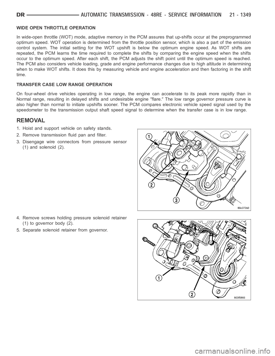
1. Hoist and support vehicle on safety stands.
2. Remove transmission fluid pan and filter.
3. Disengage wire connectors from pressure sensor
(1) and solenoid (2).
4. Remove screws holding pressure solenoid retainer
(1) to governor body (2).
5. Separate solenoid retainer from governor.
Page 3923 of 5267
RETAINER-OVERRUNNING CLUTCH CAM/OVERDRIVE PISTON
DESCRIPTION
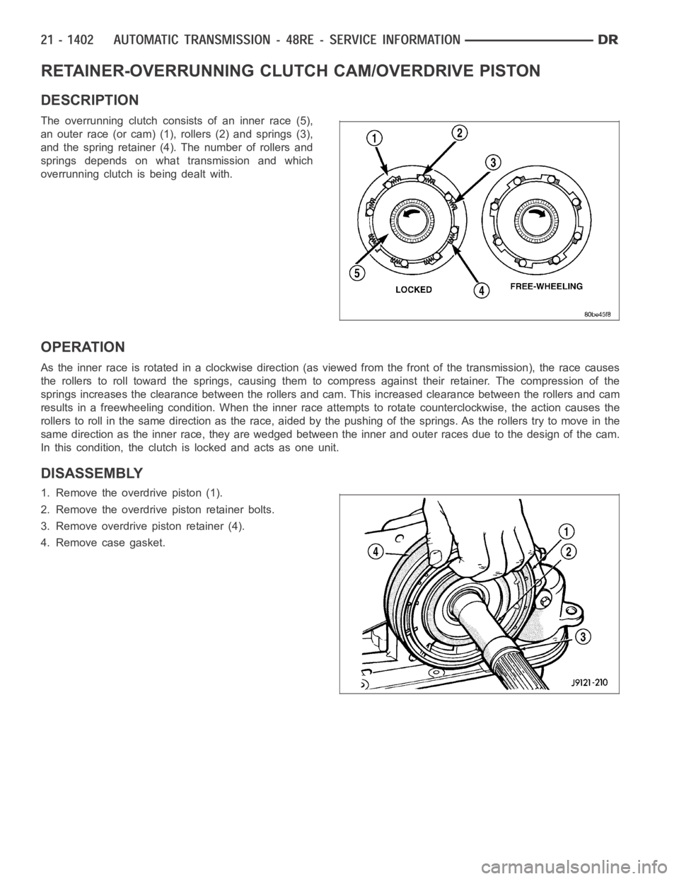
The overrunning clutch consists of an inner race (5),
an outer race (or cam) (1), rollers (2) and springs (3),
and the spring retainer (4). The number of rollers and
springs depends on what transmission and which
overrunning clutch is being dealt with.
OPERATION
Astheinnerraceisrotatedinaclockwisedirection(asviewedfromthefront of the transmission), the race causes
the rollers to roll toward the springs, causing them to compress against their retainer. The compression of the
springs increases the clearance between the rollers and cam. This increased clearance between the rollers and cam
results in a freewheeling condition. When the inner race attempts to rotate counterclockwise, the action causes the
rollers to roll in the same direction as the race, aided by the pushing of thesprings. As the rollers try to move in the
same direction as the inner race, they are wedged between the inner and outer races due to the design of the cam.
In this condition, the clutch is locked and acts as one unit.
DISASSEMBLY
1. Remove the overdrive piston (1).
2. Remove the overdrive piston retainer bolts.
3. Remove overdrive piston retainer (4).
4. Remove case gasket.
Page 3957 of 5267
STATOR
Torque multiplication is achieved by locking the sta-
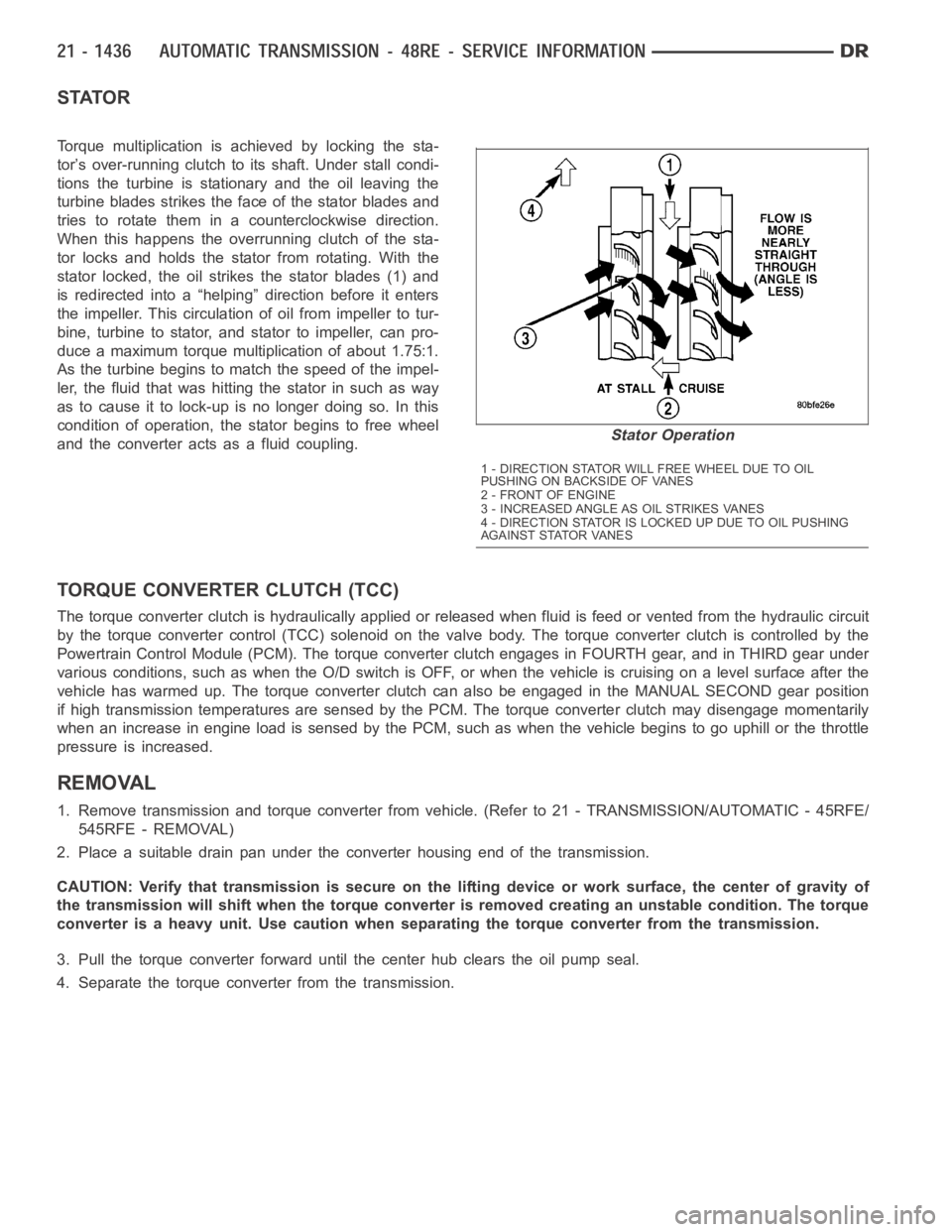
tor’s over-running clutch to its shaft. Under stall condi-
tions the turbine is stationary and the oil leaving the
turbine blades strikes the face of the stator blades and
tries to rotate them in a counterclockwise direction.
When this happens the overrunning clutch of the sta-
tor locks and holds the stator from rotating. With the
stator locked, the oil strikes the stator blades (1) and
is redirected into a “helping” direction before it enters
the impeller. This circulation of oil from impeller to tur-
bine, turbine to stator, and stator to impeller, can pro-
duce a maximum torque multiplication of about 1.75:1.
As the turbine begins to match the speed of the impel-
ler, the fluid that was hitting the stator in such as way
as to cause it to lock-up is no longer doing so. In this
condition of operation, the stator begins to free wheel
and the converter acts as a fluid coupling.
TORQUE CONVERTER CLUTCH (TCC)
The torque converter clutch is hydraulically applied or released when fluid is feed or vented from the hydraulic circuit
by the torque converter control (TCC) solenoid on the valve body. The torque converter clutch is controlled by the
Powertrain Control Module (PCM). The torque converter clutch engages in FOURTH gear, and in THIRD gear under
various conditions, such as when the O/D switch is OFF, or when the vehicle is cruising on a level surface after the
vehicle has warmed up. The torque converter clutch can also be engaged in the MANUAL SECOND gear position
if high transmission temperatures are sensed by the PCM. The torque converter clutch may disengage momentarily
when an increase in engine load is sensed by the PCM, such as when the vehiclebegins to go uphill or the throttle
pressure is increased.
REMOVAL
1. Remove transmission and torque converter from vehicle. (Refer to 21 - TRANSMISSION/AUTOMATIC - 45RFE/
545RFE - REMOVAL)
2. Place a suitable drain pan under the converter housing end of the transmission.
CAUTION: Verify that transmission is secure on the lifting device or work surface, the center of gravity of
the transmission will shift when the torque converter is removed creatingan unstable condition. The torque
converter is a heavy unit. Use caution when separating the torque converter from the transmission.
3. Pull the torque converter forward until the center hub clears the oil pumpseal.
4. Separate the torque converter from the transmission.
Stator Operation
1 - DIRECTION STATOR WILL FREE WHEEL DUE TO OIL
PUSHING ON BACKSIDE OF VANES
2-FRONTOFENGINE
3 - INCREASED ANGLE AS OIL STRIKES VANES
4 - DIRECTION STATOR IS LOCKED UP DUE TO OIL PUSHING
AGAINST STATOR VANES
Page 4083 of 5267
TRANSFER CASE VERIFICATION TEST
1.
Disconnect all jumper wires and reconnect all previously disconnected components and connectors.
With the scan tool, select clear Stored DTCs.
Make sure that all accessories are turned off and that the battery is fully charged.
Test drive the vehicle in each Transfer Case range and verify proper operation in each range.
To select or deselect 2WD, AWD or 4HI mode, vehicle speed must be below 88 Kmh(55 mph) with all wheels
at vehicle speed.
Shifts will not take place with a wheel speed difference of greater than 21 Kmh (13 mph) between the front
and rear wheels.
To select or deselect 4LO (if equipped), vehicle speed must be below 5 Kmh (3mph) with the ignition ON and
the transmission in neutral (auto trans) or the clutch pedal pressed (man trans).
To select or deselect Transfer Case Neutral, vehicle speed must be 0 Kmh (0 mph) with the ignition ON,
engine OFF, the brake pedal applied, and the transmission in neutral (autotrans) or the clutch pedal pressed
(man trans). Press the Neutral button (if equipped) on the Transfer Case Selector Switch until the Neutral Indi-
cator is illuminated.
WARNING: Apply the parking brake. The vehicle may roll with the Transfer Case in neutral.
To verify that the Transfer Case is in Neutral, shift the automatic transmission into reverse and release the
brake pedal for three seconds or shift the manual transmission into gear andslowlyreleasetheclutchpedal.
There should be no vehicle movement if the Transfer Case is in Neutral.
With the scan tool, select View DTCs in the Totally Integrated Power Module(TIPM) and in the Instrument Cluster.
Are there any DTCs present in the Totally Integrated Power Module (TIPM) orin the Instrument Cluster?
Ye s>>
Return to the symptom list and perform the appropriate diagnostic test.
No>>
Repair is complete.
Page 4085 of 5267
TRANSFER CASE - NV241 GENII - SERVICE INFORMATION
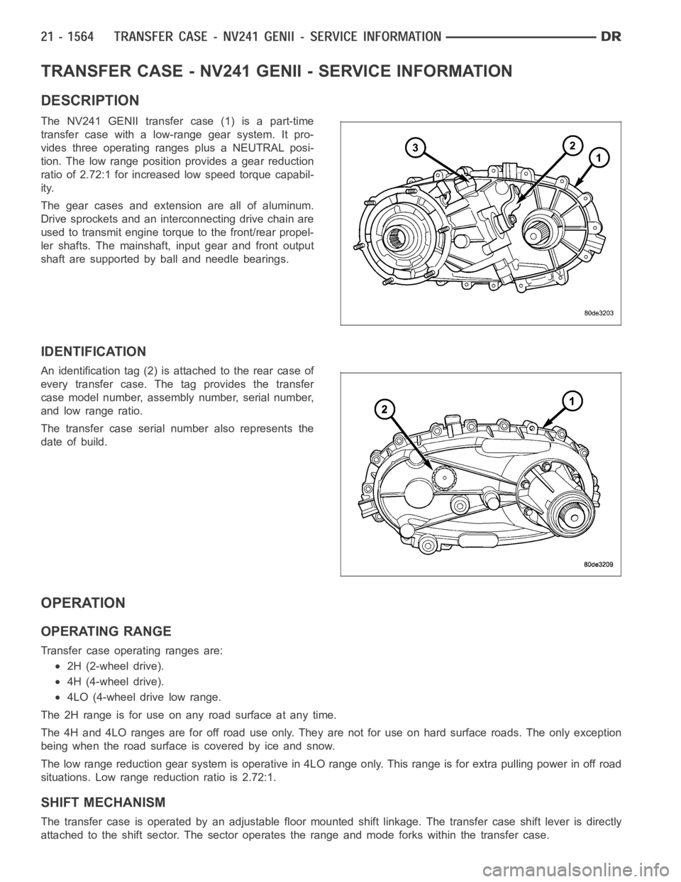
DESCRIPTION
The NV241 GENII transfer case (1) is a part-time
transfer case with a low-range gear system. It pro-
vides three operating ranges plus a NEUTRAL posi-
tion. The low range position provides a gear reduction
ratio of 2.72:1 for increased low speed torque capabil-
ity.
The gear cases and extension are all of aluminum.
Drive sprockets and an interconnecting drive chain are
used to transmit engine torque to the front/rear propel-
ler shafts. The mainshaft, input gear and front output
shaft are supported by ball and needle bearings.
IDENTIFICATION
An identification tag (2) is attached to the rear case of
every transfer case. The tag provides the transfer
case model number, assembly number, serial number,
and low range ratio.
The transfer case serial number also represents the
date of build.
OPERATION
OPERATING RANGE
Transfer case operating ranges are:
2H (2-wheel drive).
4H (4-wheel drive).
4LO (4-wheel drive low range.
The 2H range is for use on any road surface at any time.
The 4H and 4LO ranges are for off road use only. They are not for use on hard surface roads. The only exception
being when the road surface is covered by ice and snow.
The low range reduction gear system is operative in 4LO range only. This range is for extra pulling power in off road
situations. Low range reduction ratio is 2.72:1.
SHIFT MECHANISM
The transfer case is operated by an adjustable floor mounted shift linkage. The transfer case shift lever is directly
attached to the shift sector. The sector operates the range and mode forks within the transfer case.
Page 4086 of 5267
A straight line shift pattern is used with a NEUTRAL detent. Lever range positions are imprinted in the shift knob.
SHIFTING
The transfer case can be shifted between the 2H and 4H operating ranges while the vehicle is in motion. The vehi-
cle must have the transmission placed in NEUTRAL, or the clutch depressed in the case of a manual transmission,
and be moving less than 2-3 MPH when shifting into and out of the 4L operatingrange.
DIAGNOSIS AND TESTING - TRANSFER CASE - NV241 GENII
Before beginning repair on a suspected transfer case malfunction, check all other driveline components beforehand.
The actual cause of a problem may be related to such items as: front hubs, axles, propeller shafts, wheels and tires,
transmission, or clutch instead. If all other driveline components are ingood condition and operating properly, refer
to the Diagnosis Chart for further information.
DIAGNOSIS CHART
Condition Possible Cause Correction
Transfer Case difficult to shift or will
not shift into desired range.1) Vehicle speed too great to permit
shifting.1) Stop vehicle and shift into
desired range. Or, reduce speed to
below 3-4 km/h (2-3 mph) before
attempting the shift.
2) If vehicle was operated for an
extended period in 4H on a dry
paved surface, the driveline torque
load may be causing a bind.2) Stop vehicle and shift the
transmission into neutral. Shift the
transfer case to 2H and operate
vehicle in 2H on dry paved
surfaces.
3) Transfer case external shift
linkage binding.3) Lubricate, repair, or replace
linkage bushings, or tighten loose
components as necessary.
4) Insufficient or incorrect lubricant. 4) Drain and refill to edge of fillhole
with Mopar
ATF +4, Automatic
Transmission fluid.
5) Internal components binding,
worn, or damaged.5) Disassemble the transfer case
and replace worn or damaged
components as necessary.
Transfer Case noisy in all operating
ranges.1) Insufficient or incorrect lubricant. 1) Drain and refill to edge of fillhole
with Mopar
ATF +4, Automatic
Transmission fluid.
Noisy in, or jumps out of, four wheel
drive low range.1) Transfer case not completely
engaged in 4L position.1) With the transmission in
NEUTRAL, or the clutch depressed
in the case of a manual
transmission and the vehicle moving
under 3-4 km/h (2-3 mph), shift the
transfer case to NEUTRAL and then
shift into the 4L position.
2) Shift linkage out of adjustment. 2) Adjust linkage.
3) Shift linkage loose or binding. 3) Tighten, lubricate, or repair
linkage as necessary.
4) Range fork damaged, inserts
worn, or fork is binding on the shift
rail.4) Disassemble unit and repair as
necessary.
5) Low range gear worn or
damaged.5) Disassemble unit and repair as
necessary.
Page 4127 of 5267
TRANSFER CASE - NV271 - SERVICE INFORMATION
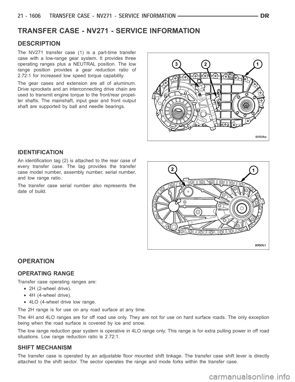
DESCRIPTION
The NV271 transfer case (1) is a part-time transfer
case with a low-range gear system. It provides three
operating ranges plus a NEUTRAL position. The low
range position provides a gear reduction ratio of
2.72:1 for increased low speed torque capability.
The gear cases and extension are all of aluminum.
Drive sprockets and an interconnecting drive chain are
used to transmit engine torque to the front/rear propel-
ler shafts. The mainshaft, input gear and front output
shaft are supported by ball and needle bearings.
IDENTIFICATION
An identification tag (2) is attached to the rear case of
every transfer case. The tag provides the transfer
case model number, assembly number, serial number,
and low range ratio.
The transfer case serial number also represents the
date of build.
OPERATION
OPERATING RANGE
Transfer case operating ranges are:
2H (2-wheel drive).
4H (4-wheel drive).
4LO (4-wheel drive low range.
The 2H range is for use on any road surface at any time.
The 4H and 4LO ranges are for off road use only. They are not for use on hard surface roads. The only exception
being when the road surface is covered by ice and snow.
The low range reduction gear system is operative in 4LO range only. This range is for extra pulling power in off road
situations. Low range reduction ratio is 2.72:1.
SHIFT MECHANISM
The transfer case is operated by an adjustable floor mounted shift linkage. The transfer case shift lever is directly
attached to the shift sector. The sector operates the range and mode forks within the transfer case.