2006 DODGE RAM SRT-10 wheel
[x] Cancel search: wheelPage 2479 of 5267
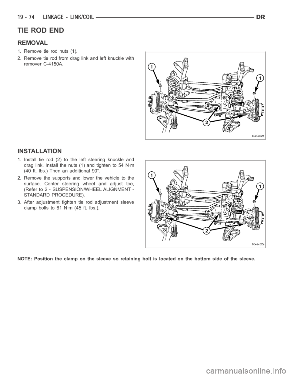
TIE ROD END
REMOVAL
1. Remove tie rod nuts (1).
2. Remove tie rod from drag link and left knuckle with
remover C-4150A.
INSTALLATION
1. Install tie rod (2) to the left steering knuckle and
drag link. Install the nuts (1) and tighten to 54 Nꞏm
(40 ft. lbs.) Then an additional 90°.
2. Remove the supports and lower the vehicle to the
surface. Center steering wheel and adjust toe,
(Refer to 2 - SUSPENSION/WHEEL ALIGNMENT -
STANDARD PROCEDURE).
3. After adjustment tighten tie rod adjustment sleeve
clamp bolts to 61 Nꞏm (45 ft. lbs.).
NOTE: Position the clamp on the sleeve so retaining bolt is located on the bottom side of the sleeve.
Page 2483 of 5267
1. Raise the front end of the vehicle off the ground until the wheels are freeto turn.
2. Remove the return line from the pump.
NOTE: If vehicle is equipped with a hydraulic booster remove both return lines from the pump.
3. Plug the return line port/ports at the pump.
4. Position the return line/lines into a large container to catch the fluid.
5. While an assistant is filling the pump reservoir start the engine.
6. With the engine running at idle turn the wheel back and forth.
NOTE: Do not contact or hold the wheel against the steering stops.
7. Run a quart of fluid through the system then stop the engine and install the return line/lines.
8. Fill the system with fluid and perform Steering Pump Initial Operation,(Refer to 19 - STEERING/PUMP - STAN-
DARD PROCEDURE).
9. Start the engine and run it for fifteen minutes then stop the engine.
10. Remove the return line/lines from the pump and plug the pump port/ports.
11. Pour fresh fluid into the reservoir and check the draining fluid for contamination. If the fluid is still contaminated,
then flush the system again.
12. Install the return line/lines and perform Steering Pump Initial Operation, (Refer to 19 - STEERING/PUMP -
STANDARD PROCEDURE).
POWER STEERING PUMP - INITIAL OPERATION
WARNING: THE FLUID LEVEL SHOULD BE CHECKED WITH ENGINE OFF TO PREVENT INJURYFROMMOV-
ING COMPONENTS.
CAUTION: MOPAR
ATF+4 is to be used in the power steering system. No other power steering or auto-
matic transmission fluid is to be used in the system. Damage may result to the power steering pump and
system if any other fluid is used, and do not overfill.
Wipe filler cap clean, then check the fluid level. The dipstick should indicateCOLDwhen the fluid is at normal
temperature.
1. Turn steering wheel all the way to the left.
2. Fill reservoir up to FULL HOT level and crank engine until it just starts.(DO NOT TURN STEERING WHEEL).
Then turn vehicle off. And recheck fluid level, to Full COLD.
3. Crank engine again until it just starts, (DO NOT MOVE STEERING WHEEL). and turn vehicle off. Recheck fluid
leveltoFullCOLD.
4. Turn engine on again, (DO NOT MOVE STEERING WHEEL) and let the vehicle idle for 5 minutes. If possible
apply a 20 in-Hg vacuum to the reservoir, while engine is idling.
5. Turn engine off and recheck fluid level, to FULL COLD.
6.If the Steering gear is replacedensure reservoir is at FULL HOT level, start engine and turn wheel to left. Stop
Engine and recheck fluid level to FULL HOT. Start engine and turn wheel to the right. Stop engine and check
fluid level is at FULL COLD.
7. Fill the pump fluid reservoir to the proper level and let the fluid settlefor at least two (2) minutes.
8. Start the engine. With the engine idling maintain the fluid level.
9. Raise the front wheels off the ground.
10. Slowly turn the steering wheel lock-to-lock 20 times with the engine off while checking the fluid level.
NOTE: For vehicles with long return lines or oil coolers turn wheel 40 times.
11. Lower the front wheels and let the engine idle for two minutes.
12. Turn the steering wheel in both direction and verify power assist and quiet operation of the pump.
If the fluid is extremely foamy or milky looking, allow the vehicle to standa few minutes and repeat the procedure.
Page 2499 of 5267
FLOW AND PRESSURE TEST - AT POWER STEERING GEAR
NOTE: This test should only be done if necessary
after completing the Pump Flow And Pressure Test
1. Remove Analyzer from pump and pressure hose to
fan. Reattach pressure hose to pump.
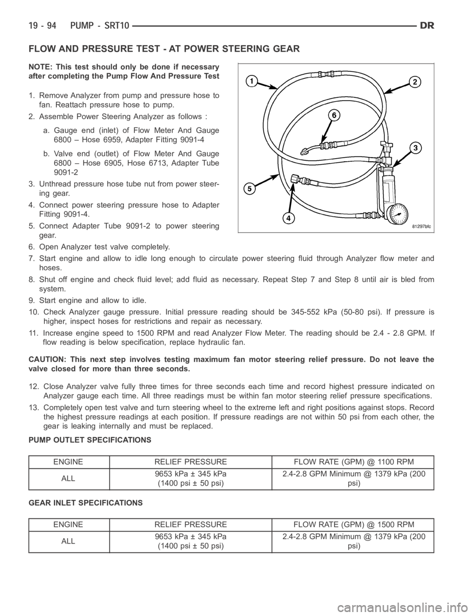
2. Assemble Power Steering Analyzer as follows :
a. Gauge end (inlet) of Flow Meter And Gauge
6800 – Hose 6959, Adapter Fitting 9091-4
b. Valve end (outlet) of Flow Meter And Gauge
6800 – Hose 6905, Hose 6713, Adapter Tube
9091-2
3. Unthread pressure hose tube nut from power steer-
ing gear.
4. Connect power steering pressure hose to Adapter
Fitting 9091-4.
5. Connect Adapter Tube 9091-2 to power steering
gear.
6. Open Analyzer test valve completely.
7. Start engine and allow to idle long enough to circulate power steering fluid through Analyzer flow meter and
hoses.
8. Shut off engine and check fluid level; add fluid as necessary. Repeat Step7andStep8untilairisbledfrom
system.
9. Start engine and allow to idle.
10. Check Analyzer gauge pressure. Initial pressure reading should be 345-552 kPa (50-80 psi). If pressure is
higher, inspect hoses for restrictions and repair as necessary.
11. Increase engine speed to 1500 RPM and read Analyzer Flow Meter. The reading should be 2.4 - 2.8 GPM. If
flow reading is below specification, replace hydraulic fan.
CAUTION: This next step involves testing maximum fan motor steering relief pressure. Do not leave the
valve closed for more than three seconds.
12. Close Analyzer valve fully three times for three seconds each time and record highest pressure indicated on
Analyzer gauge each time. All three readings must be within fan motor steering relief pressure specifications.
13. Completely open test valve and turn steering wheel to the extreme left and right positions against stops. Record
the highest pressure readings at each position. If pressure readings are not within 50 psi from each other, the
gear is leaking internally and must be replaced.
PUMP OUTLET SPECIFICATIONS
ENGINE RELIEF PRESSURE FLOW RATE (GPM) @ 1100 RPM
ALL9653 kPa ± 345 kPa
(1400 psi ± 50 psi)2.4-2.8 GPM Minimum @ 1379 kPa (200
psi)
GEAR INLET SPECIFICATIONS
ENGINE RELIEF PRESSURE FLOW RATE (GPM) @ 1500 RPM
ALL9653 kPa ± 345 kPa
(1400 psi ± 50 psi)2.4-2.8 GPM Minimum @ 1379 kPa (200
psi)
Page 2500 of 5267
STANDARD PROCEDURE
INITIAL OPERATION
WARNING: The fluid level should be checked with engine off to prevent injury from moving components.
NOTE: Remove as much of the old fluid out of the system as possible with a suction tool or by removing
a hose, when a component has failed. Then refill it with fresh fluid until itis clean. This may have to be
done more than once.
CAUTION: MOPAR
ATF+4 is to be used in the power steering system. No other power steering or auto-
matic transmission fluid is to be used in the system. Damage may result to the power steering pump and
system if any other fluid is used, and do not overfill.
Wipe filler cap clean, then check the fluid level. The dipstick should indicateCOLDwhen the fluid is at normal
ambient temperature.
1. Fill the pump fluid reservoir to the proper level and let the fluid settlefor at least two minutes.
2. Start the engine and let run for a few seconds then turn engine off.
3. Add fluid if necessary. Repeat the above procedure until the fluid levelremains constant after running the engine.
4. Raise the front wheels off the ground.
5. Slowly turn the steering wheel right and left, lightly contacting the wheel stops at least 20 times.
6. Check the fluid level add if necessary.
7. Lower the vehicle, start the engine, and use the DRB III to activate the hydraulic fan on full fan operation.
8. Turn the steering wheel slowly from lock to lock.
9. Stop the engine, check the fluid level and refill as required and repeat the process
CAUTION: Do not run a vehicle with foamy fluid for an extended period. This may cause pump damage.
10. If the fluid is extremely foamy or milky looking, allow the vehicle to stand a few minutes and repeat the pro-
cedure.
11. While the vehicle is in park, use the DRB III to activate the hydraulic fan to full fan operation and briefly rev the
engine up to 3000 rpm to fully engage the hydraulic fan.
12. Check the fluid level add if necessary.
Page 2713 of 5267
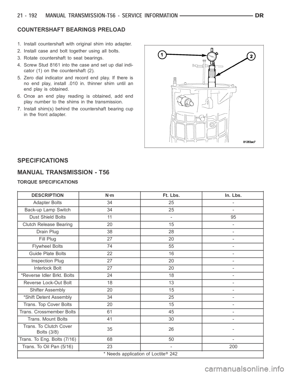
COUNTERSHAFT BEARINGS PRELOAD
1. Install countershaft with original shim into adapter.
2. Install case and bolt together using all bolts.
3. Rotate countershaft to seat bearings.
4. Screw Stud 8161 into the case and set up dial indi-
cator (1) on the countershaft (2).
5. Zero dial indicator and record end play. If there is
no end play, install .010 in. thinner shim until an
end play is obtained.
6. Once an end play reading is obtained, add end
play number to the shims in the transmission.
7. Install shim(s) behind the countershaft bearing cup
in the front adapter.
SPECIFICATIONS
MANUAL TRANSMISSION - T56
TORQUE SPECIFICATIONS
DESCRIPTION Nꞏm Ft. Lbs. In. Lbs.
Adapter Bolts 34 25 -
Back-up Lamp Switch 34 25 -
Dust Shield Bolts 11 - 95
Clutch Release Bearing 20 15 -
Drain Plug 38 28 -
Fill Plug 27 20 -
Flywheel Bolts 74 55 -
Guide Plate Bolts 22 16 -
Inspection Plug 27 20 -
Interlock Bolt 27 20 -
*Reverse Idler Brkt. Bolts 24 18 -
Reverse Lock-Out Bolt 18 13 -
Shifter Assembly 20 15 -
*Shift Detent Assembly 34 25 -
Trans. Top Cover Bolts 20 15 -
Trans. Crossmember Bolts 61 45 -
Trans. Mount Bolts 41 30 -
Trans. To Clutch Cover
Bolts (3/8)35 26 -
Trans. To Eng. Bolts (7/16) 68 50 -
Trans. To Oil Pan (5/16) 23 - 200
* Needs application of Loctite
242
Page 2765 of 5267
When Monitored:
The transmission gear ratio is monitored continuously while the transmission is in gear.
Set Condition:
If there is an excessive change in the Output RPM in any gear.
Possible Causes
(T14) OUTPUT SPEED SENSOR SIGNAL CIRCUIT OPEN
(T13) SPEED SENSOR GROUND CIRCUIT OPEN
(T14) OUTPUT SPEED SENSOR SIGNAL CIRCUIT SHORT TO GROUND
(T14) OUTPUT SPEED SENSOR SIGNAL CIRCUIT SHORT TO VOLTAGE
(T13) SPEED SENSOR GROUND CIRCUIT SHORT TO VOLTAGE
OUTPUT SPEED SENSOR
POWERTRAIN CONTROL MODULE
Always perform the Pre-Diagnostic Troubleshooting procedure before proceeding. (Refer to 21 - TRANSMIS-
SION/TRANSAXLE/AUTOMATIC - 42RLE - STANDARD PROCEDURE)
Theory of Operation
The transmission system uses two speed sensors, one to measure input RPM and one to measure output RPM.
These inputs are essential for proper transmission operation. Therefore, the integrity of this data is verified through
system checks.
Diagnostic Test
1.CHECK IF THE DTC IS CURRENT
Start the engine in park.
Raise the drive wheels off of the ground.
WARNING: Properly support the vehicle.
Firmly apply the brakes and place the transmission selector in drive.
WARNING: Be sure to keep hands and feet clear of rotating wheels.
Release the brakes and allow the drive wheels to spin freely.
NOTE: The drive wheels must be turning at this point.
With the scan tool, read the Output RPM
Is the Output RPM below 100?
Ye s>>
Go To 2
No>>
Go To 8
2.CHECK THE PCM AND WIRING USING THE TRANSMISSION SIMULATOR
Turn the ignition off to the lock position.
Remove the Ignition Switch Feed fuse from the TIPM.
CAUTION: Removal of the Ignition Switch Feed fuse from the TIPM will prevent the vehicle from being
startedingear.
WARNING: The Ignition Switch Feed fuse must be removed from the TIPM. Failure to do so can result in
personal injury or death.
Install the Transmission Simulator,Miller tool #8333 and the ElectronicTransmission Adapter kit.
Ignition on, engine not running.
With the Transmission Simulator, set the
Input/Output Speedswitch toONand the rotary switch to the3000/
1250
position.
Page 2915 of 5267
First 2.84 : 1
Second 1.57 : 1
Third 1.00 : 1
Overdrive 0.69 : 1
Reverse 2.21 : 1
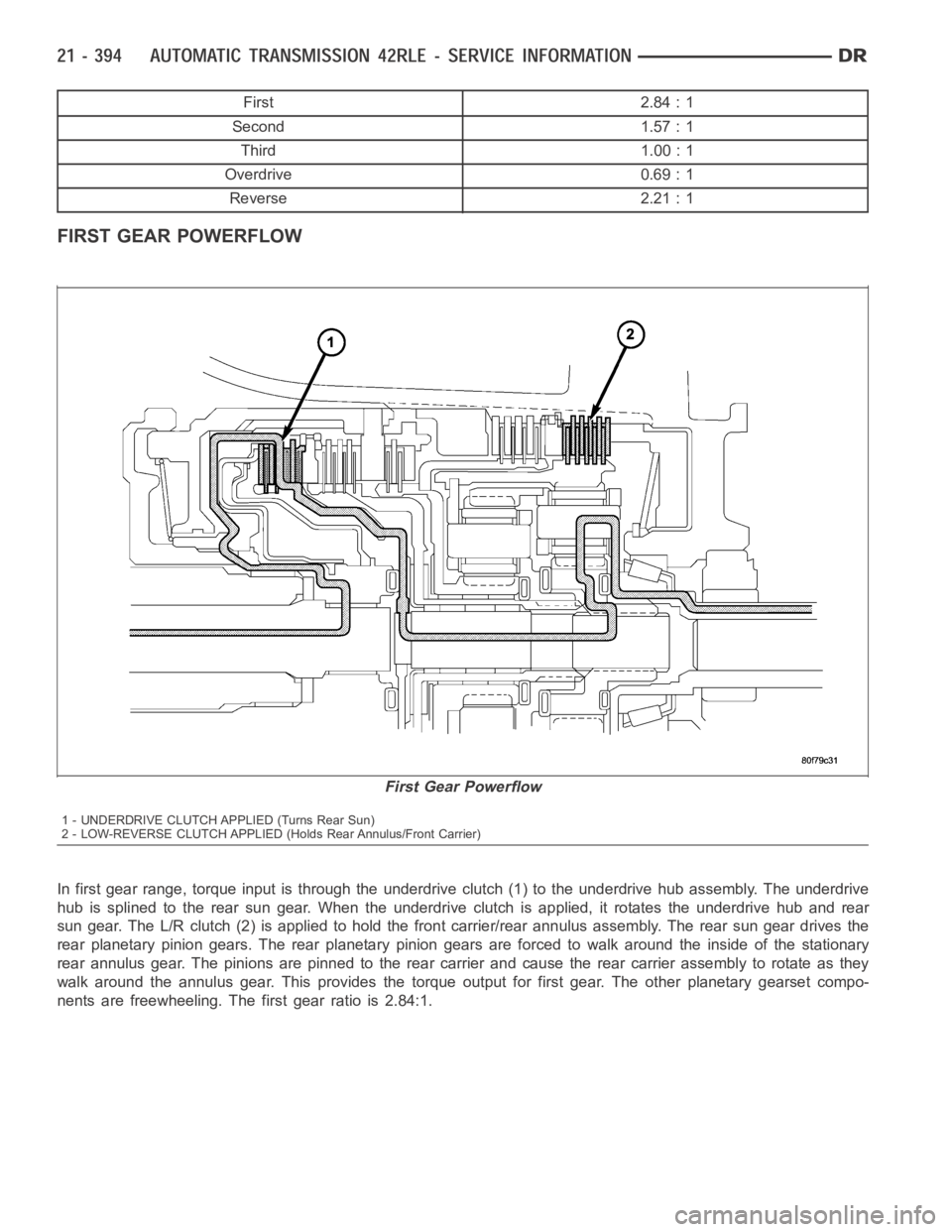
FIRST GEAR POWERFLOW
In first gear range, torque input is through the underdrive clutch (1) to the underdrive hub assembly. The underdrive
hub is splined to the rear sun gear. When the underdrive clutch is applied, it rotates the underdrive hub and rear
sun gear. The L/R clutch (2) is applied to hold the front carrier/rear annulus assembly. The rear sun gear drives the
rear planetary pinion gears. The rear planetary pinion gears are forced towalk around the inside of the stationary
rear annulus gear. The pinions are pinned to the rear carrier and cause the rear carrier assembly to rotate as they
walk around the annulus gear. This provides the torque output for first gear. The other planetary gearset compo-
nents are freewheeling. The first gear ratio is 2.84:1.
First Gear Powerflow
1 - UNDERDRIVE CLUTCH APPLIED (Turns Rear Sun)
2 - LOW-REVERSE CLUTCH APPLIED (Holds Rear Annulus/Front Carrier)
Page 2921 of 5267
HYDRAULIC PRESSURE TESTS
Pressure testing is a very important step in the diag-
nostic procedure. These tests usually reveal the cause
of most transmission problems.
Before performing pressure tests, be certain that fluid
level and condition, and shift cable adjustments have
been checked and approved. Fluid must be at operat-
ing temperature (150 to 200 degrees F.).
Install an engine tachometer, raise vehicle on hoist
which allows the wheels to turn, and position tachom-
eter so it can be read.
Using special adapters L-4559, attach 300 psi
gauge(s) C-3293SP to the port(s) required for test
being conducted.
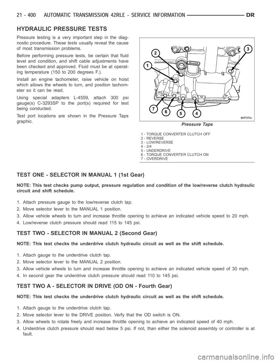
Test port locations are shown in the Pressure Taps
graphic.
TEST ONE - SELECTOR IN MANUAL 1 (1st Gear)
NOTE: This test checks pump output, pressure regulation and condition of the low/reverse clutch hydraulic
circuit and shift schedule.
1. Attach pressure gauge to the low/reverse clutch tap.
2. Move selector lever to the MANUAL 1 position.
3. Allow vehicle wheels to turn and increase throttle opening to achieve anindicatedvehiclespeedto20mph.
4. Low/reverse clutch pressure should read 115 to 145 psi.
TEST TWO - SELECTOR IN MANUAL 2 (Second Gear)
NOTE: This test checks the underdrive clutch hydraulic circuit as well as the shift schedule.
1. Attach gauge to the underdrive clutch tap.
2. Move selector lever to the MANUAL 2 position.
3. Allow vehicle wheels to turn and increase throttle opening to achieve anindicated vehicle speed of 30 mph.
4. In second gear the underdrive clutch pressure should read 110 to 145 psi.
TEST TWO A - SELECTOR IN DRIVE (OD ON - Fourth Gear)
NOTE: This test checks the underdrive clutch hydraulic circuit as well as the shift schedule.
1. Attach gauge to the underdrive clutch tap.
2. Move selector lever to the DRIVE position. Verfy that the OD switch is ON.
3. Allow wheels to rotate freely and increase throttle opening to achieve an indicated speed of 40 mph.
4. Underdrive clutch pressure should read below 5 psi. If not, than either the solenoid assembly or controller is at
fault.
Pressure Taps
1 - TORQUE CONVERTER CLUTCH OFF
2 - REVERSE
3 - LOW/REVERSE
4-2/4
5 - UNDERDRIVE
6 - TORQUE CONVERTER CLUTCH ON
7-OVERDRIVE