2006 DODGE RAM SRT-10 wheel
[x] Cancel search: wheelPage 3367 of 5267
Improper adjustments
Hydraulic malfunctions
Mechanical malfunctions
Electronic malfunctions
Diagnosis of these problems should always begin by checking the easily accessible variables: fluid level and con-
dition, gearshift cable adjustment. Then perform a road test to determineif the problem has been corrected or if
more diagnosis is necessary. If the problem persists after the preliminary tests and corrections are completed,
hydraulic pressure checks should be performed.
PRELIMINARY
Two basic procedures are required. One procedure for vehicles that are drivable and an alternate procedure for
disabled vehicles (will not back up or move forward).
VEHICLE IS DRIVABLE
1. Check for transmission fault codes using scan tool.
2. Check fluid level and condition.
3. Adjust gearshift cable if complaint was based on delayed, erratic, or harsh shifts.
4. Road test and note how transmission upshifts, downshifts, and engages.
5. Perform hydraulic pressure test if shift problems were noted during roadtest.
6. Perform air-pressure test to check clutch operation.
VEHICLE IS DISABLED
1. Check fluid level and condition.
2. Check for broken or disconnected gearshift cable.
3. Check for cracked, leaking cooler lines, or loose or missing pressure-port plugs.
4. Raise and support vehicle on safety stands, start engine, shift transmission into gear, and note following:
a. If propeller shaft turns but wheels do not, problem is with differentialor axle shafts.
b. If propeller shaft does not turn and transmission is noisy, stop engine.Remove oil pan, and check for debris.
If pan is clear, remove transmission and check for damaged driveplate, converter, oil pump, or input shaft.
c. If propeller shaft does not turn and transmission is not noisy, perform hydraulic-pressure test to determine if
problem is hydraulic or mechanical.
ROAD TESTING
Before road testing, be sure the fluid level and control cable adjustmentshave been checked and adjusted if nec-
essary. Verify that all diagnostic trouble codes have been resolved.
Observe engine performance during the road test. A poorly tuned engine will not allow accurate analysis of trans-
mission operation.
Operate the transmission in all gear ranges. Check for shift variations and engine flare which indicates slippage.
Note if shifts are harsh, spongy, delayed, early, or if part throttle downshifts are sensitive.
Slippage indicated by engine flare, usually means clutch, overrunning clutch, or line pressure problems.
A slipping clutch can often be determined by comparing which internal units are applied in the various gear ranges.
The Clutch Application charts provide a basis for analyzing road test results.
45RFE CLUTCH APPLICATION CHART
Page 3389 of 5267
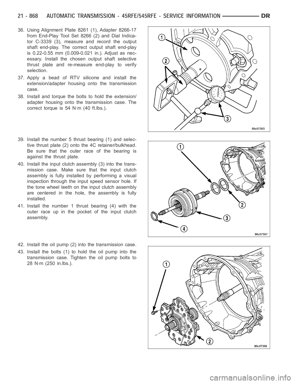
36. Using Alignment Plate 8261 (1), Adapter 8266-17
from End-Play Tool Set 8266 (2) and Dial Indica-
tor C-3339 (3), measure and record the output
shaft end-play. The correct output shaft end-play
is 0.22-0.55 mm (0.009-0.021 in.). Adjust as nec-
essary. Install the chosen output shaft selective
thrust plate and re-measure end-play to verify
selection.
37. Apply a bead of RTV silicone and install the
extension/adapter housing onto the transmission
case.
38. Install and torque the bolts to hold the extension/
adapter housing onto the transmission case. The
correct torque is 54 Nꞏm (40 ft.lbs.).
39. Install the number 5 thrust bearing (1) and selec-
tive thrust plate (2) onto the 4C retainer/bulkhead.
Be sure that the outer race of the bearing is
against the thrust plate.
40. Install the input clutch assembly (3) into the trans-
mission case. Make sure that the input clutch
assembly is fully installedbyperformingavisual
inspection through the input speed sensor hole. If
the tone wheel teeth on the input clutch assembly
are centered in the hole, the assembly is fully
installed.
41. Install the number 1 thrust bearing (4) with the
outer race up in the pocket of the input clutch
assembly.
42. Install the oil pump (2) into the transmission case.
43. Install the bolts (1) to hold the oil pump into the
transmission case. Tighten the oil pump bolts to
28 Nꞏm (250 in.lbs.).
Page 3486 of 5267
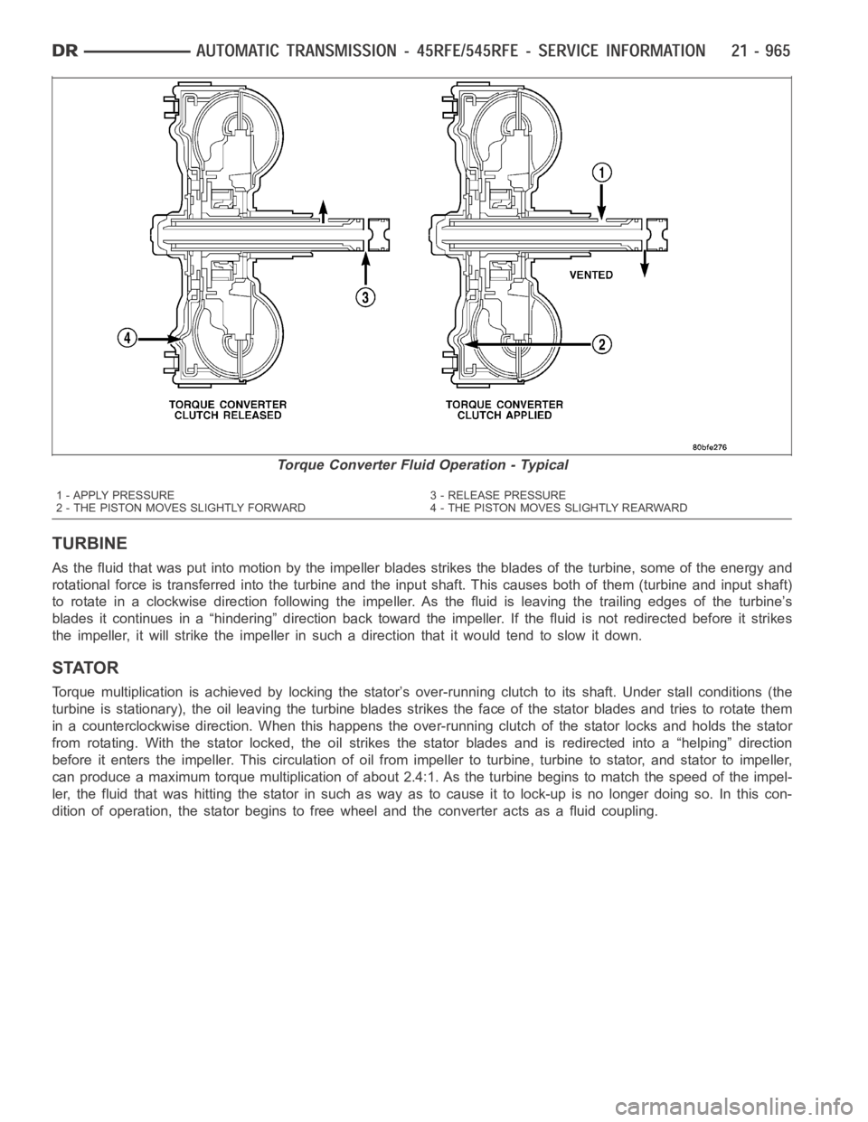
TURBINE
As the fluid that was put into motion bythe impeller blades strikes the blades of the turbine, some of the energy and
rotational force is transferred into the turbine and the input shaft. Thiscauses both of them (turbine and input shaft)
to rotate in a clockwise direction following the impeller. As the fluid is leaving the trailing edges of the turbine’s
blades it continues in a “hindering” direction back toward the impeller. If the fluid is not redirected before it strikes
the impeller, it will strike the impeller in such a direction that it would tend to slow it down.
STATOR
Torque multiplication is achieved by locking the stator’s over-running clutch to its shaft. Under stall conditions (the
turbine is stationary), the oil leaving the turbine blades strikes the face of the stator blades and tries to rotate them
in a counterclockwise direction. When this happens the over-running clutch of the stator locks and holds the stator
from rotating. With the stator locked, the oil strikes the stator blades and is redirected into a “helping” direction
before it enters the impeller. This circulation of oil from impeller to turbine, turbine to stator, and stator to impeller,
can produce a maximum torque multiplicationofabout2.4:1.Astheturbinebegins to match the speed of the impel-
ler, the fluid that was hitting the stator in such as way as to cause it to lock-up is no longer doing so. In this con-
dition of operation, the stator begins to free wheel and the converter actsas a fluid coupling.
Torque Converter Fluid Operation - Typical
1 - APPLY PRESSURE 3 - RELEASE PRESSURE
2 - THE PISTON MOVES SLIGHTLY FORWARD 4 - THE PISTON MOVES SLIGHTLY REARWARD
Page 3487 of 5267
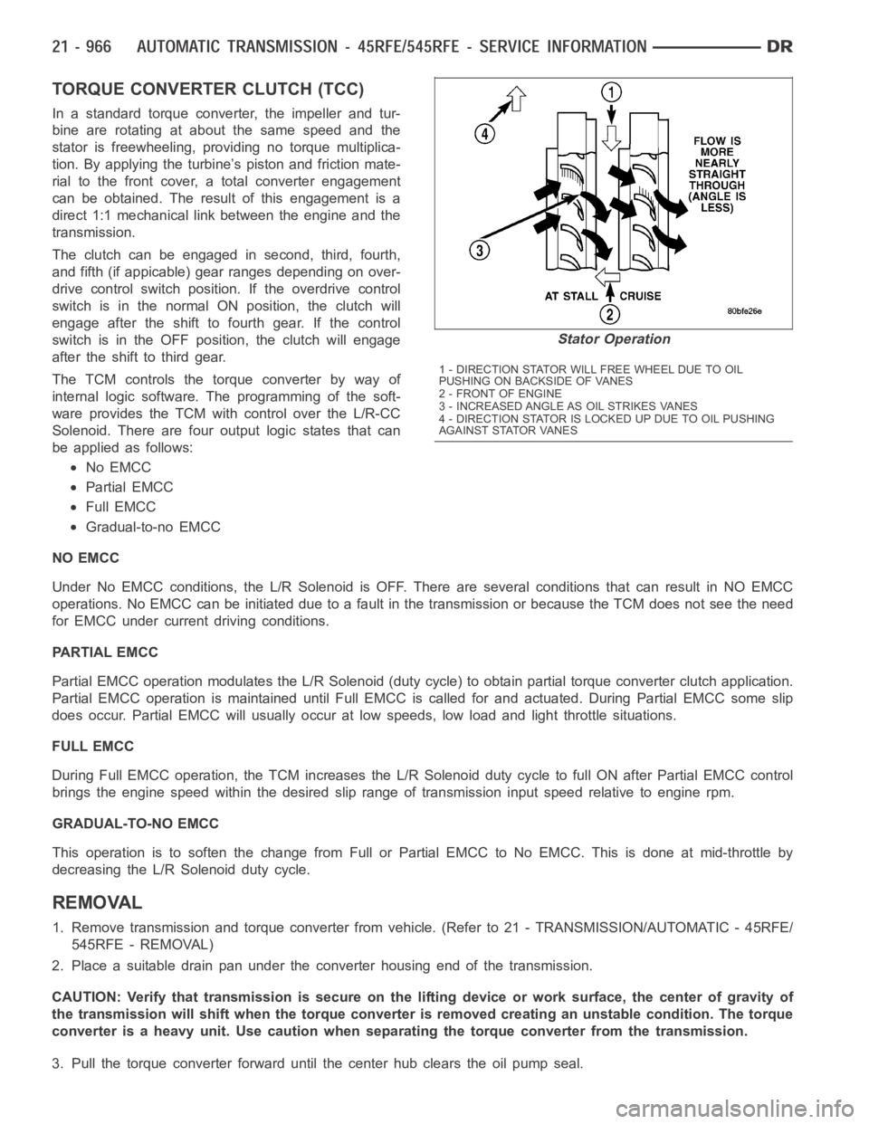
TORQUE CONVERTER CLUTCH (TCC)
In a standard torque converter, the impeller and tur-
bine are rotating at about the same speed and the
stator is freewheeling, providing no torque multiplica-
tion. By applying the turbine’s piston and friction mate-
rial to the front cover, a total converter engagement
can be obtained. The result of this engagement is a
direct 1:1 mechanical link between the engine and the
transmission.
The clutch can be engaged in second, third, fourth,
and fifth (if appicable) gear ranges depending on over-
drive control switch position. If the overdrive control
switch is in the normal ON position, the clutch will
engage after the shift to fourth gear. If the control
switch is in the OFF position, the clutch will engage
after the shift to third gear.
The TCM controls the torque converter by way of
internal logic software. The programming of the soft-
ware provides the TCM with control over the L/R-CC
Solenoid. There are four output logic states that can
be applied as follows:
No EMCC
Partial EMCC
Full EMCC
Gradual-to-no EMCC
NO EMCC
Under No EMCC conditions, the L/R Solenoid is OFF. There are several conditions that can result in NO EMCC
operations. No EMCC can be initiated due to a fault in the transmission or because the TCM does not see the need
for EMCC under current driving conditions.
PARTIAL EMCC
Partial EMCC operation modulates the L/R Solenoid (duty cycle) to obtain partial torque converter clutch application.
Partial EMCC operation is maintaineduntil Full EMCC is called for and actuated. During Partial EMCC some slip
does occur. Partial EMCC will usually occur at low speeds, low load and light throttle situations.
FULL EMCC
During Full EMCC operation, the TCM increases the L/R Solenoid duty cycle to full ON after Partial EMCC control
brings the engine speed within the desired slip range of transmission input speed relative to engine rpm.
GRADUAL-TO-NO EMCC
This operation is to soften the change from Full or Partial EMCC to No EMCC. This is done at mid-throttle by
decreasing the L/R Solenoid duty cycle.
REMOVAL
1. Remove transmission and torque converter from vehicle. (Refer to 21 - TRANSMISSION/AUTOMATIC - 45RFE/
545RFE - REMOVAL)
2. Place a suitable drain pan under the converter housing end of the transmission.
CAUTION: Verify that transmission is secure on the lifting device or work surface, the center of gravity of
the transmission will shift when the torque converter is removed creatingan unstable condition. The torque
converter is a heavy unit. Use caution when separating the torque converter from the transmission.
3. Pull the torque converter forward until the center hub clears the oil pumpseal.
Stator Operation
1 - DIRECTION STATOR WILL FREE WHEEL DUE TO OIL
PUSHING ON BACKSIDE OF VANES
2-FRONTOFENGINE
3 - INCREASED ANGLE AS OIL STRIKES VANES
4 - DIRECTION STATOR IS LOCKED UP DUE TO OIL PUSHING
AGAINST STATOR VANES
Page 3796 of 5267
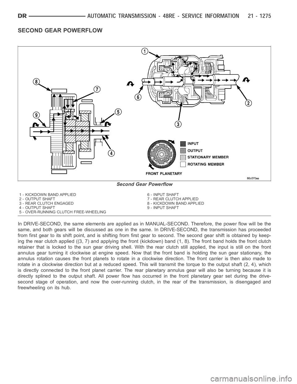
SECOND GEAR POWERFLOW
In DRIVE-SECOND, the same elements are applied as in MANUAL-SECOND. Therefore, the power flow will be the
same, and both gears will be discussed as one in the same. In DRIVE-SECOND, the transmission has proceeded
from first gear to its shift point, and is shifting from first gear to second. The second gear shift is obtained by keep-
ing the rear clutch applied ((3, 7) and applying the front (kickdown) band (1, 8). The front band holds the front clutch
retainer that is locked to the sun gear driving shell. With the rear clutch still applied, the input is still on the front
annulus gear turning it clockwise at engine speed. Now that the front band is holding the sun gear stationary, the
annulus rotation causes the front planets to rotate in a clockwise direction. The front carrier is then also made to
rotate in a clockwise direction but at a reduced speed. This will transmit the torque to the output shaft (2, 4), which
is directly connected to the front planet carrier. The rear planetary annulus gear will also be turning because it is
directly splined to the output shaft. All power flow has occurred in the front planetary gear set during the drive-
second stage of operation, and now the over-running clutch, in the rear of the transmission, is disengaged and
freewheeling on its hub.
Second Gear Powerflow
1 - KICKDOWN BAND APPLIED 6 - INPUT SHAFT
2 - OUTPUT SHAFT 7 - REAR CLUTCH APPLIED
3 - REAR CLUTCH ENGAGED 8 - KICKDOWN BAND APPLIED
4 - OUTPUT SHAFT 9 - INPUT SHAFT
5 - OVER-RUNNING CLUTCH FREE-WHEELING
Page 3797 of 5267
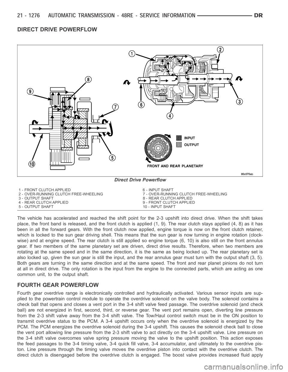
DIRECT DRIVE POWERFLOW
The vehicle has accelerated and reached the shift point for the 2-3 upshiftinto direct drive. When the shift takes
place, the front band is released, and the front clutch is applied (1, 9). The rear clutch stays applied (4, 8) as it has
been in all the forward gears. With the front clutch now applied, engine torque is now on the front clutch retainer,
which is locked to the sun gear drivingshell. This means that the sun gear isnow turning in engine rotation (clock-
wise) and at engine speed. The rear clutch is still applied so engine torque(6, 10) is also still on the front annulus
gear. If two members of the same planetary set are driven, direct drive results. Therefore, when two members are
rotating at the same speed and in the same direction, it is the same as being locked up. The rear planetary set is
also locked up, given the sun gear is still the input, and the rear annulus gear must turn with the output shaft (3, 5).
Both gears are turning in the same direction and at the same speed. The frontand rear planet pinions do not turn
at all in direct drive. The only rotation is the input from the engine to the connected parts, which are acting as one
common unit, to the output shaft.
FOURTHGEARPOWERFLOW
Fourth gear overdrive range is electronically controlled and hydraulically activated. Various sensor inputs are sup-
plied to the powertrain control module to operate the overdrive solenoid on the valve body. The solenoid contains a
check ball that opens and closes a vent port in the 3-4 shift valve feed passage. The overdrive solenoid (and check
ball) are not energized in first, second, third, or reverse gear. The vent port remains open, diverting line pressure
from the 2-3 shift valve away from the 3-4 shift valve. The Tow/Haul controlswitch must be in the ON position to
transmit overdrive status to the PCM. A 3-4 upshift occurs only when the overdrive solenoid is energized by the
PCM. The PCM energizes the overdrive solenoid during the 3-4 upshift. Thiscauses the solenoid check ball to close
the vent port allowing line pressure from the 2-3 shift valve to act directly on the 3-4 upshift valve. Line pressure on
the 3-4 shift valve overcomes valve spring pressure moving the valve to theupshift position. This action exposes
the feed passages to the 3-4 timing valve, 3-4 quick fill valve, 3-4 accumulator, and ultimately to the overdrive pis-
ton. Line pressure through the timing valve moves the overdrive piston into contact with the overdrive clutch. The
direct clutch is disengaged before the overdrive clutch is engaged. The boost valve provides increased fluid apply
Direct Drive Powerflow
1 - FRONT CLUTCH APPLIED 6 - INPUT SHAFT
2 - OVER-RUNNING CLUTCH FREE-WHEELING 7 - OVER-RUNNING CLUTCH FREE-WHEELING
3 - OUTPUT SHAFT 8 - REAR CLUTCH APPLIED
4 - REAR CLUTCH APPLIED 9 - FRONT CLUTCH APPLIED
5 - OUTPUT SHAFT 10 - INPUT SHAFT
Page 3798 of 5267
pressure to the overdrive clutch during 3-4 upshifts, and when accelerating in fourth gear. The 3-4 accumulator
cushions overdrive clutch engagement to smooth 3-4 upshifts. The accumulator is charged at the same time as
apply pressure acts against the overdrive piston.
DIAGNOSIS AND TESTING
AUTOMATIC TRANSMISSION
Automatic transmission problems can be a result of poor engine performance, incorrect fluid level, incorrect linkage
or cable adjustment, band or hydraulic control pressure adjustments, hydraulic system malfunctions or electrical/
mechanical component malfunctions. Begin diagnosis by checking the easily accessible items such as: fluid level
and condition, linkage adjustments and electrical connections. A road test will determine if further diagnosis is nec-
essary.
PRELIMINARY
Two basic procedures are required. One procedure for vehicles that are drivable and an alternate procedure for
disabled vehicles (will not back up or move forward).
VEHICLE IS DRIVEABLE
1. Check for transmission fault codes using DRBscan tool.
2. Check fluid level and condition.
3. Adjust throttle and gearshift linkage if complaint was based on delayed, erratic, or harsh shifts.
4. Road test and note how transmission upshifts, downshifts, and engages.
5. Perform hydraulic pressure test if shift problems were noted during roadtest.
6. Perform air-pressure test to check clutch-band operation.
VEHICLE IS DISABLED
1. Check fluid level and condition.
2. Check for broken or disconnected gearshift or throttle linkage.
3. Check for cracked, leaking cooler lines, or loose or missing pressure-port plugs.
4. Raise and support vehicle on safety stands, start engine, shift transmission into gear, and note following:
a. If propeller shaft turns but wheels do not, problem is with differentialor axle shafts.
b. If propeller shaft does not turn and transmission is noisy, stop engine.Remove oil pan, and check for debris.
If pan is clear, remove transmission and check for damaged drive plate, converter, oil pump, or input shaft.
c. If propeller shaft does not turn and transmission is not noisy, perform hydraulic-pressure test to determine if
problem is hydraulic or mechanical.
ROAD TESTING
Before road testing, be sure the fluid level and control cable adjustmentshave been checked and adjusted if nec-
essary. Verify that diagnostic trouble codes have been resolved.
Observe engine performance during the road test. A poorly tuned engine will not allow accurate analysis of trans-
mission operation.
Operate the transmission in all gear ranges. Check for shift variations and engine flare which indicates slippage.
Note if shifts are harsh, spongy, delayed, early, or if part throttle downshifts are sensitive.
Slippage indicated by engine flare, usually means clutch, band or overrunning clutch problems. If the condition is
advanced, an overhaul will be necessary to restore normal operation.
A slipping clutch or band can often be determined by comparing which internal units are applied in the various gear
ranges. The Clutch and Band Application chart provides a basis for analyzing road test results.
Clutch and Band Application Chart
Page 3800 of 5267
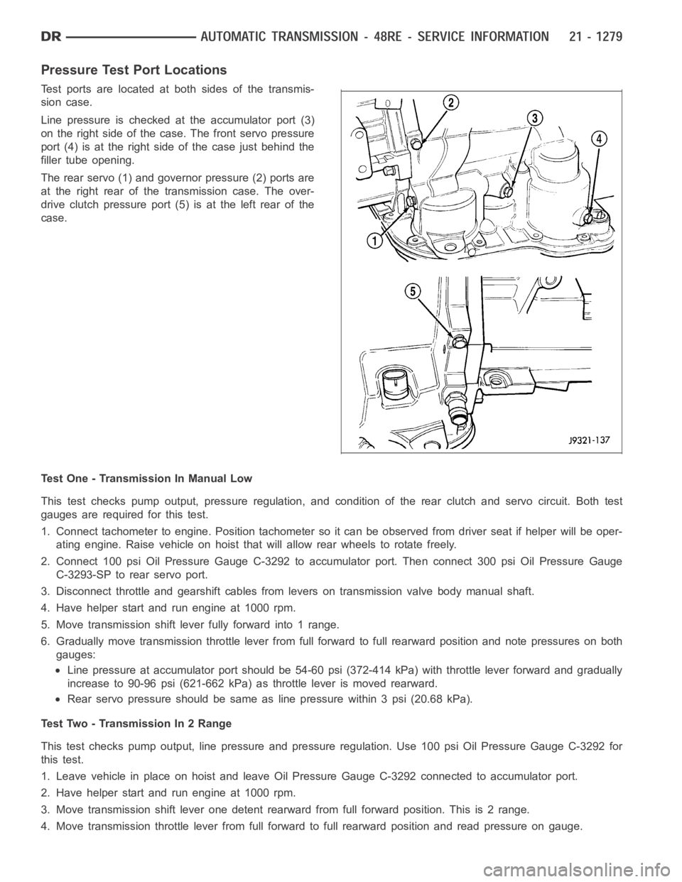
Pressure Test Port Locations
Test ports are located at both sides of the transmis-
sion case.
Line pressure is checked at the accumulator port (3)
on the right side of the case. The front servo pressure
port (4) is at the right side of the case just behind the
filler tube opening.
The rear servo (1) and governor pressure (2) ports are
at the right rear of the transmission case. The over-
drive clutch pressure port (5) is at the left rear of the
case.
Test One - Transmission In Manual Low
This test checks pump output, pressure regulation, and condition of the rear clutch and servo circuit. Both test
gauges are required for this test.
1. Connect tachometer to engine. Position tachometer so it can be observedfrom driver seat if helper will be oper-
ating engine. Raise vehicle on hoist that will allow rear wheels to rotate freely.
2. Connect 100 psi Oil Pressure Gauge C-3292 to accumulator port. Then connect 300 psi Oil Pressure Gauge
C-3293-SP to rear servo port.
3. Disconnect throttle and gearshift cables from levers on transmission valve body manual shaft.
4. Have helper start and run engine at 1000 rpm.
5. Move transmission shift lever fully forward into 1 range.
6. Gradually move transmission throttle lever from full forward to full rearward position and note pressures on both
gauges:
Line pressure at accumulator port should be 54-60 psi (372-414 kPa) with throttle lever forward and gradually
increase to 90-96 psi (621-662 kPa) as throttle lever is moved rearward.
Rear servo pressure should be same asline pressure within 3 psi (20.68 kPa).
Test Two - Transmission In 2 Range
This test checks pump output, line pressure and pressure regulation. Use 100 psi Oil Pressure Gauge C-3292 for
this test.
1. Leave vehicle in place on hoist and leave Oil Pressure Gauge C-3292 connected to accumulator port.
2. Have helper start and run engine at 1000 rpm.
3. Move transmission shift lever one detent rearward from full forward position. This is 2 range.
4. Move transmission throttle lever from full forward to full rearward position and read pressure on gauge.