Page 2217 of 5267
Fig. 10 160.5 IN WHEELBASE - 3500 - 4 WHEEL DRIVE
Page 2242 of 5267

8. Connect other end of jumper wire to positive side of battery.
9. Connect one end of a second jumper wire to remaining injector terminal.
CAUTION: Powering an injector for more than a few seconds will permanentlydamage the injector.
10. Momentarily touch other end of jumper wire to negative terminal of battery for no more than a few seconds.
11. Place a rag or towel below fuel line quick-connect fitting at fuel rail.
12. Disconnect quick-connect fitting at fuel rail. Refer to Quick-Connect Fittings.
13. Return fuel pump relay to PDC.
14. One or more Diagnostic Trouble Codes (DTC’s) may have been stored in PCMmemory due to fuel pump relay
removal. The DRB
scantoolmustbeusedtoeraseaDTC.
STANDARD PROCEDURE - DRAINING FUEL TANK - EXCEPT DIESEL
WARNING: The fuel system may be under constant fuel pressure even with the engine off. This pressure
must be released before servicing fuel tank.
Two different procedures may be used to drain fuel tank: through the fuel fill fitting on tank, or using a diagnostic
scan tool to activate the fuel pump relay. Due to a one-way check valve installed into the fuel fill opening fitting at
the tank, the tank cannot be drained conventionally at the fill cap.
The quickest draining procedure involves removing the rubber fuel fill hose at the fuel tank.
As an alternative procedure, the electric fuel pump may be activated allowingtanktobedrainedatfuelrailcon-
nection. Refer to diagnostic scan tool for fuel pump activation procedures. Before disconnecting fuel line at fuel rail,
release fuel pressure. Refer to the Fuel System Pressure Release Procedure for procedures. Attach end of special
test hose tool number 6631 or 6539 at fuel rail disconnection (tool number 6631isusedon5/16”fuellineswhile
tool number 6539 is used on 3/8” fuel lines). Position opposite end of this hose tool to an approved gasoline drain-
ing station. Activate fuel pump and drain tank until empty.
If electric fuel pump is not operating, fuel must be drained through fuel fill fitting at tank. Refer to following proce-
dures.
1. Release fuel system pressure.
2. Raise vehicle.
3. Thoroughly clean area around fuel fill fitting and rubber fuel fill hoseat tank.
4. If vehicle is equipped with 4 doors and a 6 foot (short) box, remove left-rear tire/wheel.
5. Loosen clamp and disconnect rubber fuel fill hose at tank fitting. Usingan approved gas holding tank, drain fuel
tank through this fitting.
SPECIFICATIONS
FUEL SYSTEM PRESSURE
58 psi +/- 2 psi
TORQUE - EXCEPT DIESEL
DESCRIPTION N-m Ft. Lbs. In. Lbs.
Accelerator Pedal Bracket
Mounting12 - 105
Accelerator Pedal Position
Sensor Bracket-to-Battery
Tray Bolts3-30
Crankshaft Position
Sensor - 3.7L28 21 -
Crankshaft Position
Sensor - 4.7L28 21 -
Page 2287 of 5267
5.7L V-8
The Crankshaft Position (CKP) (4) sensor is mounted
into the right rear side of the cylinder block. It is posi-
tioned and bolted into a machined hole.
OPERATION
3.7L V-6
Engine speed and crankshaft position are provided
through the CKP (Crankshaft Position) sensor. The
sensor generates pulses that are the input sent to the
Powertrain Control Module (PCM). The PCM interprets
the sensor input to determine the crankshaft position.
The PCM then uses this position, along with other
inputs, to determine injector sequence and ignition
timing.
The sensor is a hall effect device combined with an
internal magnet. It is also sensitive to steel within a
certain distance from it.
A tonewheel (targetwheel) (1) is bolted to the engine
crankshaft. This tonewheel has sets of notches (2) at
its outer edge.
The notches cause a pulse to be generated when they
pass under the sensor. The pulses are the input to the
PCM.
Page 2288 of 5267

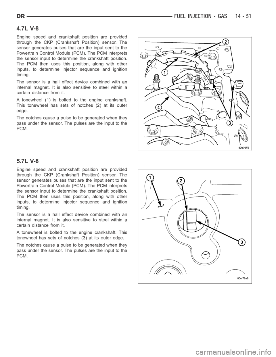
4.7L V-8
Engine speed and crankshaft position are provided
through the CKP (Crankshaft Position) sensor. The
sensor generates pulses that are the input sent to the
Powertrain Control Module (PCM). The PCM interprets
the sensor input to determine the crankshaft position.
The PCM then uses this position, along with other
inputs, to determine injector sequence and ignition
timing.
The sensor is a hall effect device combined with an
internal magnet. It is also sensitive to steel within a
certain distance from it.
A tonewheel (1) is bolted to the engine crankshaft.
This tonewheel has sets of notches (2) at its outer
edge.
The notches cause a pulse to be generated when they
pass under the sensor. The pulses are the input to the
PCM.
5.7L V-8
Engine speed and crankshaft position are provided
through the CKP (Crankshaft Position) sensor. The
sensor generates pulses that are the input sent to the
Powertrain Control Module (PCM). The PCM interprets
the sensor input to determine the crankshaft position.
The PCM then uses this position, along with other
inputs, to determine injector sequence and ignition
timing.
The sensor is a hall effect device combined with an
internal magnet. It is also sensitive to steel within a
certain distance from it.
A tonewheel is bolted to the engine crankshaft. This
tonewheel has sets of notches (3) at its outer edge.
The notches cause a pulse to be generated when they
pass under the sensor. The pulses are the input to the
PCM.
Page 2344 of 5267

WARNING: The fuel injection pump supplies extremely high fuel pressure toeach individual injector
through the high-pressure lines. Fuel under this amount of pressure can penetrate the skin and cause per-
sonal injury. Wear safety goggles and adequate protective clothing. Do not loosen fuel fittings while engine
is running.
WARNING: Engine may start while cranking starter motor.
DRAINING FUEL TANK - DIESEL
Due to a one-way check valve installed into the fuel fill opening fitting atthe tank, the tank cannot be drained con-
ventionally at the fill cap.
1. Raise vehicle.
2. If vehicle is equipped with 4 doors and a 6 foot (short) box, remove left-rear tire/wheel.
3. Thoroughly clean area at top of fuel tank around fuel tank module.
4. Loosen clamp and disconnect rubber fuel fill hose at tank.
5. Drain fuel tank by attaching drain hose from an approved diesel fuel draining station to the fuel fill fitting of tank.
SPECIFICATIONS
FUEL INJECTOR FIRING ORDER - DIESEL
1–5–3–6–2–4
TORQUE
DESCRIPTION N-m Ft. Lbs. In. Lbs.
Crankshaft Position
Sensor980
Camshaft Position Sensor 9 - 80
Engine Coolant
Temperature Sensor18 13 160
Rear Engine Lift Bracket
Bolts77 56 -
Fuel Connector Nut at
Cylinder Head50 37 -
Fuel Filler Hose Clamp at
Ta n k3-27
Fuel Filler Housing-to-
Body Screws2-17
Fuel Filter Lid 34 25 -
Fuel Filter Drain Valve
Screws1.5 - 14
Fuel Heater Element
Screws1.5 - 14
Fuel Line Banjo Fitting
Bolts24 18 -
Screened Banjo Bolt 24 18 -
Fuel Line Banjo Fitting
Bolts at Fuel Filter
Housing24 18 -
Page 2370 of 5267
INSTALLATION
1. If fuel tank is to be replaced, install fuel tank mod-
ule into tank. (Refer to 14 - FUEL SYSTEM/FUEL
DELIVERY/FUEL TANK MODULE - REMOVAL).
2. Position fuel tank (1) to hydraulic jack.
3. Raise tank until positioned near body.
4. Connect fuel tank module electrical connector at
top of tank.
5. Connect fuel supply and return lines to tank mod-
ule.
6. Continue raising tank until positioned snug to body.
7. Install and position both tank support straps (4).
Install 2 fuel tank strap nuts and tighten to 41 Nꞏm
(30 ft. lbs.).Tighten rear strap nut first.
8. Remove hydraulic jack.
9. Connect rubber fill hose to fuel fill tube and tighten
clamp.
10. Install tire / wheel (if necessary).
11. Lower vehicle.
12. Fill fuel tank with fuel.
13. Start engine and check for fuel leaks near top of module.
Page 2380 of 5267

SENSOR-CAMSHAFT POSITION
DESCRIPTION
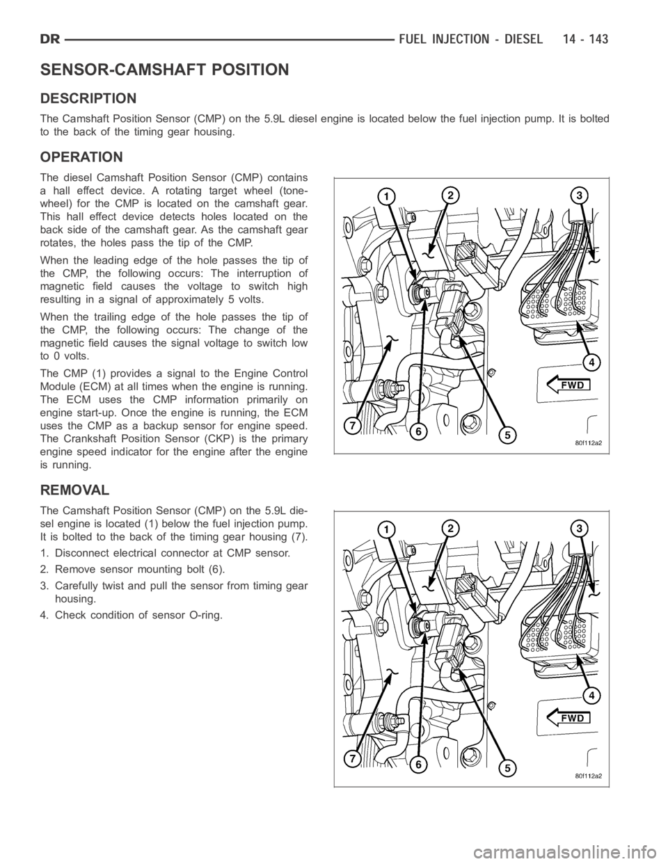
The Camshaft Position Sensor (CMP) on the 5.9L diesel engine is located below the fuel injection pump. It is bolted
to the back of the timing gear housing.
OPERATION
The diesel Camshaft Position Sensor (CMP) contains
a hall effect device. A rotating target wheel (tone-
wheel) for the CMP is located on the camshaft gear.
This hall effect device detects holes located on the
back side of the camshaft gear. As the camshaft gear
rotates, the holes pass the tip of the CMP.
When the leading edge of the hole passes the tip of
the CMP, the following occurs: The interruption of
magnetic field causes the voltage to switch high
resulting in a signal of approximately 5 volts.
When the trailing edge of the hole passes the tip of
the CMP, the following occurs: The change of the
magnetic field causes the signal voltage to switch low
to 0 volts.
The CMP (1) provides a signal to the Engine Control
Module (ECM) at all times when the engine is running.
TheECMusestheCMPinformationprimarilyon
engine start-up. Once the engine is running, the ECM
uses the CMP as a backup sensor for engine speed.
The Crankshaft Position Sensor (CKP) is the primary
engine speed indicator for the engine after the engine
is running.
REMOVAL
The Camshaft Position Sensor (CMP) on the 5.9L die-
sel engine is located (1) below the fuel injection pump.
It is bolted to the back of the timing gear housing (7).
1. Disconnect electrical connector at CMP sensor.
2. Remove sensor mounting bolt (6).
3. Carefully twist and pull the sensor from timing gear
housing.
4. Check condition of sensor O-ring.
Page 2382 of 5267

SENSOR-CRANKSHAFT POSITION
DESCRIPTION
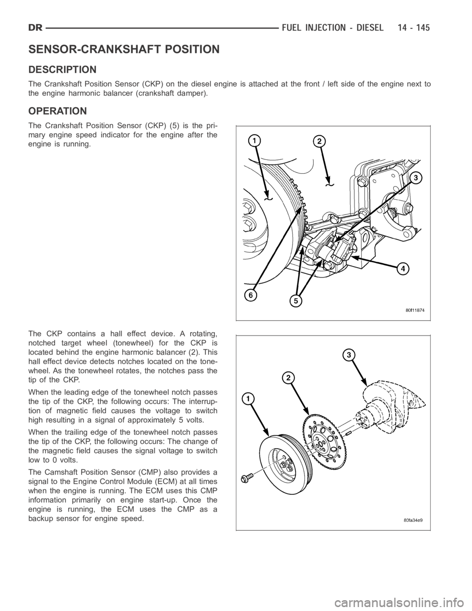
The Crankshaft Position Sensor (CKP) on the diesel engine is attached at thefront/leftsideoftheenginenextto
the engine harmonic balancer (crankshaft damper).
OPERATION
The Crankshaft Position Sensor (CKP) (5) is the pri-
mary engine speed indicator for the engine after the
engine is running.
The CKP contains a hall effect device. A rotating,
notched target wheel (tonewheel) for the CKP is
located behind the engine harmonic balancer (2). This
hall effect device detects notches located on the tone-
wheel. As the tonewheel rotates, the notches pass the
tip of the CKP.
When the leading edge of the tonewheel notch passes
the tip of the CKP, the following occurs: The interrup-
tion of magnetic field causes the voltage to switch
high resulting in a signal of approximately 5 volts.
When the trailing edge of the tonewheel notch passes
the tip of the CKP, the following occurs: The change of
the magnetic field causes the signal voltage to switch
lowto0volts.
The Camshaft Position Sensor (CMP) also provides a
signal to the Engine Control Module (ECM) at all times
when the engine is running. The ECM uses this CMP
information primarily on engine start-up. Once the
engine is running, the ECM uses the CMP as a
backup sensor for engine speed.