Page 2125 of 5267
3. Carefully position retainer/oil seal (1) to block.
Tighten the retainer bolts to 11 Nꞏm (95 in. lbs.).
4. Install flywheel and clutch (Refer to 6 - CLUTCH/
CLUTCH DISC - INSTALLATION).
5. Install transmission (Refer to 21 - TRANSMISSION/
TRANSAXLE/MANUAL - INSTALLATION).
Page 2134 of 5267
BEARING-CRANKSHAFT PILOT
REMOVAL
1. Remove transmission (Refer to 21 - TRANSMIS-
SION/TRANSAXLE/MANUAL - REMOVAL).
2. Remove clutch and flywheel (Refer to 6 - CLUTCH/
CLUTCH DISC - REMOVAL).
3. Using Special Tools 8990 (1) and C-3752 (2),
remove pilot bearing from crankshaft.
INSTALLATION
NOTE: New pilot bearing has special grease
packed into bearing. Do not wash grease from
bearing. Install bearing with part number markings
(1) facing out.
Page 2135 of 5267
1. Install pilot bearing with Special Tools 9058 (1) and
C-4171 (2).
2. Install flywheel and clutch (Refer to 6 - CLUTCH/
CLUTCH DISC - INSTALLATION).
3. Install transmission (Refer to 21 - TRANSMISSION/
TRANSAXLE/MANUAL - INSTALLATION).
Page 2160 of 5267

TURBOCHARGER SYSTEM
DIAGNOSIS AND TESTING
TURBOCHARGER BOOST PRESSURE
Low turbocharger boost pressure can cause poor engine performance and driveability concerns. The following pro-
cedure will test the turbocharger boost pressure.
Causes of low boost pressure include the following:
Restricted air inlet system
Leak in charge air cooler system
Restricted/high pressure drop across charge air cooler
Damaged turbocharger compressor wheel housing
Turbocharger wastegate stuck open
Excessive exhaust restriction
Causes of excessively high boost pressure include:
Turbocharger wastegate stuck closed
Turbocharger wastegate signal line leaking or damaged
Damaged wastegate command valve O-rings
Wastegate command valve mechanically stuck in actuated position
Several Diagnostic Trouble Codes (DTCs) can be set that will indicate highor low system boost levels. There is a
DTC for circuit faults relating to the electronically controlled wastegate command valve.
(Refer to 11 - EXHAUST SYSTEM/TURBOCHARGER SYSTEM/CHARGE AIR COOLER AND PLUMBING - DIAG-
NOSIS AND TESTING) for diagnosing of low or high boost pressure due to leaks.
NOTE: If oil is present on either the inlet or exhaust side of the turbo charger, check the charge air cooler
for evidence of oil. Clean charge air cooler of any oil before starting the engine. Failure to do this can result
in severe engine damage.
Page 2162 of 5267

OPERATION
Exhaust gas pressure and energy drive the turbine,
which in turn drives a centrifugal compressor that
compresses the inlet air, and forces the air into the
engine through the charge air cooler and plumbing.
Since heat is a by-product of this compression, the air
must pass through a charge air cooler to cool the
incoming air and maintain power and efficiency.
Increasing air flow to the engine provides:
Improved engine performance
Lower exhaust smoke density
Improved operating economy
Altitude compensation
Noise reduction.
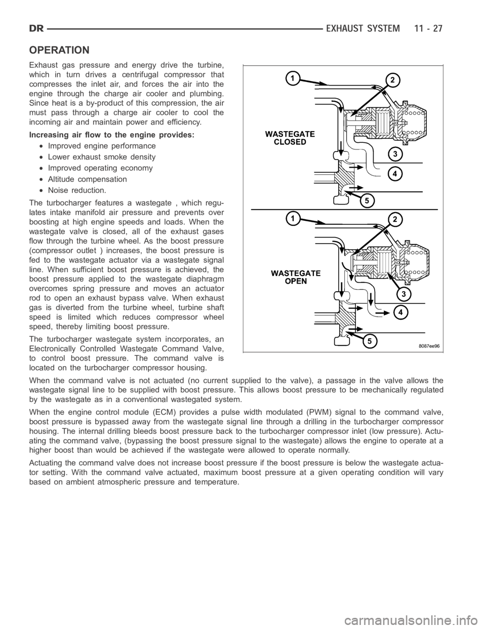
The turbocharger features a wastegate , which regu-
lates intake manifold air pressure and prevents over
boosting at high engine speeds and loads. When the
wastegate valve is closed, all of the exhaust gases
flow through the turbine wheel. As the boost pressure
(compressor outlet ) increases, the boost pressure is
fed to the wastegate actuator via a wastegate signal
line. When sufficient boost pressure is achieved, the
boost pressure applied to the wastegate diaphragm
overcomes spring pressure and moves an actuator
rod to open an exhaust bypass valve. When exhaust
gas is diverted from the turbine wheel, turbine shaft
speed is limited which reduces compressor wheel
speed, thereby limiting boost pressure.
The turbocharger wastegate system incorporates, an
Electronically Controlled Wastegate Command Valve,
to control boost pressure. The command valve is
located on the turbocharger compressor housing.
When the command valve is not actuated (no current supplied to the valve), apassage in the valve allows the
wastegate signal line to be supplied with boost pressure. This allows boost pressure to be mechanically regulated
by the wastegate as in a conventional wastegated system.
When the engine control module (ECM) provides a pulse width modulated (PWM) signal to the command valve,
boost pressure is bypassed away from the wastegate signal line through a drilling in the turbocharger compressor
housing. The internal drilling bleeds boost pressure back to the turbocharger compressor inlet (low pressure). Actu-
ating the command valve, (bypassing the boost pressure signal to the wastegate) allows the engine to operate at a
higher boost than would be achieved if the wastegate were allowed to operate normally.
Actuating the command valve does not increase boost pressure if the boost pressure is below the wastegate actua-
tor setting. With the command valve actuated, maximum boost pressure at a given operating condition will vary
based on ambient atmospheric pressure and temperature.
Page 2165 of 5267

TURBOCHARGER OIL DRAIN TUBE
NOTE: If oil is present on either the inlet or
exhaust side of the turbo charger, check the
charge air cooler for evidence of oil. Clean charge
air cooler of any oil before starting the engine.
Failure to do this can result in severe engine dam-
age.
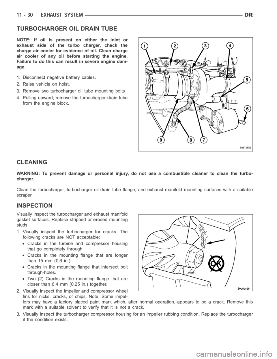
1. Disconnect negative battery cables.
2. Raise vehicle on hoist.
3. Remove two turbocharger oil tube mounting bolts
4. Pulling upward, remove the turbocharger drain tube
from the engine block.
CLEANING
WARNING: To prevent damage or personal injury, do not use a combustible cleaner to clean the turbo-
charger.
Clean the turbocharger, turbocharger oil drain tube flange, and exhaust manifold mounting surfaces with a suitable
scraper.
INSPECTION
Visually inspect the turbocharger and exhaust manifold
gasket surfaces. Replace stripped or eroded mounting
studs.
1. Visually inspect the turbocharger for cracks. The
following cracks are NOT acceptable:
Cracks in the turbine and compressor housing
that go completely through.
Cracks in the mounting flange that are longer
than 15 mm (0.6 in.).
Cracks in the mounting flange that intersect bolt
through-holes.
Two (2) Cracks in the mounting flange that are
closer than 6.4 mm (0.25 in.) together.
2. Visually inspect the impeller and compressor wheel
fins for nicks, cracks, or chips. Note: Some impel-
lers may have a factory placed paint mark which, after normal operation, appears to be a crack. Remove this
mark with a suitable solvent to verify that it is not a crack.
3. Visually inspect the turbocharger compressor housing for an impeller rubbing condition. Replace the turbocharger
if the condition exists.
Page 2166 of 5267

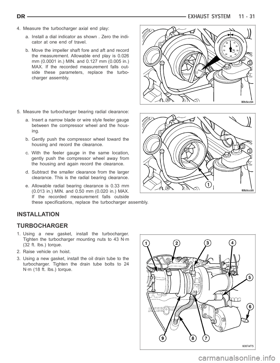
4. Measure the turbocharger axial end play:
a. Install a dial indicator as shown . Zero the indi-
cator at one end of travel.
b. Move the impeller shaft fore and aft and record
the measurement. Allowable end play is 0.026
mm (0.0001 in.) MIN. and 0.127 mm (0.005 in.)
MAX. If the recorded measurement falls out-
side these parameters, replace the turbo-
charger assembly.
5. Measure the turbocharger bearing radial clearance:
a. Insert a narrow blade or wire style feeler gauge
between the compressor wheel and the hous-
ing.
b. Gently push the compressor wheel toward the
housing and record the clearance.
c. With the feeler gauge in the same location,
gently push the compressor wheel away from
the housing and again record the clearance.
d. Subtract the smaller clearance from the larger
clearance. This is the radial bearing clearance.
e. Allowable radial bearing clearance is 0.33 mm
(0.013 in.) MIN. and 0.50 mm (0.020 in.) MAX.
If the recorded measurement falls outside
these specifications, replace the turbocharger assembly.
INSTALLATION
TURBOCHARGER
1. Using a new gasket, install the turbocharger.
Tighten the turbocharger mounting nuts to 43 Nꞏm
(32 ft. lbs.) torque.
2. Raise vehicle on hoist.
3. Using a new gasket, install the oil drain tube to the
turbocharger. Tighten the drain tube bolts to 24
Nꞏm (18 ft. lbs.) torque.
Page 2177 of 5267
FRONT BUMPER
REMOVAL
1. Using a grease pencil or equivalent, mark the posi-
tion of the bumper support bracket (5) on the frame
rail tip (7) to aid installation.
2. Disconnect the fog lamp electrical connector at the
left frame rail.
3. Support the bumper with a suitable lifting device.
4. Remove the bumper support bracket (5) nuts and
bolts (8 and 9) and remove bumper.
INSTALLATION
1. Install the bumper onto the frame rails (7) and posi-
tion the wheelhouse splash shield into the support
brackets (4).
2. Install the bolts and nuts (8 and 9).
3. Line up the bumper with the marks made previ-
ously and tighten the bolts and nuts to 95 Nꞏm (70
ft. lbs.).
4. Check and adjust the bumper alignment as neces-
sary (Refer to 23 - BODY/BODY STRUCTURE/
GAP AND FLUSH - SPECIFICATIONS).