Page 2045 of 5267

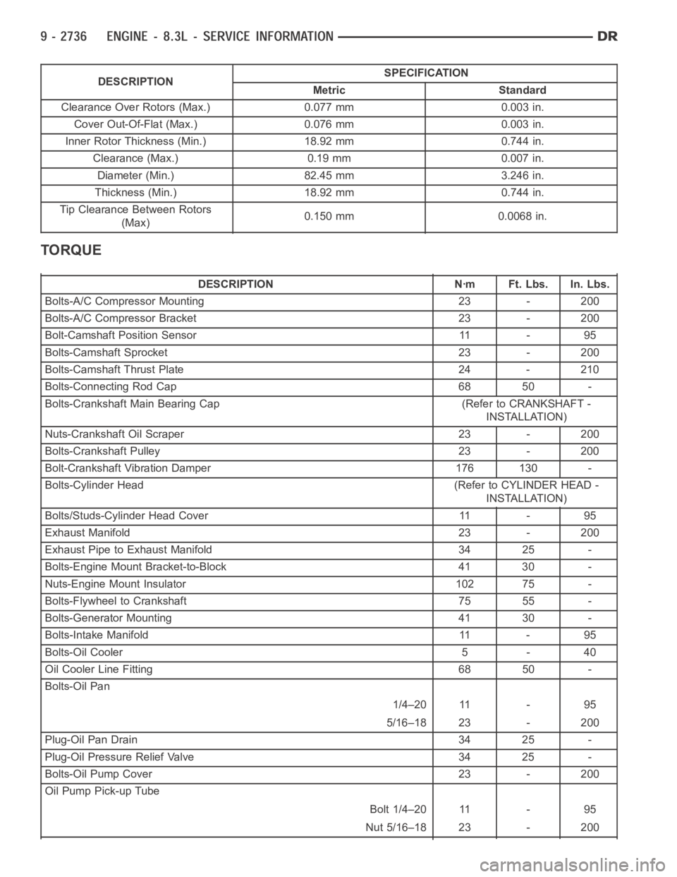
DESCRIPTIONSPECIFICATION
Metric Standard
Clearance Over Rotors (Max.) 0.077 mm 0.003 in.
Cover Out-Of-Flat (Max.) 0.076 mm 0.003 in.
Inner Rotor Thickness (Min.) 18.92 mm 0.744 in.
Clearance (Max.) 0.19 mm 0.007 in.
Diameter (Min.) 82.45 mm 3.246 in.
Thickness (Min.) 18.92 mm 0.744 in.
Tip Clearance Between Rotors
(Max)0.150 mm 0.0068 in.
TORQUE
DESCRIPTION Nꞏm Ft. Lbs. In. Lbs.
Bolts-A/C Compressor Mounting 23 - 200
Bolts-A/C Compressor Bracket 23 - 200
Bolt-Camshaft Position Sensor 11 - 95
Bolts-Camshaft Sprocket 23 - 200
Bolts-Camshaft Thrust Plate 24 - 210
Bolts-Connecting Rod Cap 68 50 -
Bolts-Crankshaft Main Bearing Cap (Refer to CRANKSHAFT -
INSTALLATION)
Nuts-Crankshaft Oil Scraper 23 - 200
Bolts-Crankshaft Pulley 23 - 200
Bolt-Crankshaft Vibration Damper 176 130 -
Bolts-Cylinder Head (Refer to CYLINDER HEAD -
INSTALLATION)
Bolts/Studs-Cylinder Head Cover 11 - 95
Exhaust Manifold 23 - 200
Exhaust Pipe to Exhaust Manifold 34 25 -
Bolts-Engine Mount Bracket-to-Block 41 30 -
Nuts-Engine Mount Insulator 102 75 -
Bolts-Flywheel to Crankshaft 75 55 -
Bolts-Generator Mounting 41 30 -
Bolts-Intake Manifold 11 - 95
Bolts-Oil Cooler 5 - 40
Oil Cooler Line Fitting 68 50 -
Bolts-Oil Pan
1/4–20 11 - 95
5/16–18 23 - 200
Plug-Oil Pan Drain 34 25 -
Plug-Oil Pressure Relief Valve 34 25 -
Bolts-Oil Pump Cover 23 - 200
Oil Pump Pick-up Tube
Bolt 1/4–20 11 - 95
Nut 5/16–18 23 - 200
Page 2078 of 5267

COVER-TIMING CHAIN
REMOVAL
1. Disconnect negative battery cable.
2. Disconnect throttle body air inlet duct at the throttle
body, CCV hose, disconnect the IAT sensor and
remove air cleaner housing cover (Refer to 9 -
ENGINE/AIR INTAKE SYSTEM - REMOVAL).
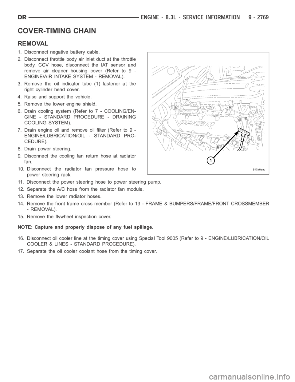
3. Remove the oil indicator tube (1) fastener at the
right cylinder head cover.
4. Raise and support the vehicle.
5. Remove the lower engine shield.
6. Drain cooling system (Refer to 7 - COOLING/EN-
GINE - STANDARD PROCEDURE - DRAINING
COOLING SYSTEM).
7. Drain engine oil and remove oil filter (Refer to 9 -
ENGINE/LUBRICATION/OIL - STANDARD PRO-
CEDURE).
8. Drain power steering.
9. Disconnect the cooling fan return hose at radiator
fan.
10. Disconnect the radiator fan pressure hose to
power steering rack.
11. Disconnect the power steering hose to power steering pump.
12. Separate the A/C hose from the radiator fan module.
13. Remove the lower radiator hoses.
14. Remove the front frame cross member (Refer to 13 - FRAME & BUMPERS/FRAME/FRONT CROSSMEMBER
- REMOVAL).
15. Remove the flywheel inspection cover.
NOTE: Capture and properly dispose of any fuel spillage.
16. Disconnect oil cooler line at the timing cover using Special Tool 9005 (Refer to 9 - ENGINE/LUBRICATION/OIL
COOLER & LINES - STANDARD PROCEDURE).
17. Separate the oil cooler coolant hose from the timing cover.
Page 2081 of 5267

5. Hand start bolts No.1 and No.2.
6. Loosely install A/C compressor mounting bracket.
7. Hand start remaining timing chain cover bolts.
8. Torque timing chain cover bolts in the sequence
showninto23Nꞏm(200in.lbs.).
9. Torque A/C compressor mounting bracket bolts to
23 Nꞏm (200 in. lbs.).
10. Install crankshaft oil seal (Refer to 9 - ENGINE/
ENGINE BLOCK/CRANKSHAFT OIL SEAL -
FRONT - INSTALLATION).
11. Raise vehicle on hoist.
12. Install oil pump pick up tube using anewo-ring.
Torque 1/4–20 bolt to 11 Nꞏm (95 in. lbs.). Torque
5/16–18 nuts to 23 Nꞏm (200 in. lbs.).
13. Support the engine with a jack stand.
14. Install oil pan and drain plug (Refer to 9 -
ENGINE/LUBRICATION/OIL PAN - INSTALLA-
TION).
15. Remove the jackstand.
16. Tighten the engine mount to frame nuts to 102
Nꞏm (75 ft.lbs.).
17. Connect the oil cooler coolant hose to the timing
cover.
18. Connect the oil cooler line (Refer to 9 - ENGINE/
LUBRICATION/OIL COOLER & LINES - STAN-
DARD PROCEDURE).
19. Install the lower radiator hose.
20. Install the flywheel inspection cover.
21. Install the front frame cross member (Refer to 13
- FRAME & BUMPERS/FRAME/FRONT CROSS-
MEMBER - INSTALLATION).
22. Lower vehicle.
23. Position the compressor and install A/C compressor mounting bolts. Torque bolts to 23 Nꞏm (200 in. lbs.).
24. Connect heater hose at timing cover.
25. Install crankshaft damper and pulley (Refer to 9 - ENGINE/ENGINE BLOCK/VIBRATION DAMPER - INSTAL-
LATION).
26. Install generator. Connect electrical connectors.
27. Install the idler pulley.
28. Connect the camshaft position sensor wiring harness connector.
29. Connect engine coolant temperature (ECT) sensor wiring harness connector.
30. Install power steering pump mounting bolts.
31. Install accessory drive belt (Refer to 7 - COOLING/ACCESSORY DRIVE/DRIVE BELTS - INSTALLATION).
32. Install the radiator fan assembly (Refer to 7 - COOLING/ENGINE/RADIATOR FAN - INSTALLATION).
Page 2083 of 5267
TIMING CHAIN AND SPROCKETS
REMOVAL
TIMING CHAIN AND CAMSHAFT SPROCKET REMOVAL
1. Remove timing chain cover (Refer to 9 - ENGINE/
VALVE TIMING/TIMING CHAIN COVER -
REMOVAL).
2. Rotate crankshaft until timing marks are aligned.
3. Remove the camshaft sprocket attaching bolts (2).
4. Remove the timing chain (1) with camshaft
sprocket (2).
CRANKSHAFT SPROCKET REMOVAL
1. Install Special Tool 8194 into end of crankshaft.
Lubricate the end of Special Tool 8194 with wheel
bearing grease or equivalent.
NOTE: Lubricate the threads of Special Tool 5048
using Mopar
Nickel Anti-seize Compound or
equivalent, before beginning crankshaft sprocket
removal.
Page 2093 of 5267
PA N - O I L
REMOVAL
1. Disconnect the negative battery cable.
2. Disconnect engine oil indicator tube fastener from
the right cylinder head cover.
3. Install engine lifting fixture TOOL 9363 and support
TOOL.
4. Raise vehicle on hoist.
5. Remove the lower engine shield.
6. Drain engine oil.
7. Remove the front cross member (Refer to 13 -
FRAME & BUMPERS/FRAME/FRONT CROSS-
MEMBER - REMOVAL)
8. Remove flywheel inspection cover.
9. Loosen engine mount through bolts.
10. Wiggle and separate the oil level indicator tube
from the oil pan.
NOTE: Careful positioning of the jack stand is nec-
essary to prevent damage to other components
Page 2095 of 5267
2. Apply an 1/8 in. bead of Mopar Engine RTV at the two joints between the cylinder block to timing chain case
cover and the two joints between the rear main seal retainer and engine block.
3. Position oil pan and gasket to engine block, seat the oil level indicatortube in the oil pan and hand start all
fasteners.
4. Tighten the transmission to oil pan bolts in finger
tight.
5. Torque 5/16-18 oil pan bolts to 23 Nꞏm (200 in.
lbs.). Torque 1/4-20 oil pan bolts to 11 Nꞏm (95 in
lbs.).
6. Torque transmission to oil pan bolts to 23 Nꞏm (200
in. lbs.).
7. Lower the engine.
8. Install and tighten engine mount through bolts to
102 Nꞏm (75 ft. lbs.).
9. Install flywheel inspection cover.
Page 2121 of 5267
DAMPER-CRANKSHAFT
REMOVAL
1. Raise and support the vehicle.
2. Remove the engine front shield.
3. Disconnect the radiator fan hydraulic lines (Refer to
7 - COOLING/ENGINE/RADIATOR FAN -
REMOVAL).
4. Lower vehicle.
5. Disconnect the air inlet duct, IAT sensor, CCV hose
at the throttle body, and remove the air cleaner
housing cover.
6. Remove accessory drive belt (Refer to 7 - COOL-
ING/ACCESSORY DRIVE/DRIVE BELTS -
REMOVAL).
7. Remove the radiator fan (Refer to 7 - COOLING/
ENGINE/RADIATOR FAN - REMOVAL).
8. Raise and support the vehicle.
9. Remove crankshaft pulley.
10. Remove crankshaft damper bolt.
11. Install crankshaft insert, Special Tool 8194 (1).
Lubricate the end of Special Tool 8194 (1) with
wheel bearing grease or equivalent.
NOTE: Lubricate the threads of the puller using
Mopar
Nickel Anti-seize Compound or equivalent,
before beginning crankshaft damper removal.
12. Using a bolt-grip type universal puller (1), remove
the crankshaft damper.
Page 2124 of 5267
SEAL-OIL-REAR-CRANK AND RETAINER
REMOVAL
1. Remove transmission (Refer to 21 - TRANSMIS-
SION/TRANSAXLE/MANUAL - REMOVAL).
2. Remove clutch and flywheel (Refer to 6 - CLUTCH/
CLUTCH DISC - REMOVAL).
NOTE: The oil seal and retainer are serviced as an
assembly.
3. Remove the seal retainer bolts from cylinder block
and oil pan.
4. Remove the oil seal and retainer (1) assembly.
INSTALLATION
1. Clean the engine block and retainer. Make sure
surfaces are clean and free of oil.
2. Install Special Tool 9060 (1) (seal guide) onto end
of crankshaft. Align hole in tool with dowel pin on
crankshaft.