2006 DODGE RAM SRT-10 oil level
[x] Cancel search: oil levelPage 2025 of 5267
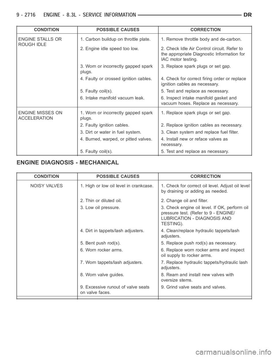
CONDITION POSSIBLE CAUSES CORRECTION
ENGINE STALLS OR
ROUGH IDLE1. Carbon buildup on throttle plate. 1. Remove throttle body and de-carbon.
2. Engine idle speed too low. 2. Check Idle Air Control circuit. Refer to
the appropriate Diagnostic Information for
IAC motor testing.
3. Worn or incorrectly gapped spark
plugs.3. Replace spark plugs or set gap.
4. Faulty or crossed ignition cables. 4. Check for correct firing order or replace
ignition cables as necessary.
5. Faulty coil(s). 5. Test and replace as necessary.
6. Intake manifold vacuum leak. 6. Inspect intake manifold gasket and
vacuum hoses. Replace as necessary.
ENGINE MISSES ON
ACCELERATION1. Worn or incorrectly gapped spark
plugs.1. Replace spark plugs or set gap.
2. Faulty ignition cables. 2. Replace ignition cables as necessary.
3. Dirt or water in fuel system. 3. Clean system and replace fuel filter.
4. Burned, warped, or pitted valves. 4. Install new or reface valves as
necessary.
5. Faulty coil(s). 5. Test and replace as necessary.
ENGINE DIAGNOSIS - MECHANICAL
CONDITION POSSIBLE CAUSES CORRECTION
NOISY VALVES 1. High or low oil level incrankcase. 1. Check for correct oil level. Adjust oil level
by draining or adding as needed.
2. Thin or diluted oil. 2. Change oil and filter.
3. Low oil pressure. 3. Check engine oil level. If OK, perform oil
pressure test. (Refer to 9 - ENGINE/
LUBRICATION - DIAGNOSIS AND
TESTING).
4. Dirt in tappets/lash adjusters. 4. Clean/replace hydraulic tappets/lash
adjusters.
5. Bent push rod(s). 5. Replace push rod(s) as necessary.
6. Worn rocker arms. 6. Replace worn rocker arms and inspect
oil supply to rocker arms.
7. Worn tappets/lash adjusters. 7. Replace hydraulic tappets/hydrauliclash
adjusters.
8. Worn valve guides. 8. Ream and install new valves with
oversize stems.
9. Excessive runout of valve seats
on valve faces.9. Grind valve seats and valves.
Page 2026 of 5267
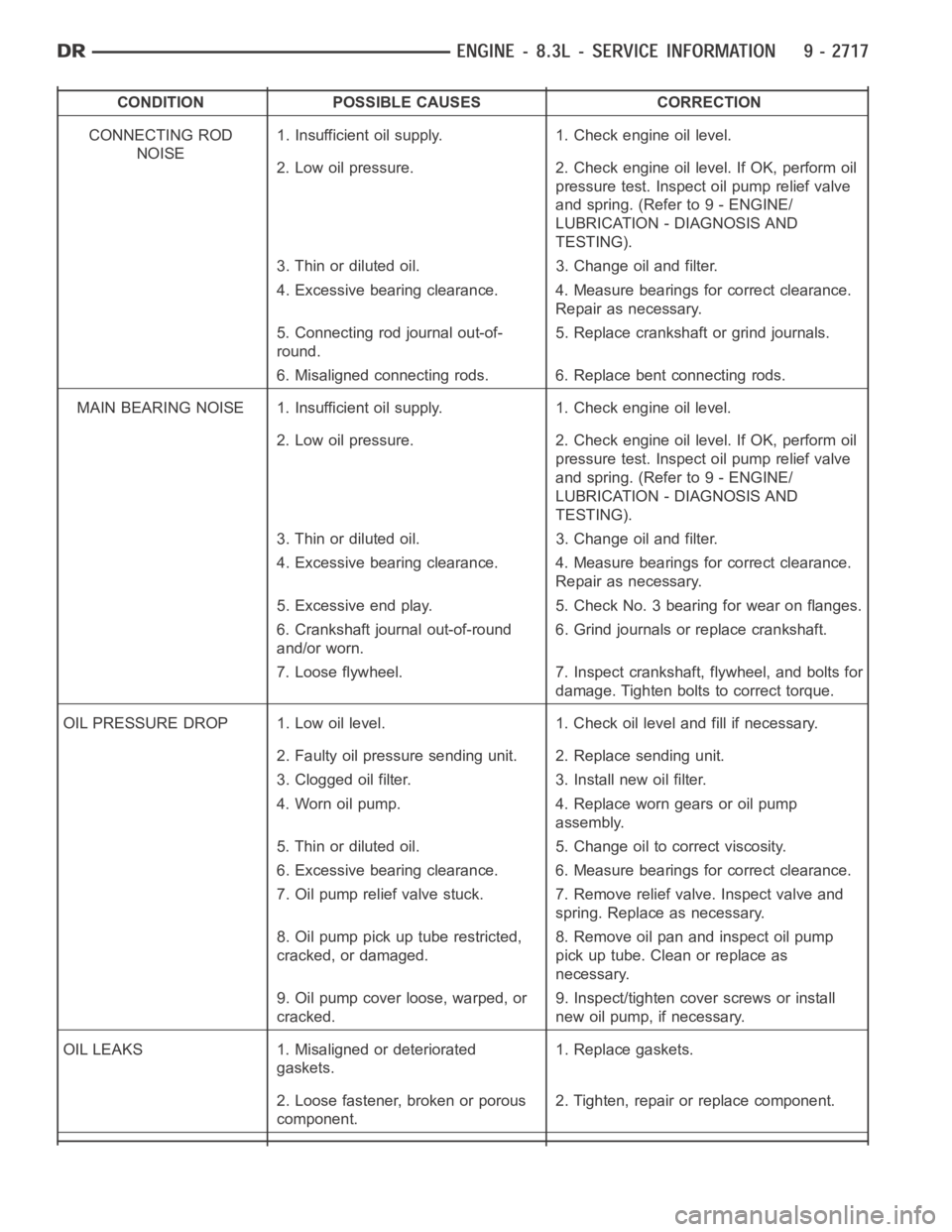
CONDITION POSSIBLE CAUSES CORRECTION
CONNECTING ROD
NOISE1. Insufficient oil supply. 1. Check engine oil level.
2. Low oil pressure. 2. Check engine oil level. If OK, perform oil
pressure test. Inspect oil pump relief valve
and spring. (Refer to 9 - ENGINE/
LUBRICATION - DIAGNOSIS AND
TESTING).
3. Thin or diluted oil. 3. Change oil and filter.
4. Excessive bearing clearance. 4. Measure bearings for correct clearance.
Repair as necessary.
5. Connecting rod journal out-of-
round.5. Replace crankshaft or grind journals.
6. Misaligned connecting rods. 6. Replace bent connecting rods.
MAIN BEARING NOISE 1. Insufficient oil supply. 1. Check engine oil level.
2. Low oil pressure. 2. Check engine oil level. If OK, perform oil
pressure test. Inspect oil pump relief valve
and spring. (Refer to 9 - ENGINE/
LUBRICATION - DIAGNOSIS AND
TESTING).
3. Thin or diluted oil. 3. Change oil and filter.
4. Excessive bearing clearance. 4. Measure bearings for correct clearance.
Repair as necessary.
5. Excessive end play. 5. Check No. 3 bearing for wear on flanges.
6. Crankshaft journal out-of-round
and/or worn.6. Grind journals or replace crankshaft.
7. Loose flywheel. 7. Inspect crankshaft, flywheel, and bolts for
damage. Tighten bolts to correct torque.
OIL PRESSURE DROP 1. Low oil level. 1. Check oil level and fill if necessary.
2. Faulty oil pressure sending unit. 2. Replace sending unit.
3. Clogged oil filter. 3. Install new oil filter.
4. Worn oil pump. 4. Replace worn gears or oil pump
assembly.
5. Thin or diluted oil. 5. Change oil to correct viscosity.
6. Excessive bearing clearance. 6. Measure bearings for correct clearance.
7. Oil pump relief valve stuck. 7. Remove relief valve. Inspect valve and
spring. Replace as necessary.
8. Oil pump pick up tube restricted,
cracked, or damaged.8. Remove oil pan and inspect oil pump
pick up tube. Clean or replace as
necessary.
9. Oil pump cover loose, warped, or
cracked.9. Inspect/tighten cover screws or install
new oil pump, if necessary.
OIL LEAKS 1. Misaligned or deteriorated
gaskets.1. Replace gaskets.
2. Loose fastener, broken or porous
component.2. Tighten, repair or replace component.
Page 2027 of 5267
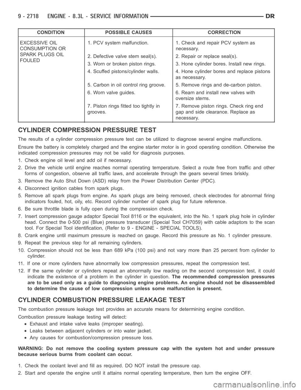
CONDITION POSSIBLE CAUSES CORRECTION
EXCESSIVE OIL
CONSUMPTION OR
SPARK PLUGS OIL
FOULED1. PCV system malfunction. 1. Check and repair PCV system as
necessary.
2. Defective valve stem seal(s). 2. Repair or replace seal(s).
3. Worn or broken piston rings. 3. Hone cylinder bores. Install new rings.
4. Scuffed pistons/cylinder walls. 4. Hone cylinder bores and replace pistons
as necessary.
5. Carbon in oil control ring groove. 5. Remove rings and de-carbon piston.
6. Worn valve guides. 6. Ream and install new valves with
oversize stems.
7. Piston rings fitted too tightly in
grooves.7. Remove piston rings. Check ring end
gap and side clearance. Replace as
necessary.
CYLINDER COMPRESSION PRESSURE TEST
The results of a cylinder compressionpressure test can be utilized to diagnose several engine malfunctions.
Ensurethebatteryiscompletelychargedandtheenginestartermotorisingood operating condition. Otherwise the
indicated compression pressures may not be valid for diagnosis purposes.
1. Check engine oil level and add oil if necessary.
2. Drive the vehicle until engine reaches normal operating temperature. Select a route free from traffic and other
forms of congestion, observe all traffic laws, and accelerate through thegears several times briskly.
3. Remove the Auto Shut Down (ASD) relay from the Power Distribution Center(PDC).
4. Disconnect ignition cables from spark plugs.
5. Remove all spark plugs from engine. As spark plugs are being removed, check electrodes for abnormal firing
indicators fouled, hot, oily, etc. Record cylinder number of spark plug for future reference.
6. Be sure throttle blade is fully open during the compression check.
7. Insert compression gauge adaptor Special Tool 8116 or the equivalent, into the No. 1 spark plug hole in cylinder
head. Connect the 0-500 psi (Blue) pressure transducer (Special Tool CH7059) with cable adaptors to the scan
tool. For Special Tool identification, (Refer to 9 - ENGINE - SPECIAL TOOLS).
8. Crank engine until maximum pressure is reached on gauge. Record this pressure as No. 1 cylinder pressure.
9. Repeat the previous step for all remaining cylinders.
10. Compression should not be less than 689 kPa (100 psi) and not vary more than 25 percent from cylinder to
cylinder.
11. If one or more cylinders have abnormally low compression pressures, repeat the compression test.
12. If the same cylinder or cylinders repeat an abnormally low reading on the second compression test, it could
indicate the existence of a problem in the cylinder in question.The recommended compression pressures
are to be used only as a guide to diagnosing engine problems. An engine should not be disassembled
to determine the cause of low compression unless some malfunction is present.
CYLINDER COMBUSTIONPRESSURE LEAKAGE TEST
The combustion pressure leakage test provides an accurate means for determining engine condition.
Combustion pressure leakage testing will detect:
Exhaust and intake valve leaks (improper seating).
Leaks between adjacent cylinders or into water jacket.
Any causes for combustion/compression pressure loss.
WARNING: Do not remove the cooling system pressure cap with the system hot and under pressure
because serious burns from coolant can occur.
1. Check the coolant level and fill as required. DO NOT install the pressurecap.
2. Start and operate the engine until it attains normal operating temperature, then turn the engine OFF.
Page 2029 of 5267
CHEMICAL TEST METHOD
Combustion leaks into the cooling system can also be checked by using Bloc-Chek Kit C-3685-A or equivalent.
Perform test following the procedures supplied with the tool kit.
HYDRAULIC TAPPET NOISE DIAGNOSIS
PRELIMINARY STEP TO CHECKING THE HYDRAULIC TAPPETS
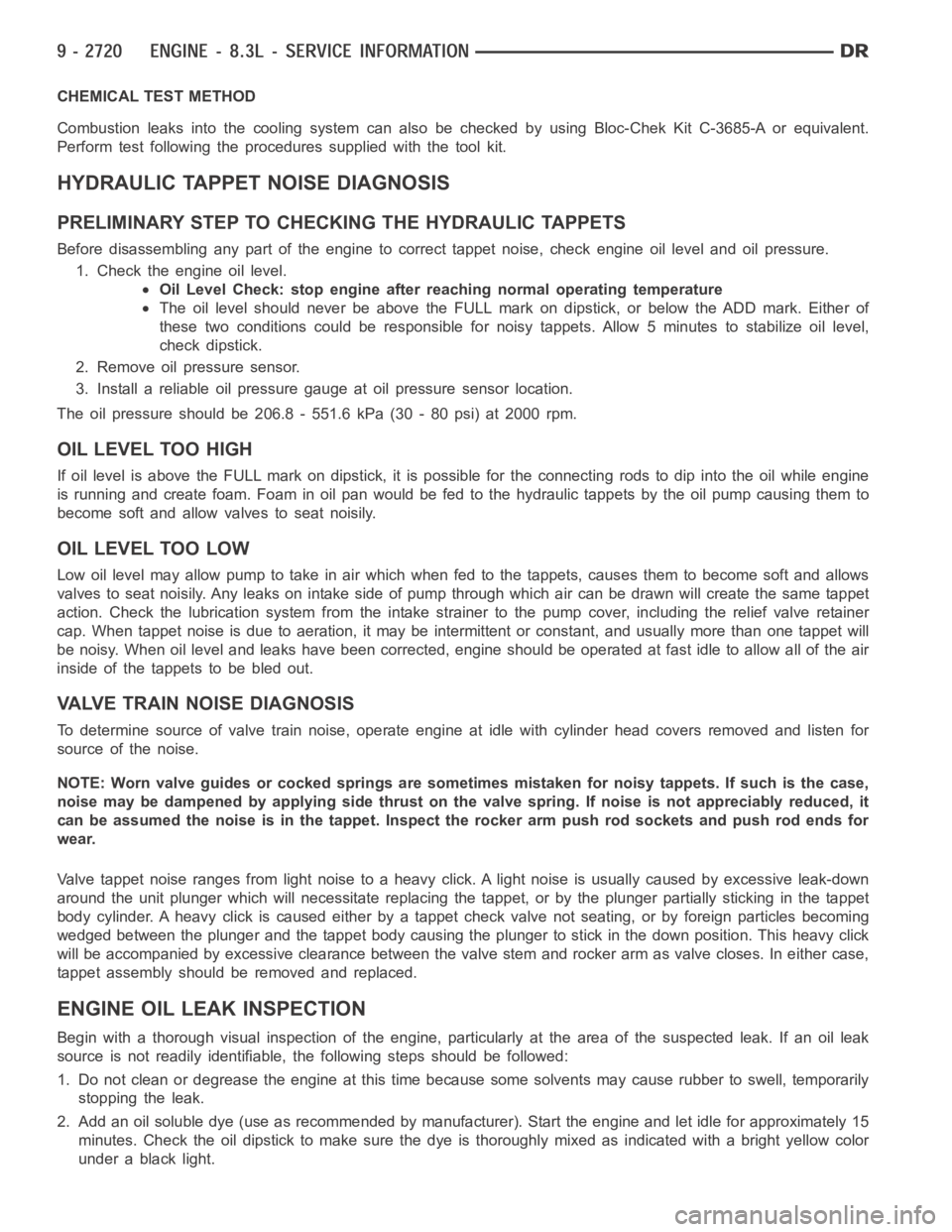
Before disassembling any part of the engine to correct tappet noise, checkengine oil level and oil pressure.
1. Check the engine oil level.
Oil Level Check: stop engine after reaching normal operating temperature
The oil level should never be above the FULL mark on dipstick, or below the ADD mark. Either of
these two conditions could be responsible for noisy tappets. Allow 5 minutes to stabilize oil level,
check dipstick.
2. Remove oil pressure sensor.
3. Install a reliable oil pressure gauge at oil pressure sensor location.
The oil pressure should be 206.8 - 551.6 kPa (30 - 80 psi) at 2000 rpm.
OIL LEVEL TOO HIGH
If oil level is above the FULL mark on dipstick, it is possible for the connecting rods to dip into the oil while engine
is running and create foam. Foam in oil pan would be fed to the hydraulic tappets by the oil pump causing them to
become soft and allow valves to seat noisily.
OIL LEVEL TOO LOW
Low oil level may allow pump to take in air which when fed to the tappets, causes them to become soft and allows
valves to seat noisily. Any leaks on intake side of pump through which air canbedrawnwillcreatethesametappet
action. Check the lubrication system from the intake strainer to the pump cover, including the relief valve retainer
cap. When tappet noise is due to aeration, it may be intermittent or constant, and usually more than one tappet will
be noisy. When oil level and leaks have been corrected, engine should be operated at fast idle to allow all of the air
inside of the tappets to be bled out.
VALVE TRAIN NOISE DIAGNOSIS
To determine source of valve train noise, operate engine at idle with cylinder head covers removed and listen for
source of the noise.
NOTE: Worn valve guides or cocked springs are sometimes mistaken for noisytappets. If such is the case,
noise may be dampened by applying side thrust on the valve spring. If noise is not appreciably reduced, it
can be assumed the noise is in the tappet. Inspect the rocker arm push rod sockets and push rod ends for
wear.
Valve tappet noise ranges from light noise to a heavy click. A light noise isusually caused by excessive leak-down
around the unit plunger which will necessitate replacing the tappet, or bythe plunger partially sticking in the tappet
body cylinder. A heavy click is caused either by a tappet check valve not seating, or by foreign particles becoming
wedged between the plunger and the tappet body causing the plunger to stickin the down position. This heavy click
will be accompanied by excessive clearance between the valve stem and rocker arm as valve closes. In either case,
tappet assembly should be removed and replaced.
ENGINE OIL LEAK INSPECTION
Begin with a thorough visual inspection of the engine, particularly at thearea of the suspected leak. If an oil leak
source is not readily identifiable, thefollowingstepsshouldbefollowed:
1. Do not clean or degrease the engine at this time because some solvents maycause rubber to swell, temporarily
stopping the leak.
2. Add an oil soluble dye (use as recommended by manufacturer). Start the engine and let idle for approximately 15
minutes. Check the oil dipstick to make sure the dye is thoroughly mixed as indicated with a bright yellow color
under a black light.
Page 2040 of 5267
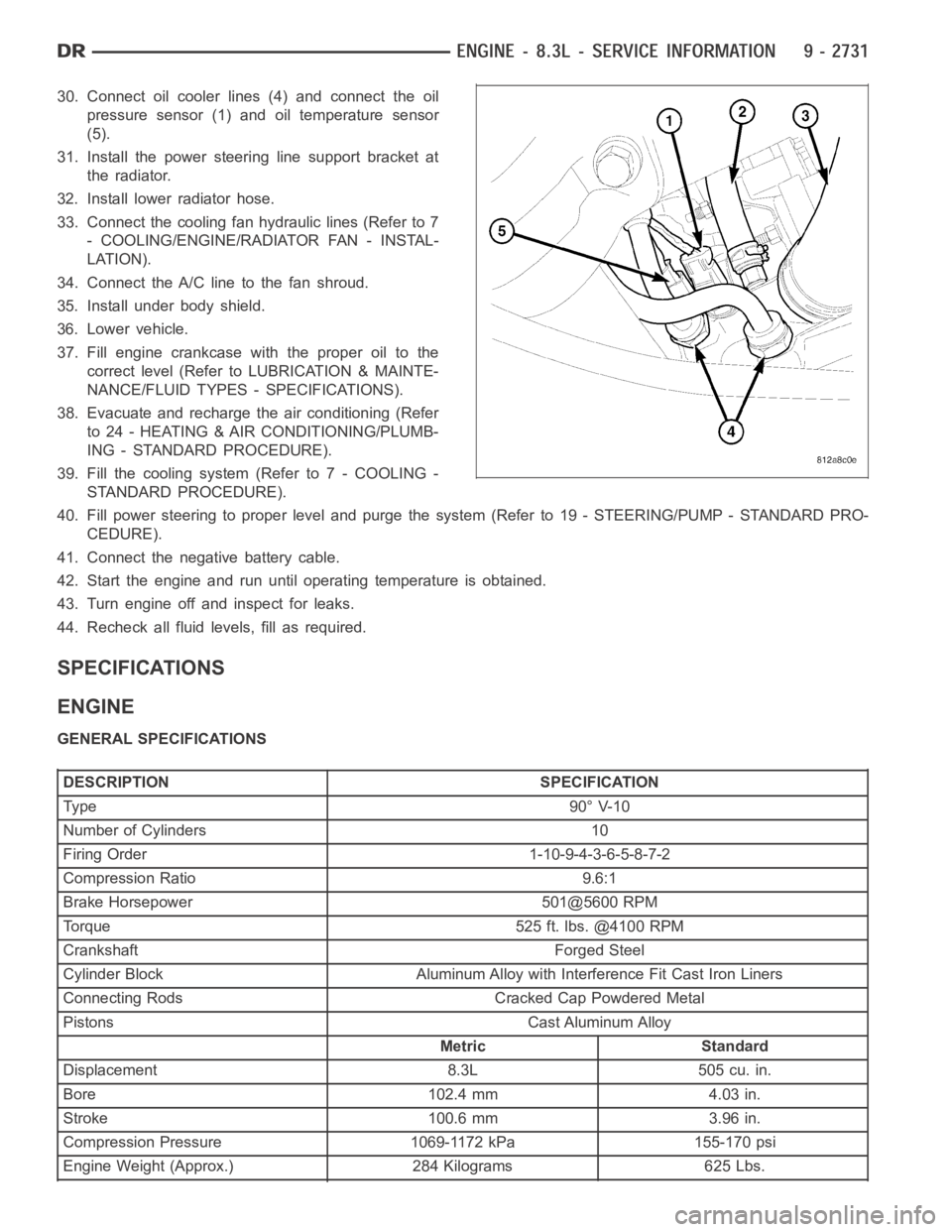
30. Connect oil cooler lines (4) and connect the oil
pressure sensor (1) and oil temperature sensor
(5).
31. Install the power steering line support bracket at
the radiator.
32. Install lower radiator hose.
33. Connect the cooling fan hydraulic lines (Refer to 7
- COOLING/ENGINE/RADIATOR FAN - INSTAL-
LATION).
34. Connect the A/C line to the fan shroud.
35. Install under body shield.
36. Lower vehicle.
37. Fill engine crankcase with the proper oil to the
correct level (Refer to LUBRICATION & MAINTE-
NANCE/FLUID TYPES - SPECIFICATIONS).
38. Evacuate and recharge the air conditioning (Refer
to 24 - HEATING & AIR CONDITIONING/PLUMB-
ING - STANDARD PROCEDURE).
39. Fill the cooling system (Refer to 7 - COOLING -
STANDARD PROCEDURE).
40. Fill power steering to proper leveland purge the system (Refer to 19 - STEERING/PUMP - STANDARD PRO-
CEDURE).
41. Connect the negative battery cable.
42. Start the engine and run until operating temperature is obtained.
43. Turn engine off and inspect for leaks.
44. Recheck all fluid levels, fill as required.
SPECIFICATIONS
ENGINE
GENERAL SPECIFICATIONS
DESCRIPTION SPECIFICATION
Ty pe 9 0° V-1 0
Number of Cylinders 10
Firing Order 1-10-9-4-3-6-5-8-7-2
Compression Ratio 9.6:1
Brake Horsepower 501@5600 RPM
Torque 525 ft. lbs. @4100 RPM
Crankshaft Forged Steel
Cylinder Block Aluminum Alloy with Interference Fit Cast Iron Liners
Connecting Rods Cracked Cap Powdered Metal
Pistons Cast Aluminum Alloy
Metric Standard
Displacement 8.3L 505 cu. in.
Bore 102.4 mm 4.03 in.
Stroke 100.6 mm 3.96 in.
Compression Pressure 1069-1172 kPa 155-170 psi
Engine Weight (Approx.) 284 Kilograms 625 Lbs.
Page 2064 of 5267
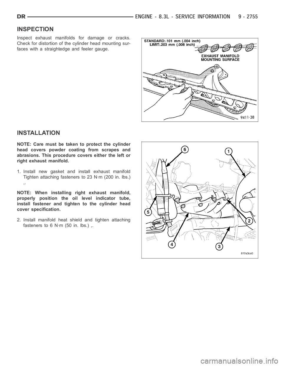
INSPECTION
Inspect exhaust manifolds for damage or cracks.
Check for distortion of the cylinder head mounting sur-
faces with a straightedge and feeler gauge.
INSTALLATION
NOTE: Care must be taken to protect the cylinder
head covers powder coating from scrapes and
abrasions. This procedure covers either the left or
right exhaust manifold.
1. Install new gasket and install exhaust manifold
Tighten attaching fasteners to 23 Nꞏm (200 in. lbs.)
,.
NOTE: When installing right exhaust manifold,
properly position the oil level indicator tube,
install fastener and tighten to the cylinder head
cover specification.
2. Install manifold heat shield and tighten attaching
fasteners to 6 Nꞏm (50 in. lbs.) ,.
Page 2066 of 5267
HEAD(S)-CYLINDER
REMOVAL - CYLINDER HEAD(S)
NOTE: Care must be taken to protect the intake
manifold and cylinder head covers powder coating
from scrapes and abrasions. This procedure cov-
ers either the left or right cylinder head.
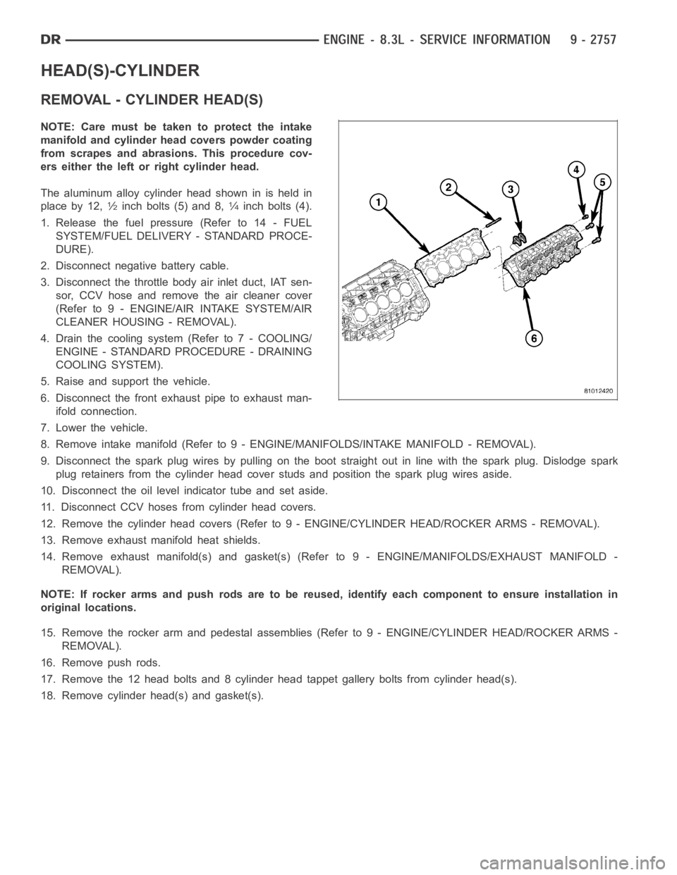
The aluminum alloy cylinder head shown in is held in
place by 12,
1⁄2inch bolts (5) and 8,1⁄4inch bolts (4).
1. Release the fuel pressure (Refer to 14 - FUEL
SYSTEM/FUEL DELIVERY - STANDARD PROCE-
DURE).
2. Disconnect negative battery cable.
3. Disconnect the throttle body air inlet duct, IAT sen-
sor, CCV hose and remove the air cleaner cover
(Refer to 9 - ENGINE/AIR INTAKE SYSTEM/AIR
CLEANER HOUSING - REMOVAL).
4. Drain the cooling system (Refer to 7 - COOLING/
ENGINE - STANDARD PROCEDURE - DRAINING
COOLING SYSTEM).
5. Raise and support the vehicle.
6. Disconnect the front exhaust pipe to exhaust man-
ifold connection.
7. Lower the vehicle.
8. Remove intake manifold (Refer to 9 - ENGINE/MANIFOLDS/INTAKE MANIFOLD-REMOVAL).
9. Disconnect the spark plug wires by pulling on the boot straight out in line with the spark plug. Dislodge spark
plug retainers from the cylinder head cover studs and position the spark plug wires aside.
10. Disconnect the oil level indicator tube and set aside.
11. Disconnect CCV hoses from cylinder head covers.
12. Remove the cylinder head covers (Refer to 9 - ENGINE/CYLINDER HEAD/ROCKER ARMS - REMOVAL).
13. Remove exhaust manifold heat shields.
14. Remove exhaust manifold(s) and gasket(s) (Refer to 9 - ENGINE/MANIFOLDS/EXHAUST MANIFOLD -
REMOVAL).
NOTE: If rocker arms and push rods are to be reused, identify each componentto ensure installation in
original locations.
15. Remove the rocker arm and pedestal assemblies (Refer to 9 - ENGINE/CYLINDER HEAD/ROCKER ARMS -
REMOVAL).
16. Remove push rods.
17. Remove the 12 head bolts and 8 cylinder head tappet gallery bolts from cylinder head(s).
18. Remove cylinder head(s) and gasket(s).
Page 2068 of 5267
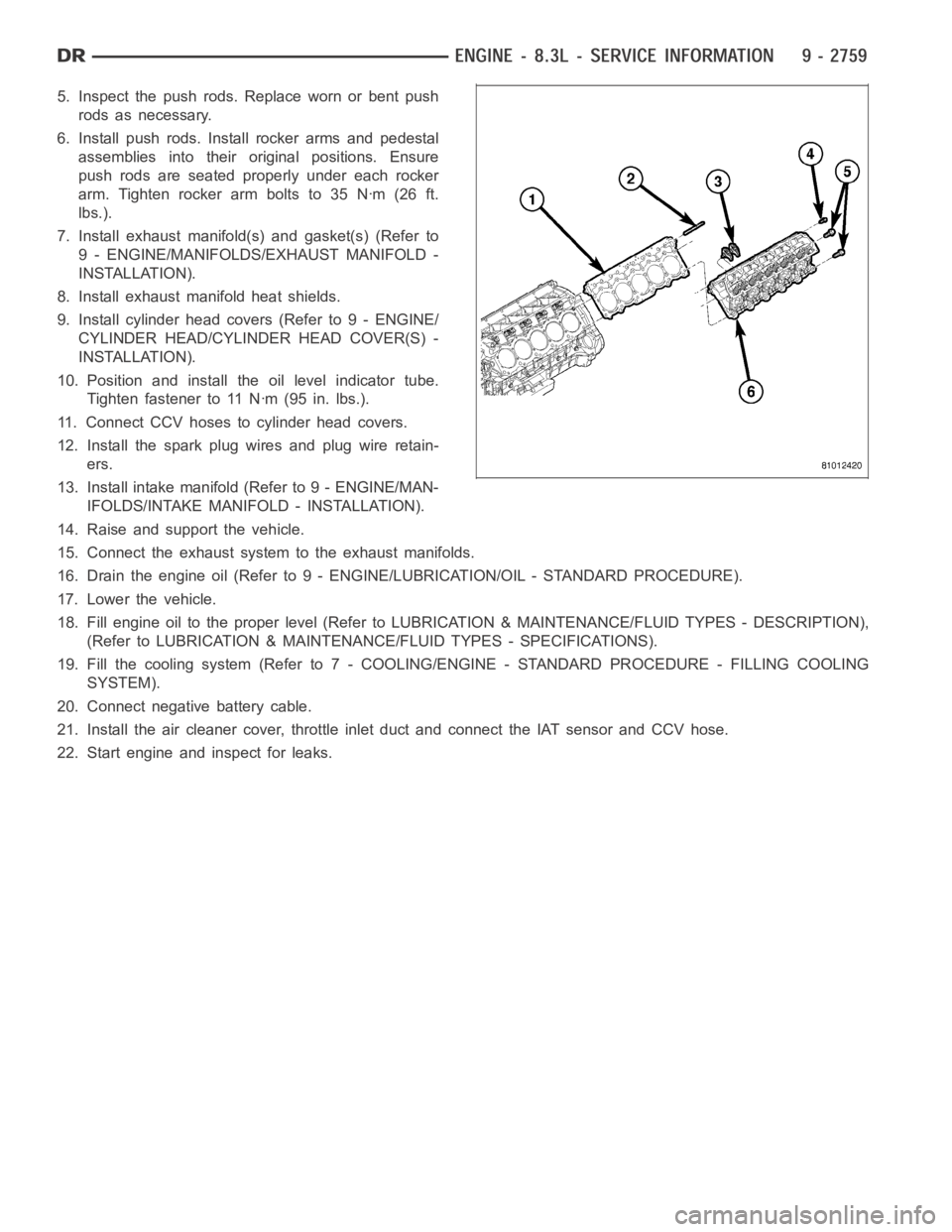
5. Inspect the push rods. Replace worn or bent push
rods as necessary.
6. Install push rods. Install rocker arms and pedestal
assemblies into their original positions. Ensure
push rods are seated properly under each rocker
arm.Tightenrockerarmboltsto35Nꞏm(26ft.
lbs.).
7. Install exhaust manifold(s) and gasket(s) (Refer to
9 - ENGINE/MANIFOLDS/EXHAUST MANIFOLD -
INSTALLATION).
8. Install exhaust manifold heat shields.
9. Install cylinder head covers (Refer to 9 - ENGINE/
CYLINDER HEAD/CYLINDER HEAD COVER(S) -
INSTALLATION).
10. Position and install the oil level indicator tube.
Tighten fastener to 11 Nꞏm (95 in. lbs.).
11. Connect CCV hoses to cylinder head covers.
12. Install the spark plug wires and plug wire retain-
ers.
13. Install intake manifold (Refer to 9 - ENGINE/MAN-
IFOLDS/INTAKE MANIFOLD - INSTALLATION).
14. Raise and support the vehicle.
15. Connect the exhaust systemto the exhaust manifolds.
16. Drain the engine oil (Refer to 9 - ENGINE/LUBRICATION/OIL - STANDARD PROCEDURE).
17. Lower the vehicle.
18. Fill engine oil to the proper level (Refer to LUBRICATION & MAINTENANCE/FLUID TYPES - DESCRIPTION),
(Refer to LUBRICATION & MAINTENANCE/FLUID TYPES - SPECIFICATIONS).
19. Fill the cooling system (Refer to 7 - COOLING/ENGINE - STANDARD PROCEDURE - FILLING COOLING
SYSTEM).
20. Connect negative battery cable.
21. Install the air cleaner cover, throttle inlet duct and connect the IAT sensor and CCV hose.
22. Start engine and inspect for leaks.