2006 DODGE RAM SRT-10 oil level
[x] Cancel search: oil levelPage 1904 of 5267
SEAL - CRANKSHAFT OIL - FRONT
REMOVAL ................................. 2667
INSTALLATION ............................. 2668
SEAL - CRANKSHAFT OIL - REAR
REMOVAL ................................. 2670
INSTALLATION ............................. 2670
RETAINER - CRANK REAR OIL SEAL
REMOVAL ................................. 2671
INSTALLATION ............................. 2671
TAPPETS - VALVE
REMOVAL ................................. 2673
CLEANING ................................. 2674
INSPECTION ............................... 2674
INSTALLATION ............................. 2674
PISTON & CONNECTING ROD
DESCRIPTION ............................. 2677
STANDARD PROCEDURE - HEAD GASKET
SELECTION .............................. 2677
REMOVAL ................................. 2678
CLEANING—PISTON AND CONNECTING ROD . 2678
INSPECTION
INSPECTION - PISTONS .................. 2678
INSPECTION - CONNECTING ROD........ 2680
INSTALLATION ............................. 2680
RINGS - PISTON
STANDARD PROCEDURE - PISTON RING
FITTING .................................. 2682
DAMPER - CRANKSHAFT
REMOVAL ................................. 2684
INSPECTION ............................... 2684
INSTALLATION ............................. 2684
MOUNT - FRONT
REMOVAL ................................. 2685
INSTALLATION ............................. 2686
MOUNT - REAR
REMOVAL ................................. 2687
INSTALLATION ............................. 2687
LUBRICATION
DESCRIPTION ............................. 2688
OPERATION ............................... 2688
DIAGNOSIS AND TESTING—ENGINE OIL
PRESSURE .............................. 2692
OIL
STANDARD PROCEDURE
STANDARD PROCEDURE - ENGINE OIL
LEVEL................................... 2693STANDARD PROCEDURE - ENGINE OIL
SERVICE................................. 2693
COOLER - ENGINE OIL & LINES
CLEANING
CLEANING AND INSPECTION............. 2694
FILTER - ENGINE OIL
REMOVAL ................................. 2695
INSTALLATION ............................. 2695
PA N - E N G I N E O I L
REMOVAL ................................. 2696
CLEANING ................................. 2696
INSPECTION............................... 2696
INSTALLATION ............................. 2696
VALVE-OILPRESSURERELIEF
REMOVAL ................................. 2697
CLEANING ................................. 2697
INSPECTION............................... 2697
INSTALLATION ............................. 2697
SWITCH - OIL PRESSURE
REMOVAL ................................. 2698
INSTALLATION ............................. 2698
PUMP - ENGINE OIL
REMOVAL ................................. 2699
CLEANING ................................. 2699
INSPECTION............................... 2699
INSTALLATION ............................. 2700
MANIFOLD - INTAKE
REMOVAL ................................. 2702
CLEANING ................................. 2703
INSPECTION............................... 2703
INSTALLATION ............................. 2703
MANIFOLD - EXHAUST
REMOVAL ................................. 2704
CLEANING ................................. 2704
INSPECTION............................... 2704
INSTALLATION ............................. 2704
VALVE TIMING
STANDARD PROCEDURE - TIMING
VERIFICATION ........................... 2706
CASE - FRONT
REMOVAL ................................. 2707
INSTALLATION ............................. 2708
COVER - TIMING
REMOVAL ................................. 2710
INSTALLATION ............................. 2710
Page 1906 of 5267
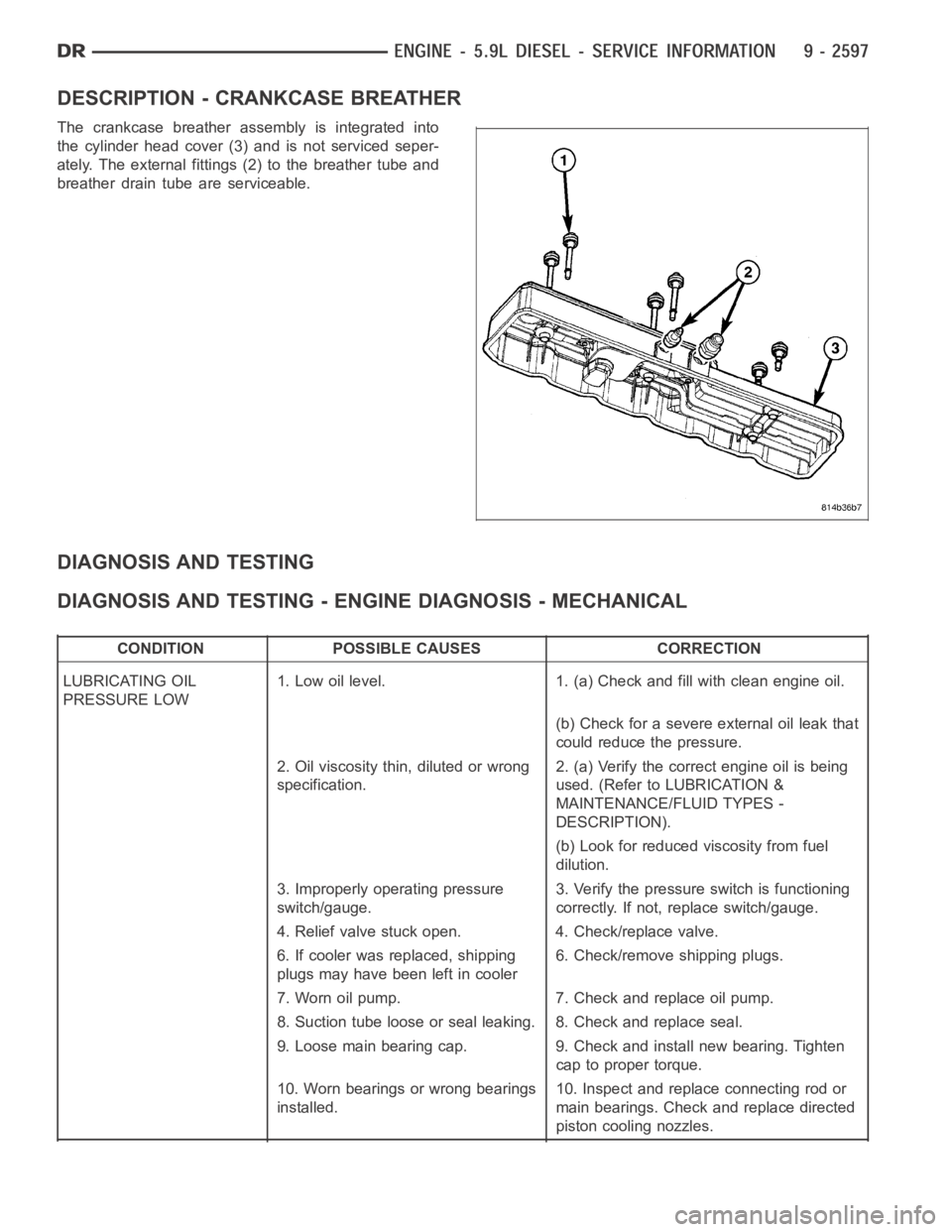
DESCRIPTION - CRANKCASE BREATHER
The crankcase breather assembly is integrated into
the cylinder head cover (3) and is not serviced seper-
ately. The external fittings (2) to the breather tube and
breather drain tube are serviceable.
DIAGNOSIS AND TESTING
DIAGNOSIS AND TESTING - ENGINE DIAGNOSIS - MECHANICAL
CONDITION POSSIBLE CAUSES CORRECTION
LUBRICATING OIL
PRESSURE LOW1. Low oil level. 1. (a) Check and fill with clean engine oil.
(b) Check for a severe external oil leak that
could reduce the pressure.
2. Oil viscosity thin, diluted or wrong
specification.2. (a) Verify the correct engine oil is being
used. (Refer to LUBRICATION &
MAINTENANCE/FLUID TYPES -
DESCRIPTION).
(b) Look for reduced viscosity from fuel
dilution.
3. Improperly operating pressure
switch/gauge.3. Verify the pressure switch is functioning
correctly. If not, replace switch/gauge.
4. Relief valve stuck open. 4. Check/replace valve.
6. If cooler was replaced, shipping
plugs may have been left in cooler6. Check/remove shipping plugs.
7. Worn oil pump. 7. Check and replace oil pump.
8. Suction tube loose or seal leaking. 8. Check and replace seal.
9. Loose main bearing cap. 9. Check and install new bearing. Tighten
cap to proper torque.
10. Worn bearings or wrong bearings
installed.10. Inspect and replace connecting rod or
main bearings. Check and replace directed
piston cooling nozzles.
Page 1933 of 5267
CYLINDER HEAD
DESCRIPTION
The cylinder head is constructed of cast iron and is a one piece cross flow design with four valves per cylinder. The
arrangement of two intake and two exhaust valves per cylinder allows for a centrally located injector. The cylinder
head also includes an integral intake manifold, an integral thermostat housing, and a longitudal fuel return rifle,
which exits at the rear of the head. The 24 valve design also includes integrally cast valve guides and hardened
intake and exhaust valve seat inserts.
REMOVAL
1. Disconnect battery negative cables.
2. Raise vehicle on hoist.
3. Drain engine coolant.
4. Disconnect exhaust pipe from turbocharger elbow.
5. Remove turbocharger drain tube bolts at turbocharger. Cap off ports to prevent dirt or foreign material from enter-
ing.
6. Lower vehicle.
7. Disconnect air inlet temperature/pressure sensor.
8. Remove air cleaner housing and snorkel from the vehicle. Cap off turbocharger air inlet to prevent intrusion of
dirt or foreign material.
9. Disconnect cab heater core supply and return hoses from the cylinder head and heater pipe.
10. Disconnect turbocharger oil supply line at the turbocharger end. Cap off open ports to prevent intrusion of dirt
or foreign material.
11. Remove exhaust manifold-to-cylinder head bolts, spacers, heat shield, retention straps, and cab heater plumb-
ing. Remove exhaust manifold and turbocharger from the vehicle as an assembly.
12. Remove cooling fan/drive/shroud assembly. (Refer to 7 - COOLING/ENGINE/RADIATOR FAN - REMOVAL)
13. Remove accessory drive belt (Refer to 7 - COOLING/ACCESSORY DRIVE/DRIVE BELTS - REMOVAL).
14. Remove cooling fan support from cylinder block.
15. Remove upper generator bolt, loosen lower generator bolt, and rotate generator away from cylinder head.
16. Disconnect radiator upper hose from the thermostat housing.
17. Disconnect the Intake Air Temperature/Manifold Air Pressure, and Coolant Temperature sensor connectors.
18. Remove the engine harness to cylinder head attaching bolts and P-clipsat front of head.
19. Remove the intake air grid heater wires from the grid heater.
20. Remove engine oil level indicator tube attaching bolt at fuel filter housing bracket and inlet air connection..
21. Remove the charge air cooler-to-air inlet housing pipe.
22. Remove the engine wire harness attaching bolt and wire harness push-infastener from air inlet housing.
23. Remove the air inlet housing and intake grid heater from the intake manifold cover.
24. Remove the two grid heater harness-to-cylinder head attaching bolts at front of cylinder head.
NOTE: Extreme care should be used to keep dirt/debris from entering the fuel lines. Plastic caps should be
used on the ends of the fuel lines.
25.Remove the high pressure pump to fuel rail fuel line as follows:
a. Loosen fuel line nuts at fuel pump and at fuel rail.
b. Use a back-up wrench on the fitting at the fuel pump to keep it from loosening.
26. Remove the fuel rail to cylinder head fuel lines as follows:
a. Loosen No. 6 high pressure fuel line shield and position out of way.
b. Loosen the fuel line nuts at the fuel rail and at the cylinder head. Use a back-up wrench on HPC nut.
c. Remove the fuel line bracket bolts at the intake manifold cover.
Page 1939 of 5267
d. Install fuel line brace bolts-to-intake manifold finger tight for fuellines#2thru#5.
e. Install fuel line brace nut to rear lift bracket stud, finger tight, for fuel line #6.
f. Hand tighten fuel pump to fuel rail line.
g. Torque fuel line nuts at cylinder head to 30 Nꞏm ( 22 ft. lbs.).
h. Torque fuel line nuts at fuel rail to 30 Nꞏm (22 ft. lbs.)
i. Usingabackupwrench,torquefuelpumptofuelraillineto37Nꞏm(27ft.lbs.). At injection pump.
j. Torque fuel pump to fuel rail line to 37 Nꞏm (27 ft. lbs.) at fuel rail.
k. Torque fuel drain banjo bolt at pressure limiting valve and front of fuelfilter housing to 24 Nꞏm (18 ft. lbs.).
l. Torque fuel line brace bolts to 24 Nꞏm (18 ft. lbs.).
m. Torque fuel line brace nut to 24 Nꞏm (18 ft. lbs.).
n. Torque rail bolts to 24 Nꞏm (18 ft. lbs.).
o. Connect fuel pressure sensor.
p. Torque fuel filter mounting bolts to 24 Nꞏm (18 ft. lbs.).
19. Reposition number 6 fuel line shield and torque to 43 Nꞏm (32 ft. lbs.).
20. Install the fuel filter to injection pump low pressure line. Inspect and replace sealing washers if necessary.
Torque banjo bolts to 24 Nꞏm (18 ft. lbs.).
21. Connect fuel return line at back of cylinder head hand tight.
22. Connect fuel return line at filter housing hand tight.
23. Torque banjo connections at cylinder head and fuel filter housing to 24Nꞏm (18 ft. lbs.)
24. Install bracket to rear of filter housing. Torque to 24 Nꞏm (18 ft. lbs.).
25. Using new gaskets, install the intake grid heater and air inlet housing. Torque bolts to 24 Nꞏm (18 ft. lbs.).
26. Install wire harness P-clip and push on clip to air inlet housing.
27. Connect engine oil level indicator tube at fuel filter housing and at air inlet housing.
28. Install the charge air cooler-to-air inlet housing duct assembly. Torque all clamps to 11 Nꞏm (100 in. lbs.).
29. Connect intake grid heater wires.
30. Secure engine harness to front of cylinder head with bolt at four locations.
31. Connect engine coolant temperature sensor connector.
32. Connect radiator upper hose to thermostat housing.
33. Rotate generator into position. Install upper bolt and torque upper and lower bolts.
34. Install wire harness push-on clip below bracket.
35. Install wire harness P-clip to top of bracket.
36. Install fan support and torque to 32 Nꞏm (24 ft. lbs.).
37. Install cooling fan/drive refer to (Refer to 7 - COOLING/ENGINE/RADIATOR FAN - INSTALLATION).
38. Install accessory drive belt (Refer to 7 - COOLING/ACCESSORY DRIVE/DRIVE BELTS - INSTALLATION).
39. Install exhaust manifold/turbocharger assembly, using new gaskets.Start all bolts/spacers by hand. Starting
from the center bolts out, Torque bolts to 43 Nꞏm (32 ft. lbs.), then retorque from the center out again.
40. Install exhaust manifold heat shield to exhaust manifold studs. Install retaining nuts.Torque to 24 Nꞏm (18 ft.
lbs.).
41. Install exhaust bolt retention straps across cylinders 5 & 6.
42. Using a new gasket, connect the turbocharger oil drain tube. Torque to 24Nꞏm(18ft.lbs.).
43. Perform the turbocharger pre-lube procedure. (Refer to 11 - EXHAUST SYSTEM/TURBOCHARGER SYSTEM/
TURBOCHARGER - INSTALLATION)
44. Connect the turbocharger oil supply line. Torque to 24 Nꞏm (18 ft. lbs.).
45. Install air cleaner housing and duct.
46. Connect air inlet temperature/pressure sensor.
47. Raise vehicle on hoist.
Page 1979 of 5267
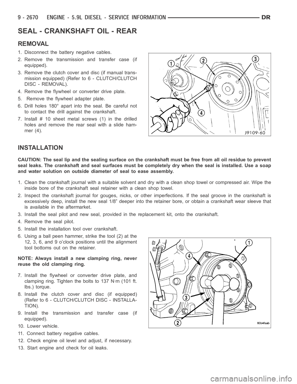
SEAL - CRANKSHAFT OIL - REAR
REMOVAL
1. Disconnect the battery negative cables.
2. Remove the transmission and transfer case (if
equipped).
3. Remove the clutch cover and disc (if manual trans-
mission equipped) (Refer to 6 - CLUTCH/CLUTCH
DISC - REMOVAL).
4. Remove the flywheel or converter drive plate.
5. Remove the flywheel adapter plate.
6. Drill holes 180° apart into the seal. Be careful not
to contact the drill against the crankshaft.
7. Install # 10 sheet metalscrews (1) in the drilled
holes and remove the rear seal with a slide ham-
mer (4).
INSTALLATION
CAUTION: The seal lip and the sealing surface on the crankshaft must be freefrom all oil residue to prevent
seal leaks. The crankshaft and seal surfaces must be completely dry when the seal is installed. Use a soap
and water solution on outside diameter of seal to ease assembly.
1. Clean the crankshaft journal with a suitable solvent and dry with a cleanshop towel or compressed air. Wipe the
inside bore of the crankshaft seal retainer with a clean shop towel.
2. Inspect the crankshaft journal forgouges, nicks, or other imperfections. If the seal groove in the crankshaft is
excessively deep, install the new seal 1/8” deeper into the retainer bore,or obtain a crankshaft wear sleeve that
is available in the aftermarket.
3. Install the seal pilot and new seal, provided in the replacement kit, onto the crankshaft.
4. Remove the seal pilot.
5. Install the installation tool over crankshaft.
6. Using a ball peen hammer, strike the tool (2) at the
12, 3, 6, and 9 o’clock positions until the alignment
tool bottoms out on the retainer.
NOTE: Always install a new clamping ring, never
reuse the old clamping ring.
7. Install the flywheel or converter drive plate, and
clamping ring. Tighten the bolts to 137 Nꞏm (101 ft.
lbs.) torque.
8. Install the clutch cover and disc (if equipped)
(Refer to 6 - CLUTCH/CLUTCH DISC - INSTALLA-
TION).
9. Install the transmission and transfer case (if
equipped).
10. Lower vehicle.
11. Connect battery negative cables.
12. Check engine oil level and adjust, if necessary.
13. Start engine and check for oil leaks.
Page 2002 of 5267
OIL
STANDARD PROCEDURE
STANDARD PROCEDURE - ENGINE OIL LEVEL
CAUTION: Do not overfill crankcase with engine
oil, oil foaming and oil pressure loss can result.
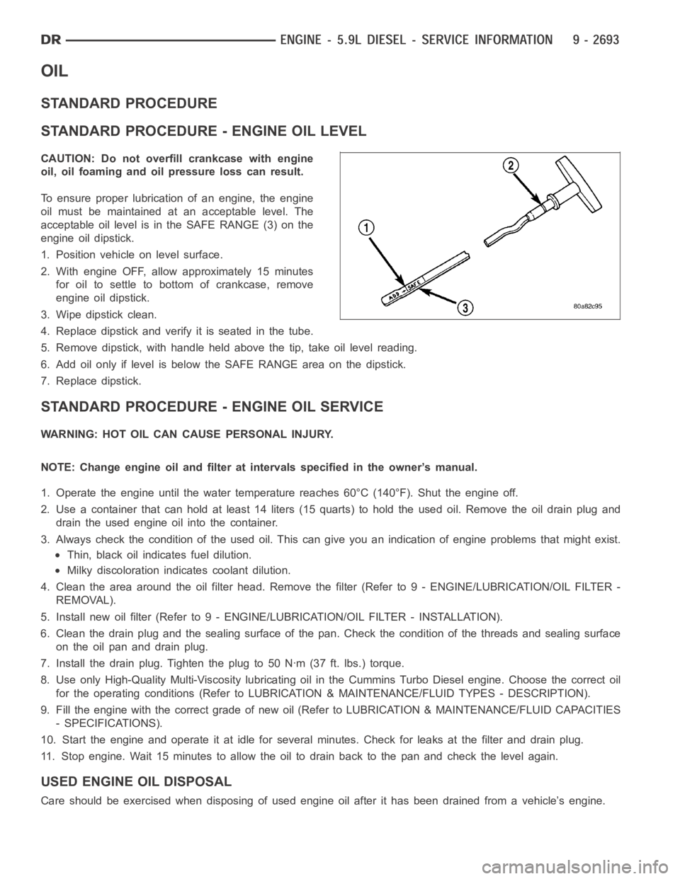
To ensure proper lubrication of an engine, the engine
oil must be maintained at an acceptable level. The
acceptable oil level is in the SAFE RANGE (3) on the
engine oil dipstick.
1. Position vehicle on level surface.
2. With engine OFF, allow approximately 15 minutes
for oil to settle to bottom of crankcase, remove
engine oil dipstick.
3. Wipe dipstick clean.
4. Replace dipstick and verify it is seated in the tube.
5. Remove dipstick, with handle held above the tip, take oil level reading.
6. Add oil only if level is below the SAFE RANGE area on the dipstick.
7. Replace dipstick.
STANDARD PROCEDURE - ENGINE OIL SERVICE
WARNING: HOT OIL CAN CAUSE PERSONAL INJURY.
NOTE: Change engine oil and filter at intervals specified in the owner’s manual.
1. Operate the engine until the water temperature reaches 60°C (140°F). Shut the engine off.
2. Use a container that can hold at least 14 liters (15 quarts) to hold the used oil. Remove the oil drain plug and
drain the used engine oil into the container.
3. Always check the condition of the used oil. This can give you an indication of engine problems that might exist.
Thin, black oil indicates fuel dilution.
Milky discoloration indicates coolant dilution.
4. Clean the area around the oil filter head. Remove the filter (Refer to 9 - ENGINE/LUBRICATION/OIL FILTER -
REMOVAL).
5. Install new oil filter (Refer to 9 - ENGINE/LUBRICATION/OIL FILTER - INSTA L L AT I O N ) .
6. Clean the drain plug and the sealing surface of the pan. Check the condition of the threads and sealing surface
on the oil pan and drain plug.
7. Install the drain plug. Tighten the plug to 50 Nꞏm (37 ft. lbs.) torque.
8. Use only High-Quality Multi-Viscosity lubricating oil in the Cummins Turbo Diesel engine. Choose the correct oil
for the operating conditions (Refer to LUBRICATION & MAINTENANCE/FLUID TYPES - DESCRIPTION).
9. Fill the engine with the correct grade of new oil (Refer to LUBRICATION & MAINTENANCE/FLUID CAPACITIES
- SPECIFICATIONS).
10. Start the engine and operate it at idle for several minutes. Check for leaks at the filter and drain plug.
11. Stop engine. Wait 15 minutes to allow the oil to drain back to the pan and check the level again.
USED ENGINE OIL DISPOSAL
Care should be exercised when disposing of used engine oil after it has beendrained from a vehicle’s engine.
Page 2005 of 5267
PA N - E N G I N E O I L
REMOVAL
1. Disconnect the battery negative cables.
2. Install engine support fixture # 8534.
3. Raise vehicle on hoist.
4. Disconnect starter cables from starter motor.
5. Remove transmission and transfer case (if equipped).
6. Remove flywheel or flexplate.
7. Remove starter motor (Refer to 8 - ELECTRICAL/STARTING/STARTER MOTOR -REMOVAL) and transmission
adapter plate assembly.
WARNING: HOT OIL CAN CAUSE PERSONAL INJURY.
8. Drain the engine oil (Refer to 9 - ENGINE/LUBRICATION/OIL - STANDARD PROCEDURE).
9. Install the oil pan drain plug if sealing surface is not damaged and tighten to 50 Nꞏm (37 ft. lbs.) torque.
10. Remove oil pan bolts, break the pan to block seal, and lower pan slightlyandremoveoilsuctiontubefasteners.
11. Remove oil pan and suction tube.
CLEANING
Remove all gasket material from the oil pan and cylinder block sealing surfaces. Extra effort may be required
around T-joint areas. Clean oil pan and flush suction tube with a suitable solvent.
INSPECTION
Inspect the oil pan, suction tube, and tube braces for cracks and damage. Replace any defective component.
Inspect the oil drain plug and drain hole threads. Inspect the oil pan sealing surface for straightness. Repair any
minor imperfections with a ball-peen hammer. Do not attempt to repair an oil pan by welding.
INSTALLATION
1. Fill the T-joint between the pan rail/gear housing and pan rail/rear seal retainer with sealant. Use MoparSilicone
Rubber Adhesive Sealant or equivalent.
2. Place suction tube in oil pan and guide them into place. Slide oil pan gasket into postion.Using a new tube to
block gasket, install and tighten the suction tube bolts by hand. Startingwith the oil pump inlet bolts, tighten the
bolts to 24 Nꞏm (18 ft. lbs.) torque. Tighten the remaining tube brace boltsto 43 Nꞏm (32 ft. lbs.) torque.
3. Starting in the center and working outward, tighten the oil pan bolts to 28Nꞏm(21ft.lbs.)torque.
4. Install the flywheel housing assembly with the starter motor attached and tighten bolts to 77 Nꞏm (57 ft. lbs.)
torque.
5. Connect starter motor cables.
NOTE: A new clamping ring must be used on early or late builds, automatic or manual. Do not reuse clamp-
ing ring.
6. Install the flywheel to crankshaft adapter. Torque to 137 Nꞏm (101 ft. lbs.).
7. Install transmission and transfer case (if equipped).
8. Lower vehicle.
9. Remove the engine support fixture # 8534.
10. Install battery negative cables.
11. Fill the crankcase with new engine oil.
12. Start engine and check for leaks. Stop engine, check oil level, and adjust, if necessary.
Page 2020 of 5267
page page
ENGINE - 8.3L - SERVICE INFORMATION
DESCRIPTION ............................. 2713
DIAGNOSIS AND TESTING
INTRODUCTION . ......................... 2714
ENGINE DIAGNOSIS - PERFORMANCE .... 2715
ENGINE DIAGNOSIS - MECHANICAL ....... 2716
CYLINDER COMPRESSION PRESSURE
TEST.................................... 2718
CYLINDER COMBUSTION PRESSURE
LEAKAGE TEST.......................... 2718
CYLINDER HEAD GASKET FAILURE
DIAGNOSIS.............................. 2719
HYDRAULIC TAPPET NOISE DIAGNOSIS . . . 2720
ENGINE OIL LEAK INSPECTION ........... 2720
STANDARD PROCEDURE
ENGINE CORE AND OIL GALLERY PLUGS . 2722
FORM-IN-PLACE GASKETS AND SEALERS . 2722
ENGINE GASKET SURFACE
PREPARATION........................... 2723
HYDROSTATIC LOCKED ENGINE .......... 2723
REMOVAL - ENGINE ASSEMBLY . . ........... 2724
INSTALLATION - ENGINE ASSEMBLY ........ 2728
SPECIFICATIONS
ENGINE ................................. 2731
TORQUE ................................. 2736
SPECIAL TOOLS
ENGINE ................................. 2738
SYSTEM-AIR INTAKE
DESCRIPTION ............................. 2741
ELEMENT-AIR CLEANER
REMOVAL ................................. 2742
INSTALLATION ............................. 2743
HOUSING-AIR CLEANER
REMOVAL ................................. 2744
INSTALLATION ............................. 2745
MOUNTS-ENGINE
REMOVAL ................................. 2746
INSTALLATION ............................. 2747
MANIFOLD-INTAKE
DIAGNOSIS AND TESTING
INTAKE MANIFOLD LEAKS ................ 2748
REMOVAL ................................. 2748
INSPECTION ............................... 2750
INSTALLATION ............................. 2751
MANIFOLD-EXHAUST
REMOVAL ................................. 2754
INSPECTION ............................... 2755
INSTALLATION ............................. 2755
HEAD(S)-CYLINDER
REMOVAL - CYLINDER HEAD(S) ............. 2757CLEANING
CLEANING AND INSPECTION............. 2758
INSTALLATION - CYLINDER HEAD(S) ........ 2758
COVER(S)-CYLINDER HEAD
REMOVAL ................................. 2760
INSTALLATION ............................. 2761
ARMS-ROCKER
REMOVAL ................................. 2762
INSTALLATION ............................. 2762
SPRINGS/SEALS-VALVE
DIAGNOSIS AND TESTING
VALVE SPRING TESTING ................. 2763
STANDARD PROCEDURE - VALVE SPRING/
SEAL SERVICE IN-CAR ................... 2763
REMOVAL ................................. 2764
INSTALLATION ............................. 2765
INTAKE/EXHAUST - VALVES/SEATS/GUIDES
STANDARD PROCEDURE - VALVE AND
VALVE SEAT - REFACING ................. 2766
INSPECTION............................... 2767
COVER-TIMING CHAIN
REMOVAL ................................. 2769
INSTALLATION ............................. 2771
TIMING CHAIN AND SPROCKETS
REMOVAL ................................. 2774
INSTALLATION ............................. 2775
LUBRICATION
DESCRIPTION ............................. 2777
OPERATION ............................... 2777
DIAGNOSIS AND TESTING
CHECKING ENGINE OIL PRESSURE ....... 2777
ENGINE OIL LEAK ........................ 2777
OIL
STANDARD PROCEDURE
CHECKING ENGINE OIL LEVEL........... 2779
ENGINE OILAND FILTER CHANGE ........ 2779
COOLER & LINES-OIL
DESCRIPTION ............................. 2781
OPERATION ............................... 2781
STANDARD PROCEDURE - OIL COOLER LINE
QUICK CONNECT FITTING DISASSEMBLY/
ASSEMBLY............................... 2781
REMOVAL ................................. 2782
INSTALLATION ............................. 2783
PAN-OIL
REMOVAL ................................. 2784
INSTALLATION ............................. 2785
PUMP-OIL
REMOVAL ................................. 2788
DISASSEMBLY . ............................ 2788
CLEANING ................................. 2789