2006 DODGE RAM SRT-10 oil level
[x] Cancel search: oil levelPage 1763 of 5267
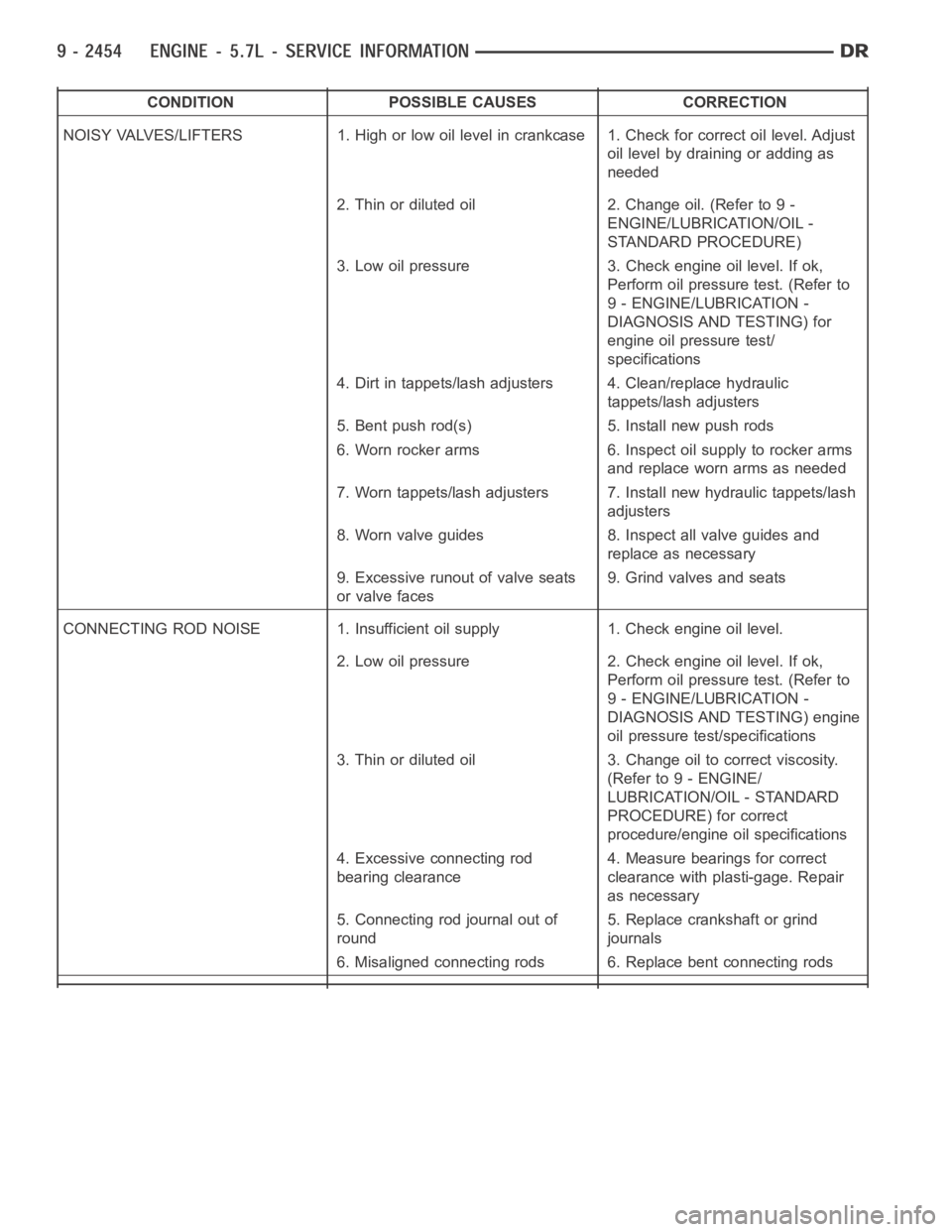
CONDITION POSSIBLE CAUSES CORRECTION
NOISY VALVES/LIFTERS 1. High or low oil level in crankcase 1. Check for correct oil level. Adjust
oil level by draining or adding as
needed
2. Thin or diluted oil 2. Change oil. (Refer to 9 -
ENGINE/LUBRICATION/OIL -
STANDARD PROCEDURE)
3. Low oil pressure 3. Check engine oil level. If ok,
Perform oil pressure test. (Refer to
9 - ENGINE/LUBRICATION -
DIAGNOSIS AND TESTING) for
engine oil pressure test/
specifications
4. Dirt in tappets/lash adjusters 4. Clean/replace hydraulic
tappets/lash adjusters
5. Bent push rod(s) 5. Install new push rods
6. Worn rocker arms 6. Inspect oil supply to rocker arms
and replace worn arms as needed
7. Worn tappets/lash adjusters 7. Install new hydraulic tappets/lash
adjusters
8. Worn valve guides 8. Inspect all valve guides and
replace as necessary
9. Excessive runout of valve seats
or valve faces9. Grind valves and seats
CONNECTING ROD NOISE 1. Insufficient oil supply 1. Check engine oil level.
2. Low oil pressure 2. Check engine oil level. If ok,
Perform oil pressure test. (Refer to
9 - ENGINE/LUBRICATION -
DIAGNOSIS AND TESTING) engine
oil pressure test/specifications
3. Thin or diluted oil 3. Change oil to correct viscosity.
(Refer to 9 - ENGINE/
LUBRICATION/OIL - STANDARD
PROCEDURE) for correct
procedure/engine oil specifications
4. Excessive connecting rod
bearing clearance4. Measure bearings for correct
clearance with plasti-gage. Repair
as necessary
5. Connecting rod journal out of
round5. Replace crankshaft or grind
journals
6. Misaligned connecting rods 6. Replace bent connecting rods
Page 1764 of 5267
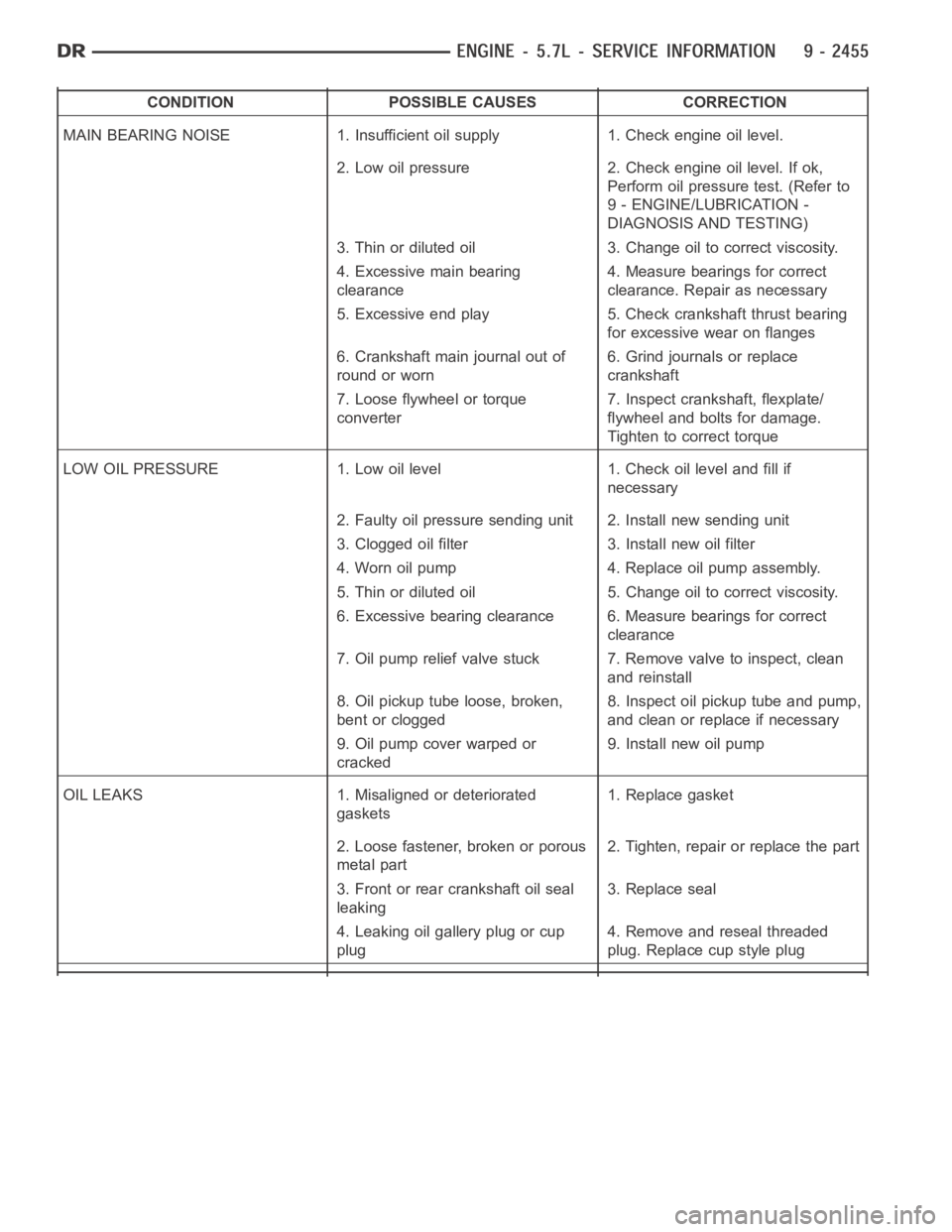
CONDITION POSSIBLE CAUSES CORRECTION
MAIN BEARING NOISE 1. Insufficient oil supply 1. Check engine oil level.
2. Low oil pressure 2. Check engine oil level. If ok,
Perform oil pressure test. (Refer to
9 - ENGINE/LUBRICATION -
DIAGNOSIS AND TESTING)
3. Thin or diluted oil 3. Change oil to correct viscosity.
4. Excessive main bearing
clearance4. Measure bearings for correct
clearance. Repair as necessary
5. Excessive end play 5. Check crankshaft thrust bearing
for excessive wear on flanges
6. Crankshaft main journal out of
round or worn6. Grind journals or replace
crankshaft
7. Loose flywheel or torque
converter7. Inspect crankshaft, flexplate/
flywheel and bolts for damage.
Tighten to correct torque
LOW OIL PRESSURE 1. Low oil level 1. Check oil level and fill if
necessary
2. Faulty oil pressure sending unit 2. Install new sending unit
3. Clogged oil filter 3. Install new oil filter
4. Worn oil pump 4. Replace oil pump assembly.
5. Thin or diluted oil 5. Change oil to correct viscosity.
6. Excessive bearing clearance 6. Measure bearings for correct
clearance
7. Oil pump relief valve stuck 7. Remove valve to inspect, clean
and reinstall
8. Oil pickup tube loose, broken,
bent or clogged8. Inspect oil pickup tube and pump,
and clean or replace if necessary
9. Oil pump cover warped or
cracked9. Install new oil pump
OIL LEAKS 1. Misaligned or deteriorated
gaskets1. Replace gasket
2. Loose fastener, broken or porous
metal part2. Tighten, repair or replace the part
3. Front or rear crankshaft oil seal
leaking3. Replace seal
4. Leaking oil gallery plug or cup
plug4. Remove and reseal threaded
plug. Replace cup style plug
Page 1824 of 5267
ENGINE BLOCK
CLEANING
Thoroughly clean the oil pan and engine block gasket surfaces.
Use compressed air to clean out:
The galley at the oil filter adaptor hole.
The front and rear oil galley holes.
The feed holes for the crankshaft main bearings.
Once the block has been completely cleaned, apply Loctite PST pipe sealantwith Teflon 592 to the threads of the
front and rear oil galley plugs. Tighten the 1/4 inch NPT plugs to 20 Nꞏm (177in. lbs.) torque. Tighten the 3/8 inch
NPT plugs to 27 Nꞏm (240 in. lbs.) torque.
INSPECTION
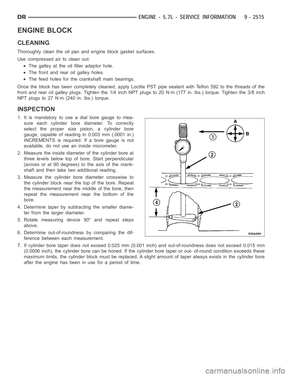
1. It is mandatory to use a dial bore gauge to mea-
sure each cylinder bore diameter. To correctly
select the proper size piston, a cylinder bore
gauge, capable of reading in 0.003 mm (.0001 in.)
INCREMENTS is required. If a bore gauge is not
available, do not use an inside micrometer.
2. Measure the inside diameter of the cylinder bore at
three levels below top of bore. Start perpendicular
(across or at 90 degrees) to the axis of the crank-
shaft and then take two additional reading.
3. Measure the cylinder bore diameter crosswise to
the cylinder block near the top of the bore. Repeat
the measurement near the middle of the bore, then
repeat the measurement near the bottom of the
bore.
4. Determine taper by subtracting the smaller diame-
ter from the larger diameter.
5. Rotate measuring device 90° and repeat steps
above.
6. Determine out-of-roundness by comparing the dif-
ference between each measurement.
7. If cylinder bore taper does not exceed 0.025 mm (0.001 inch) and out-of-roundness does not exceed 0.015 mm
(0.0006 inch), the cylinder bore can be honed. If the cylinder bore taper orout- of-round condition exceeds these
maximum limits, the cylinder block must be replaced. A slight amount of taper always exists in the cylinder bore
after the engine has been in use for a period of time.
Page 1850 of 5267
RETAINER - CRANK REAR OIL - SEAL
REMOVAL
1. Disconnect negative cable from battery.
2. Remove the transmission. (Refer to 21 - TRANS-
MISSION/TRANSAXLE/AUTOMATIC - NAG1 -
REMOVAL).
3. Remove the flexplate. (Refer to 9 - ENGINE/EN-
GINE BLOCK/FLEX PLATE - REMOVAL).
4. Remove the oil pan. (Refer to 9 - ENGINE/LUBRI-
CATION/OIL PAN - REMOVAL)
5. Remove the rear oil seal retainer mounting bolts.
6. Carefully remove the retainer from the engine
block.
INSTALLATION
1. Throughly clean all gasket resdue from the engine
block.
2. Use extream care and clean all gasket resdue from
the retainer.
3. Position the gasket onto the retainer.
4. Position the retainer onto the engine block.
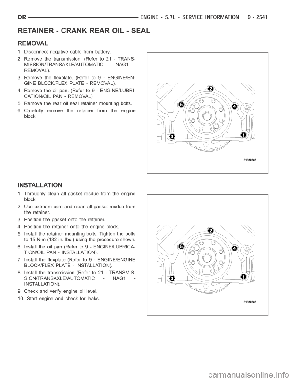
5. Install the retainer mounting bolts. Tighten the bolts
to 15 Nꞏm (132 in. lbs.) using the procedure shown.
6. Install the oil pan (Refer to 9 - ENGINE/LUBRICA-
TION/OIL PAN - INSTALLATION).
7. Install the flexplate (Refer to 9 - ENGINE/ENGINE
BLOCK/FLEX PLATE - INSTALLATION).
8. Install the transmission (Refer to 21 - TRANSMIS-
SION/TRANSAXLE/AUTOMATIC - NAG1 -
INSTALLATION).
9. Check and verify engine oil level.
10. Start engine and check for leaks.
Page 1852 of 5267
TAPPETS - HYDRAULIC ROLLER
DIAGNOSIS AND TESTING - HYDRAULIC TAPPETS
Before disassembling any part of the engine to correct tappet noise, checkthe oil pressure. If vehicle has no oil
pressure gauge, install a reliable gauge at the pressure sending-unit. The pressure should be between 207-552 kPa
(30-70 psi) at 3,000 RPM.
Check the oil level after the engine reaches normal operating temperature. Allow 5 minutes to stabilize oil level,
check dipstick. The oil level in the pan should never be above the FULL mark or below the ADD OIL mark on
dipstick. Either of these two conditions could be responsible for noisy tappets.
OIL LEVEL
HIGH
If oil level is above the FULL mark, it is possible for the connecting rods todip into the oil. With the engine running,
this condition could create foam in the oil pan. Foam in oil pan would be fed to the hydraulic tappets by the oil pump
causing them to lose length and allow valves to seat noisily.
LOW
Low oil level may allow oil pump to take in air. When air is fed to the tappets,they lose length, which allows valves
to seat noisily. Any leaks on intake side of oil pump through which air can bedrawn will create the same tappet
action. Check the lubrication system from the intake strainer to the pump cover, including the relief valve retainer
cap. When tappet noise is due to aeration, it may be intermittent or constant, and usually more than one tappet will
be noisy. When oil level and leaks have been corrected, operate the engine at fast idle. Run engine for a sufficient
time to allow all of the air inside the tappets to be bled out.
TAPPET NOISE DIAGNOSIS
1. To determine source of tappet noise, crank over engine with cylinder head covers removed.
2. Feel each valve spring or rocker arm to detect noisy tappet. The noisy tappet will cause the affected spring
and/or rocker arm to vibrate or feel rough in operation.
NOTE: Worn valve guides or cocked springs are sometimes mistaken for noisytappets. If such is the case,
noise may be dampened by applying side thrust on the valve spring. If noise is not appreciably reduced, it
can be assumed the noise is in the tappet. Inspect the rocker arm push rod sockets and push rod ends for
wear.
3. Valve tappet noise ranges from light noise to a heavy click. A light noiseis usually caused by excessive leak-
down around the unit plunger, or by the plunger partially sticking in the tappet body cylinder. The tappet should
be replaced. A heavy click is caused by a tappet check valve not seating, or by foreign particles wedged between
the plunger and the tappet body. This will cause the plunger to stick in the down position. This heavy click will be
accompanied by excessive clearance between the valve stem and rocker arm as valve closes. In either case,
tappet assembly should be removed for inspection and cleaning.
4. The valve train generates a noise very much like a light tappet noise during normal operation. Care must be
taken to ensure that tappets are making the noise. If more than one tappet seems to be noisy, it’s probably not
the tappets.
REMOVAL
1. Disconnect the negative cable from the battery.
2. Remove the air cleaner (Refer to 9 - ENGINE/AIR INTAKE SYSTEM - REMOVAL).
3. Remove intake manifold (Refer to 9 - ENGINE/MANIFOLDS/INTAKE MANIFOLD-REMOVAL).
4. Remove cylinder head cover (Refer to 9 - ENGINE/CYLINDER HEAD/CYLINDERHEAD COVER(S) -
REMOVAL).
5. Remove rocker arm assembly and push rods (Refer to 9 - ENGINE/CYLINDER HEAD/ROCKER ARM /
ADJUSTER ASSY - REMOVAL). Identify push rods to ensure installation in original location.
6. Remove the cylinder head (Refer to 9 - ENGINE/CYLINDER HEAD - REMOVAL).
Page 1859 of 5267
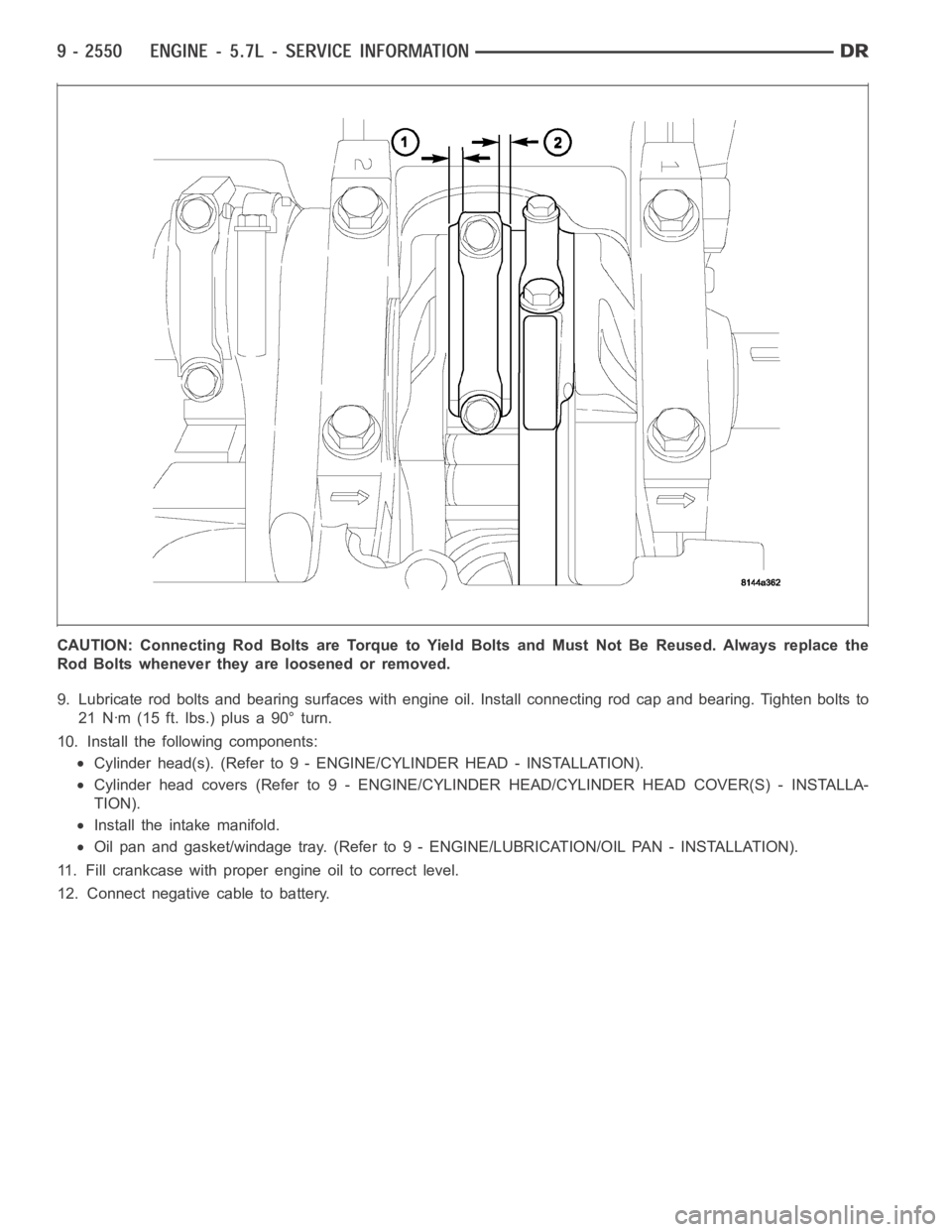
CAUTION: Connecting Rod Bolts are Torque to Yield Bolts and Must Not Be Reused. Always replace the
Rod Bolts whenever they are loosened or removed.
9. Lubricate rod bolts and bearing surfaces with engine oil. Install connecting rod cap and bearing. Tighten bolts to
21 Nꞏm (15 ft. lbs.) plus a 90° turn.
10. Install the following components:
Cylinder head(s). (Refer to 9 - ENGINE/CYLINDER HEAD - INSTALLATION).
Cylinderheadcovers(Referto9-ENGINE/CYLINDER HEAD/CYLINDER HEAD COVER(S) - INSTALLA-
TION).
Install the intake manifold.
Oil pan and gasket/windage tray. (Refer to 9 - ENGINE/LUBRICATION/OIL PAN- INSTALLATION).
11. Fill crankcase with proper engine oil to correct level.
12. Connect negative cable to battery.
Page 1877 of 5267
OIL
STANDARD PROCEDURE - ENGINE OIL SERVICE
The engine oil level indicator is located at the left hand of the engine on the 5.7L engines.
CRANKCASE OIL LEVEL INSPECTION
CAUTION: Do not overfill crankcase with engine oil, pressure loss or oil foaming can result.
Inspect engine oil level approximately every 800 kilometers (500 miles).Unless the engine has exhibited loss of oil
pressure, run the engine for about ten minutes before checking oil level. Checking engine oil level on a cold engine
is not accurate.
To ensure proper lubrication of an engine, the engine oil must be maintained at an acceptable level. The acceptable
levels are indicated between the ADD and SAFE marks on the engine oil dipstick.
1. Position vehicle on level surface.
2. With engine OFF, allow approximately five minutes for oil to settle to bottom of crankcase, remove engine oil
dipstick.
3. Wipe dipstick clean.
4. Install dipstick and verify it is seated in the tube.
5. Remove dipstick, with handle held above the tip, take oil level reading.
6. Add oil only if level is below the ADD mark on dipstick.
ENGINE OIL CHANGE
Change engine oil at mileage and time intervals described in Maintenance Schedules (Refer to LUBRICATION &
MAINTENANCE/MAINTENANCESCHEDULES - DESCRIPTION).
Run engine until achieving normal operating temperature.
1. Position the vehicle on a level surface and turn engine off.
2. Hoist and support vehicle on safety stands.
3. Remove oil fill cap.
4. Place a suitable drain pan under crankcase drain.
5. Remove drain plug from crankcase and allow oil to drain into pan. Inspectdrain plug threads for stretching or
other damage. Replace drain plug if damaged.
6. Install drain plug in crankcase. Torque to 34 Nꞏm ( 25 ft. lbs.).
7. Lower vehicle and fill crankcase with specified type and amount of engine oil described in this section.
8. Install oil fill cap.
9. Start engine and inspect for leaks.
10. Stop engine and inspect oil level.
USED ENGINE OIL DISPOSAL
Care should be exercised when disposing used engine oil after it has been drained from a vehicle engine. Refer to
the WARNING at beginning of this section.
Page 1878 of 5267
FILTER - ENGINE OIL
REMOVAL
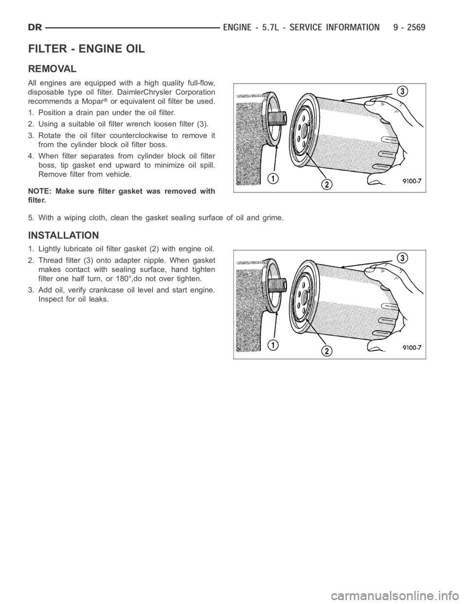
All engines are equipped with a high quality full-flow,
disposable type oil filter. DaimlerChrysler Corporation
recommends a Mopar
or equivalent oil filter be used.
1. Position a drain pan under the oil filter.
2. Using a suitable oil filter wrench loosen filter (3).
3. Rotate the oil filter counterclockwise to remove it
from the cylinder block oil filter boss.
4. When filter separates from cylinder block oil filter
boss, tip gasket end upward to minimize oil spill.
Remove filter from vehicle.
NOTE: Make sure filter gasket was removed with
filter.
5. With a wiping cloth, clean the gasket sealing surface of oil and grime.
INSTALLATION
1. Lightly lubricate oil filter gasket (2) with engine oil.
2. Thread filter (3) onto adapter nipple. When gasket
makes contact with sealing surface, hand tighten
filter one half turn, or 180°,do not over tighten.
3. Add oil, verify crankcase oil level and start engine.
Inspect for oil leaks.