Page 2321 of 5267

SENSOR - OXYGEN
DESCRIPTION
The Oxygen Sensors (O2S) are attached to, and protrude into the vehicle exhaust system. Depending on the
engine or emission package, the vehicle may use a total of either 2 or 4 sensors.
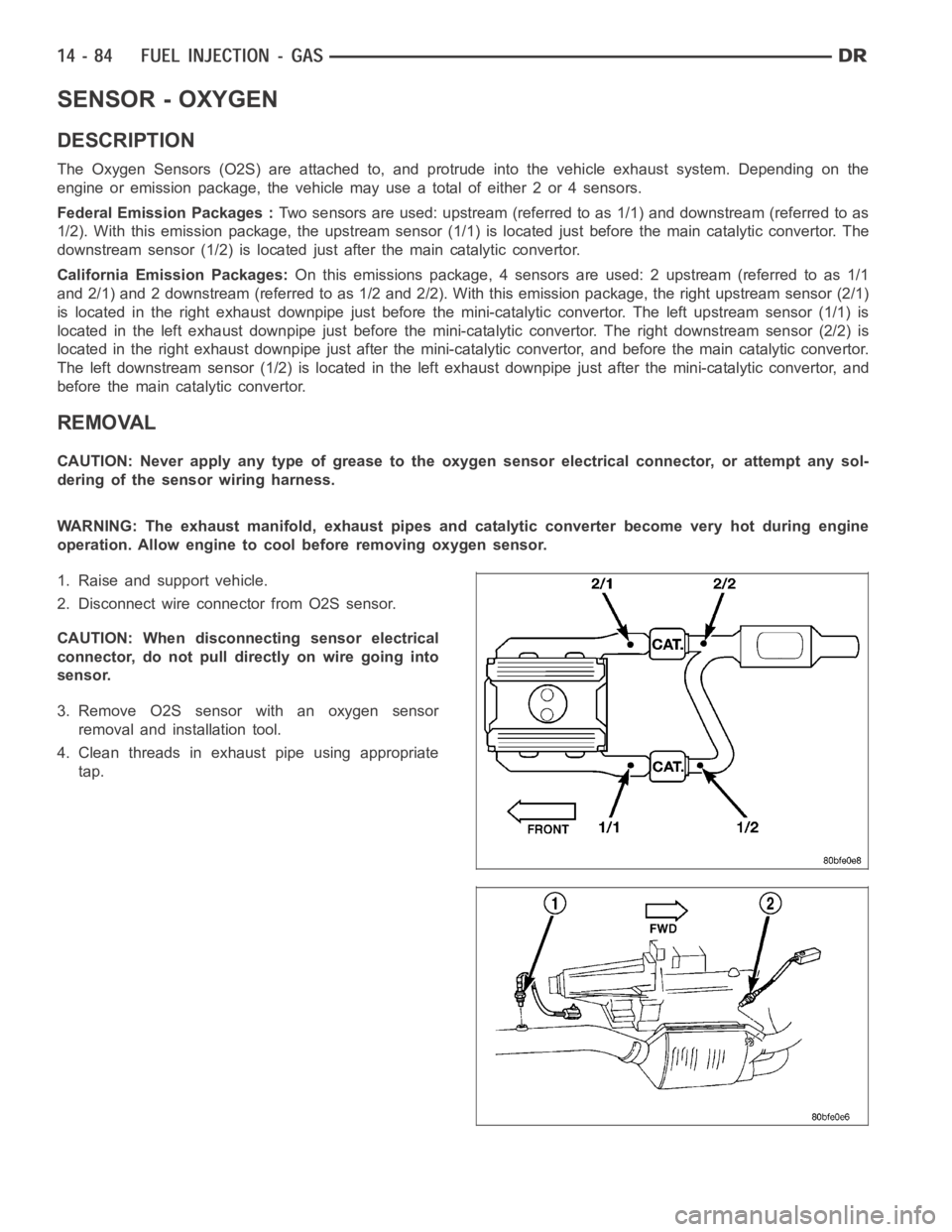
Federal Emission Packages :Two sensors are used: upstream (referred to as 1/1) and downstream (referred to as
1/2). With this emission package, the upstream sensor (1/1) is located just before the main catalytic convertor. The
downstream sensor (1/2) is located just after the main catalytic convertor.
California Emission Packages:On this emissions package, 4 sensors are used: 2 upstream (referred to as 1/1
and 2/1) and 2 downstream (referred to as 1/2 and 2/2). With this emission package, the right upstream sensor (2/1)
is located in the right exhaust downpipe just before the mini-catalytic convertor. The left upstream sensor (1/1) is
located in the left exhaust downpipe just before the mini-catalytic convertor. The right downstream sensor (2/2) is
located in the right exhaust downpipe just after the mini-catalytic convertor, and before the main catalytic convertor.
The left downstream sensor (1/2) is located in the left exhaust downpipe just after the mini-catalytic convertor, and
before the main catalytic convertor.
REMOVAL
CAUTION: Never apply any type of grease to the oxygen sensor electrical connector, or attempt any sol-
dering of the sensor wiring harness.
WARNING: The exhaust manifold, exhaust pipes and catalytic converter become very hot during engine
operation. Allow engine to cool before removing oxygen sensor.
1. Raise and support vehicle.
2. Disconnect wire connector from O2S sensor.
CAUTION: When disconnecting sensor electrical
connector, do not pull directly on wire going into
sensor.
3. Remove O2S sensor with an oxygen sensor
removal and installation tool.
4. Clean threads in exhaust pipe using appropriate
tap.
Page 2328 of 5267
5. Remove the throttle body bolts.
6. Remove the throttle body wiring clips.
7. Remove the throttle body.
Page 2331 of 5267
4. Install 4 mounting bolts. (Refer to 14 - FUEL SYS-
TEM/FUEL DELIVERY - SPECIFICATIONS)
5. Install electrical connector.
6. Install air plenum.
7.If the throttle body has been changed, the fol-
lowing procedure must be performed:
a. Disconnect negative battery cable from battery.
Leave cable disconnected for approximately 90
seconds.
b. Reconnect cable to battery.
c. Turn ignition switch ON, but do not crank
engine.
d. Leave ignition switch ON for a minimum of 10
seconds. This will allow PCM to learn throttle
body electrical parameters.
8.3L - SRT-10
1. Mount throttle body and wiring clips , tighten bolts to 12 N.m (105 in. lbs.).
2. Connect electrical connector to throttle position sensor.
3. Install the throttle cable.
4. Install the air cleaner housing, refer to Engine/Air Intake System/AirCleaner Housing.
5. Connect the negative battery cable and install the battery cover.
Page 2387 of 5267
4. Remove valve cover (Refer to 9 - ENGINE/CYLINDER HEAD/CYLINDER HEAD COVER(S) - REMOVAL).
5. Remove all 12 fuel injector wire harness nuts (1) securing integrated wiring harness to all 6 fuel injectors.
6. Remove all 12 fuel injector wire harness nuts (1)
securing integrated wiring harness to all 6 fuel
injectors.
7. An integrated fuel injector wire harness / valve
cover gasket (2) is used. After all 12 nuts (1) have
been removed, remove this integrated gasket.
Before removing gasket, disconnect engine wiring
harness at both electrical connectors (3).
8. Remove necessary high pressure fuel line connecting the necessary fuelinjector rail to high pressure connector.
Refer to Fuel Line Removal for procedures.
9. A connector retainer (nut) is used on each connector tube. Remove this nut(s) by unthreading from cylinder
head.
Page 2392 of 5267

FUEL INJECTOR RAIL
DESCRIPTION
The fuel injector rail is bolted to the top of the intake manifold.
OPERATION
The fuel rail is used as a distribution device to supply high-pressure fuelto the high-pressure fuel lines.
REMOVAL
CAUTION: Cleanliness cannot be overemphasized when handling or replacingdieselfuelsystemcompo-
nents. This especially includes the fuel injectors, high-pressure fuel lines and fuel injection pump. Very tight
tolerances are used with these parts. Dirt contamination could cause rapid part wear and possible plugging
of fuel injector nozzle tip holes. This in turn could lead to possible engine misfire. Always wash/clean any
fuel system component thoroughly before disassembly and then air dry. Capor cover any open part after
disassembly. Before assembly, examine each part for dirt, grease or othercontaminants and clean if nec-
essary. When installing new parts, lubricate them with clean engine oil orclean diesel fuel only.
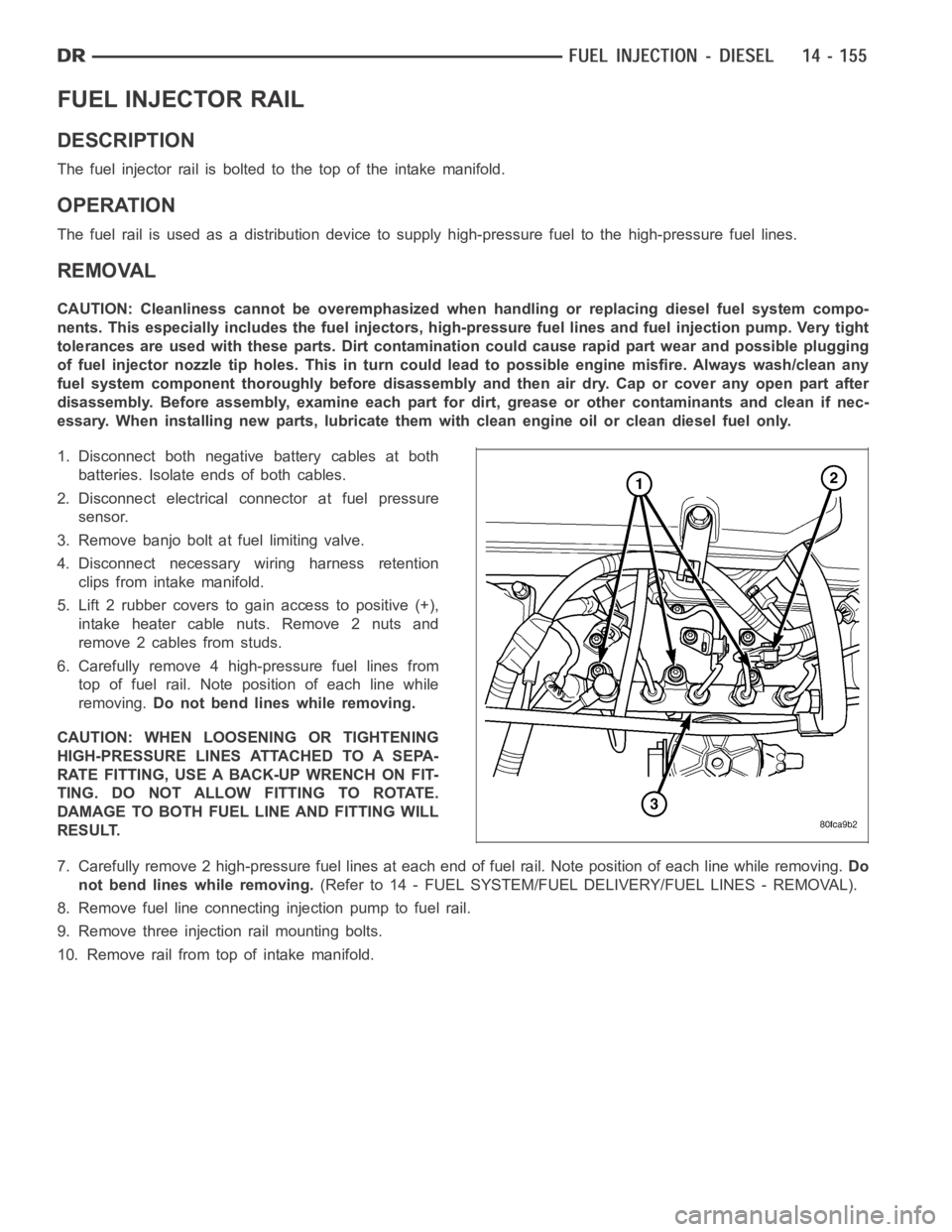
1. Disconnect both negative battery cables at both
batteries. Isolate ends of both cables.
2. Disconnect electrical connector at fuel pressure
sensor.
3. Remove banjo bolt at fuel limiting valve.
4. Disconnect necessary wiring harness retention
clips from intake manifold.
5. Lift 2 rubber covers to gain access to positive (+),
intake heater cable nuts. Remove 2 nuts and
remove 2 cables from studs.
6. Carefully remove 4 high-pressure fuel lines from
top of fuel rail. Note position of each line while
removing.Do not bend lines while removing.
CAUTION: WHEN LOOSENING OR TIGHTENING
HIGH-PRESSURE LINES ATTACHED TO A SEPA-
RATE FITTING, USE A BACK-UP WRENCH ON FIT-
TING. DO NOT ALLOW FITTING TO ROTATE.
DAMAGE TO BOTH FUEL LINE AND FITTING WILL
RESULT.
7. Carefully remove 2 high-pressure fuel lines at each end of fuel rail. Note position of each line while removing.Do
not bend lines while removing.(Refer to 14 - FUEL SYSTEM/FUEL DELIVERY/FUEL LINES - REMOVAL).
8. Remove fuel line connectinginjection pump to fuel rail.
9. Remove three injection rail mounting bolts.
10. Remove rail from top of intake manifold.
Page 2393 of 5267
INSTALLATION
1. Clean any dirt/debris from top of intake manifold
and bottom of fuel rail.
2. Position fuel rail to top of manifold and install 3
mounting bolts (1) finger tight.
3. Install all high-pressure lines to rail (Refer to 14 -
FUEL SYSTEM/FUEL DELIVERY/FUEL LINES -
REMOVAL) (Refer to 14 - FUEL SYSTEM/FUEL
DELIVERY/FUEL LINES - INSTALLATION). Torque
to 30 Nꞏm (22 ft. lbs.).
4. Tighten 3 mounting bolts at fuel rail. Torque bolts to
24 Nꞏm (18 ft. lbs.).
5. Reposition wiring harness to intake elbow and
install nut.
6. Install and tighten fuel limiting valve banjo bolt.
Copper washer against fuel limiting valve, rubber
seal against banjo bolt. Torque to 24 Nꞏm (18 ft.
lbs.).
7. Connect electrical connector to fuel pressure sen-
sor.
8. Position 2 positive (+) cables to intake heater
studs. Install 2 nuts.
9. Connect battery cables to both batteries.
10. Start engine and check for leaks.
Page 2398 of 5267
3. Lift 2 rubber covers (3) to gain access to 2 positive
(+) cable nuts.
4. Remove cable nut (6) (Fig #. ) and remove cable
from stud.
5. Remove wiring harness clips.
6. Remove engine oil dipstick tube bracket from air
inlet connection and fuel filter housing.
7. Remove four housing mounting bolts (1) and
remove heater element assembly.
Page 2400 of 5267

RELAY - INTAKE AIR HEATER
DESCRIPTION
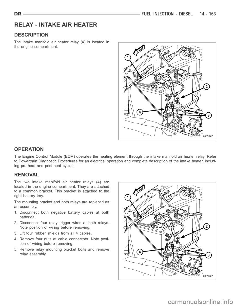
The intake manifold air heater relay (4) is located in
the engine compartment.
OPERATION
The Engine Control Module (ECM) operates the heating element through the intake manifold air heater relay. Refer
to Powertrain Diagnostic Procedures for an electrical operation and complete description of the intake heater, includ-
ing pre-heat and post-heat cycles.
REMOVAL
The two intake manifold air heater relays (4) are
located in the engine compartment. They are attached
to a common bracket. This bracket is attached to the
right battery tray.
The mounting bracket and both relays are replaced as
an assembly.
1. Disconnect both negative battery cables at both
batteries.
2. Disconnect four relay trigger wires at both relays.
Note position of wiring before removing.
3. Lift four rubber shields from all 4 cables.
4. Remove four nuts at cable connectors. Note posi-
tion of wiring before removing.
5. Remove relay mounting bracket bolts and remove
relay assembly.