Page 2413 of 5267

COLUMN
DESCRIPTION
DESCRIPTION
NOTE: The steering column on vehicles with an automatic transmission may not be equipped with an inter-
nal locking shaft that allows the ignition key cylinder to be locked with the key. Alternative methods of lock-
ing the steering wheel for service will have to be used.
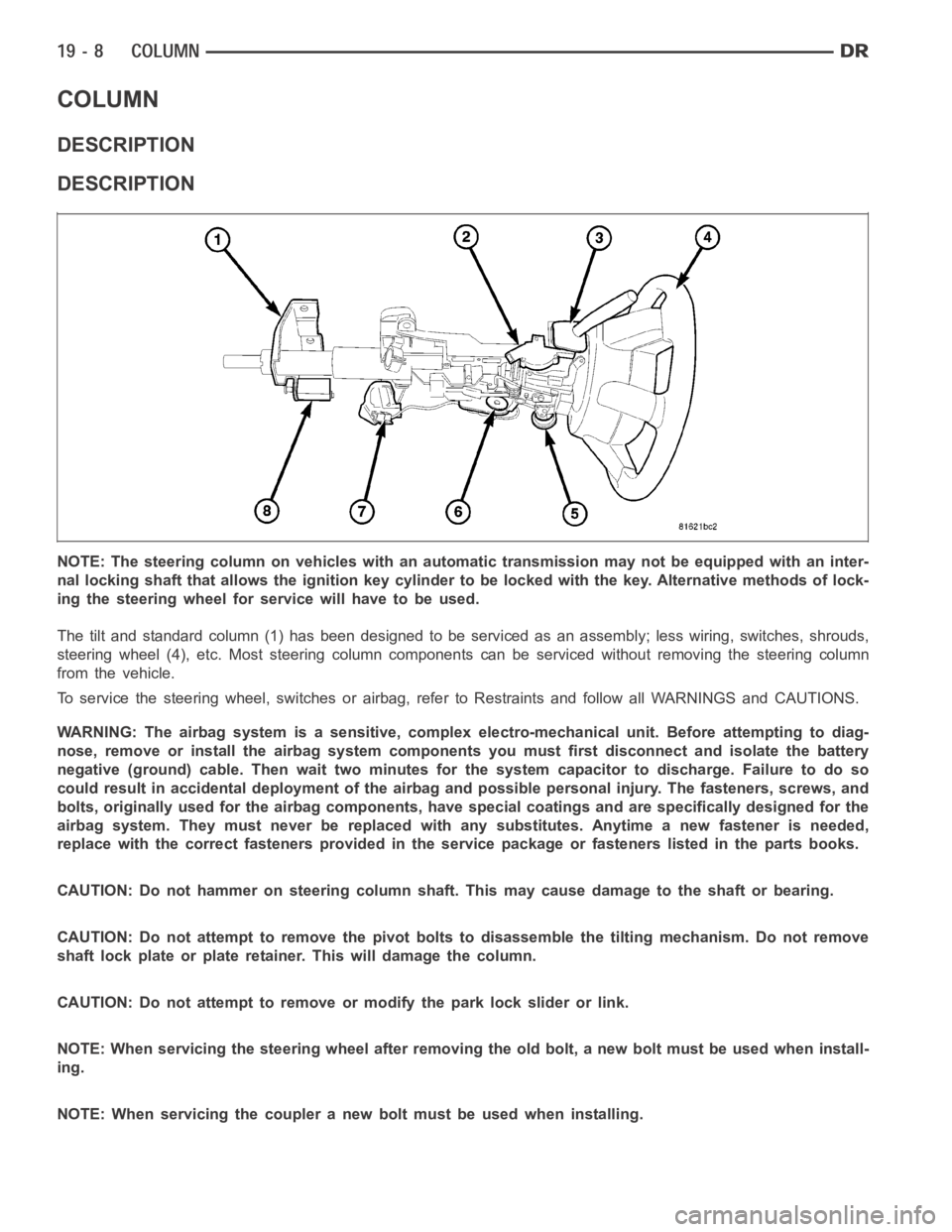
The tilt and standard column (1) has been designed to be serviced as an assembly; less wiring, switches, shrouds,
steering wheel (4), etc. Most steering column components can be serviced without removing the steering column
from the vehicle.
To service the steering wheel, switches or airbag, refer to Restraints andfollow all WARNINGS and CAUTIONS.
WARNING: The airbag system is a sensitive, complex electro-mechanical unit. Before attempting to diag-
nose, remove or install the airbag system components you must first disconnect and isolate the battery
negative (ground) cable. Then wait two minutes for the system capacitor todischarge. Failure to do so
could result in accidental deployment of the airbag and possible personalinjury. The fasteners, screws, and
bolts, originally used for the airbag components, have special coatings and are specifically designed for the
airbag system. They must never be replaced with any substitutes. Anytime anew fastener is needed,
replace with the correct fasteners provided in the service package or fasteners listed in the parts books.
CAUTION: Do not hammer on steering column shaft. This may cause damage to the shaft or bearing.
CAUTION: Do not attempt to remove the pivot bolts to disassemble the tilting mechanism. Do not remove
shaft lock plate or plate retainer. This will damage the column.
CAUTION: Do not attempt to remove or modify the park lock slider or link.
NOTE: When servicing the steering wheel after removing the old bolt, a new bolt must be used when install-
ing.
NOTE: When servicing the coupler a new bolt must be used when installing.
Page 2416 of 5267
8. Remove the clock spring, (Refer to 8 - ELECTRI-
CAL/RESTRAINTS/CLOCKSPRING - REMOVAL).
9. Disconnect the wiring harness (8) to the column.
10. Remove the shift cable (5) from the column shift
lever actuator (4) (Refer to 21 - TRANSMISSION/
TRANSAXLE/AUTOMATIC - 32RH/GEAR SHIFT
CABLE - REMOVAL).
11. Release the shift cable (5) from the column
bracket (7) and remove it from the bracket.
12. Remove the upper steering shaft coupler bolt (2).
13. Separate the shaft from the coupler (3).
14. Remove the brake light switch (2) and discard
(Refer to 8 - ELECTRICAL/LAMPS/LIGHTING -
EXTERIOR/BRAKE LAMP SWITCH - REMOVAL).
15. Remove the four steering column mounting nuts
(1 & 3).
Page 2418 of 5267
7. Install the shifter cable (5). (Refer to 21 - TRANS-
MISSION/TRANSAXLE/AUTOMATIC - 32RH/GEAR
SHIFT CABLE - INSTALLATION)
8. Connect the wiring harness (8) to the column.
9. Install the clockspring (Refer to 8 - ELECTRICAL/
RESTRAINTS/CLOCKSPRING - REMOVAL).
10. Install the shrouds (1&2).
11. Align the spline on the wheel hub to shaft.
12. Then install the steering wheel and install anewbolt. Tighten the bolt to 61 Nꞏm (45 ft. lbs.).
13. Install the airbag (Refer to 8 - ELECTRICAL/RESTRAINTS/DRIVER AIRBAG- INSTALLATION).
14. Install the tilt lever knob (2).
Page 2422 of 5267
7. Disconnect the electrical connector at rear of igni-
tion switch (4).
8. Remove ignition switch mounting screws (2).
9. Using a small screwdriver, push on locking tab (3)
and remove switch (1) from steering column.
INSTALLATION
The ignition key must be in the key cylinder for cylinder installation. Thekey cylinder must be removed first before
installing ignition switch.
1. Before installing ignitionswitch (1), rotate the slot
in the switch to the ON position.
2. Position switch (1) to column and install the mount-
ing screws (2). Tighten screw to 3 Nꞏm (26 in. lbs.).
3. Connect the electrical connector to rear of the igni-
tion switch (4). Make sure that locking tabs are fully
seated into wiring connector.
Page 2424 of 5267
IGNITION SWITCH - SRT10
REMOVAL - SRT10
The ignition switch (1) attaches to the lock cylinder
housing (2) on the end opposite the lock cylinder. For
ignition switch terminal and circuit identification, refer
to the Wiring Diagrams sections.
1. Disconnect negative cable from battery.
2. Place key cylinder in RUN position. Through the
hole in the lower shroud (2), depress lock cylinder
retaining tab and remove key cylinder.
3. Remove upper and lower shrouds (3) from steering
column.
4. Disconnect electrical connectors from ignition
switch (1).
Page 2427 of 5267

KEY-IN IGNITION SWITCH
DESCRIPTION
The key-in ignition switch is integral to the ignition switch, which is mounted on the left side of the steering column.
ItclosesapathtogroundfortheCentralTimerModule(CTM)whentheignition key is inserted in the ignition key
cylinder and the driver door ajar switch is closed (driver door is open). The key-in ignition switch opens the ground
path when the key is removed from the ignition key cylinder. The ground pathis also opened when the driver door
ajar switch is open (driver door is closed).
The key-in ignition switch cannot be repaired and, if faulty or damaged, the entire ignition switch must be replaced,
(Refer to 19 - STEERING/COLUMN/IGNITION SWITCH - REMOVAL).
DIAGNOSIS AND TESTING
IGNITION SWITCH AND KEY LOCK CYLINDER
ELECTRICAL DIAGNOSIS
For ignition switch electrical schematics, refer to Ignition Switch in the appropriate section of Electrical Wiring Dia-
grams.
MECHANICAL DIAGNOSIS (KEY DIFFICULT TO ROTATE)
(Refer to 19 - STEERING/COLUMN/IGNITION SWITCH - DIAGNOSIS AND TESTING).
Page 2726 of 5267

P0122-TPS/APP CIRCUIT LOW
For a complete wiring diagramRefer to Section 8W.
When Monitored:
Continuously with the ignition on and engine running.
Set Condition:
This DTC will set if the monitored TPS voltage drops below .078 volts for theperiod of 0.48 seconds.
Possible Causes
RELATED TPS ENGINE DTCS PRESENT
POWERTRAIN CONTROL MODULE
Always perform the Pre-Diagnostic Troubleshooting procedure before proceeding. (Refer to 21 - TRANSMIS-
SION/TRANSAXLE/AUTOMATIC - 42RLE - STANDARD PROCEDURE)
Theory of Operation
The powertrain controller receives the throttle position signal from theThrottle Position Sensor (TPS). The controller
provides the TPS with a 5 volt pull up and a sensor ground. The signal is checked for being out of range as well
as for intermittent operation (excessive signal changes). The engine controller transmits the throttle value onto the
Bus. Most engine controllers will calculate the throttle value if the throttle signal is lost. If an error is detected by the
transmission controller and the throttle value is available on the Bus, the Bus value will be used, normal operation
will continue, and a TPS code will be set. If an error is detected and the throttle value is not available on the Bus,
normal operation will be discontinued, a TPS DTC will be set, and the MIL will be turned on after 5 minutes of
calculated operation.
Diagnostic Test
1.DETERMINING IF RELATED ENGINE TPS DTCS ARE PRESENT
With the scan tool, check Engine DTCs, including pending DTCs and one trip failures.
Are there any Engine TPS DTCs present?
Ye s>>
Refer to the Driveability category and perform the appropriate diagnostic procedure.
Perform 42RLE TRANSMISSION VERIFICATION TEST - VER 1. (Refer to 21 - TRANSMISSION/
TRANSAXLE/AUTOMATIC - 42RLE - STANDARD PROCEDURE)
No>>
Go To 2
2.CHECK IF THE DTC IS CURRENT
With the scan tool, record the DTC EVENT DATA to help identify the conditionsinwhichtheDTCwasset.
With the scan tool, erase Transmission DTCs.
NOTE: To erase EVENT DATA information, a BATTERY DISCONNECT must be performed. Performing a BAT-
TERY DISCONNECT will reset all learned Transmission values to controllerdefaults which may lead to
erratic shift schedules.
Drive the vehicle and try to duplicate the conditions in which the DTC was reported by the DTC EVENT DATA.
With the scan tool, read Transmission DTCs.
Does this DTC reset?
Ye s>>
Using the schematics as a guide, check the Powertrain Control Module (PCM)terminals for corrosion,
damage, or terminal push out. Pay particular attention to all power and ground circuits. Check for Ser-
vice Information Tune-ups or Service Bulletins for any possible causes that may apply. If no problems
are found, replace the PCM per the Service Information. With the scan tool,perform QUICK LEARN.
Perform 42RLE TRANSMISSION VERIFICATION TEST - VER 1. (Refer to 21 - TRANSMISSION/
TRANSAXLE/AUTOMATIC - 42RLE - STANDARD PROCEDURE)
No>>
Go To 3
Page 2727 of 5267
3.INTERMITTENT WIRING AND CONNECTORS
The conditions necessary to set this DTC are not present at this time.
Using the schematics as a guide, inspect the wiring and connectors specifictothiscircuit.
Wiggle the wires while checking for shorted and open circuits.
Pay particular attention to the TPS signal and sensor ground circuits.
With the scan tool, check the DTC EVENT DATA to help identify the conditionsin which the DTC was set.
Check for any Service Information Tune-ups or Service Bulletins for any possible causes that may apply.
Were there any problems found?
Ye s>>
Repair as necessary.
Perform 42RLE TRANSMISSION VERIFICATION TEST - VER 1. (Refer to 21 - TRANSMISSION/
TRANSAXLE/AUTOMATIC - 42RLE - STANDARD PROCEDURE)
No>>
Te s t C o m p l e t e .