2006 DODGE RAM SRT-10 wiring
[x] Cancel search: wiringPage 1920 of 5267
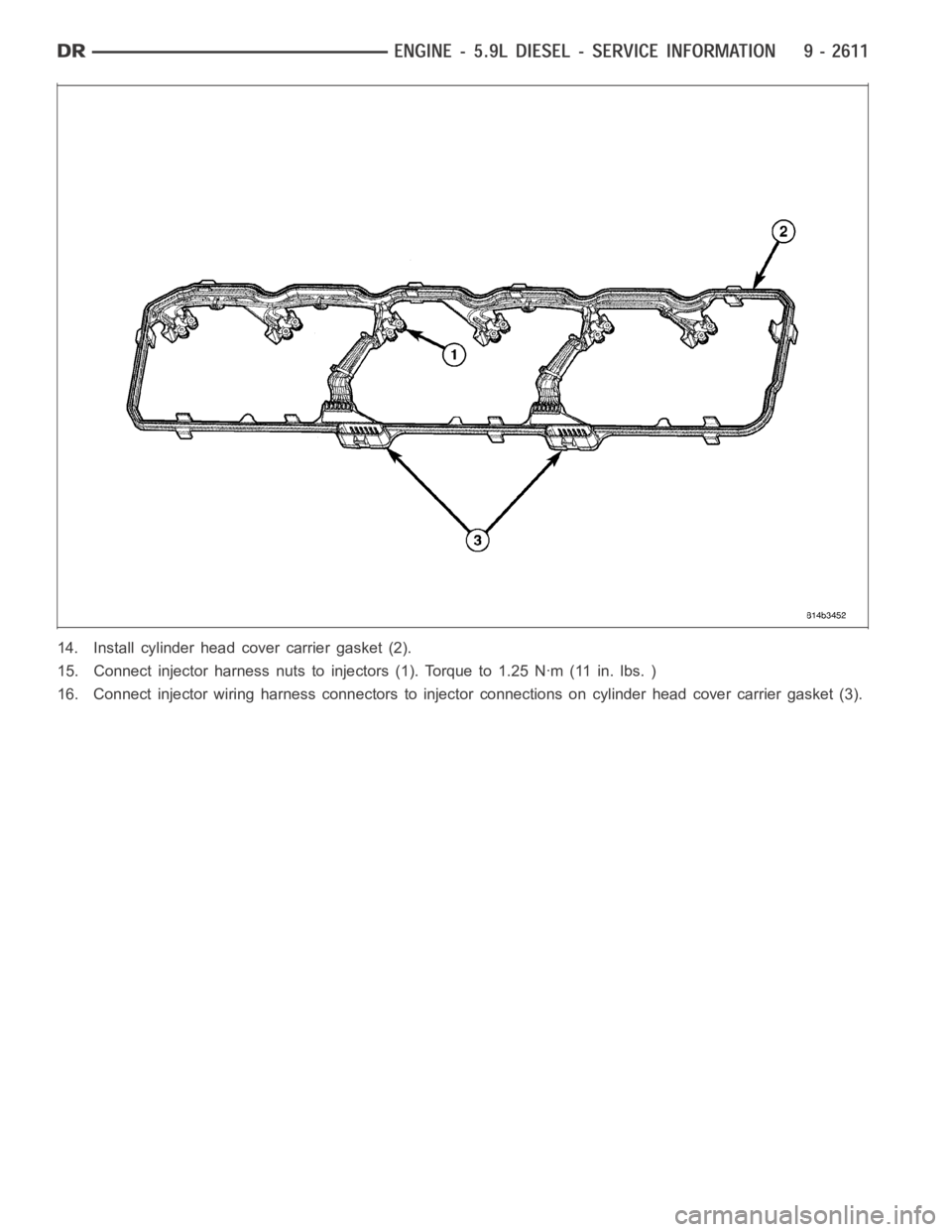
14. Install cylinder head cover carrier gasket (2).
15. Connect injector harness nuts to injectors (1). Torque to 1.25 Nꞏm (11 in. lbs. )
16. Connect injector wiring harness connectors to injector connections on cylinder head cover carrier gasket (3).
Page 2011 of 5267
MANIFOLD - INTAKE
REMOVAL
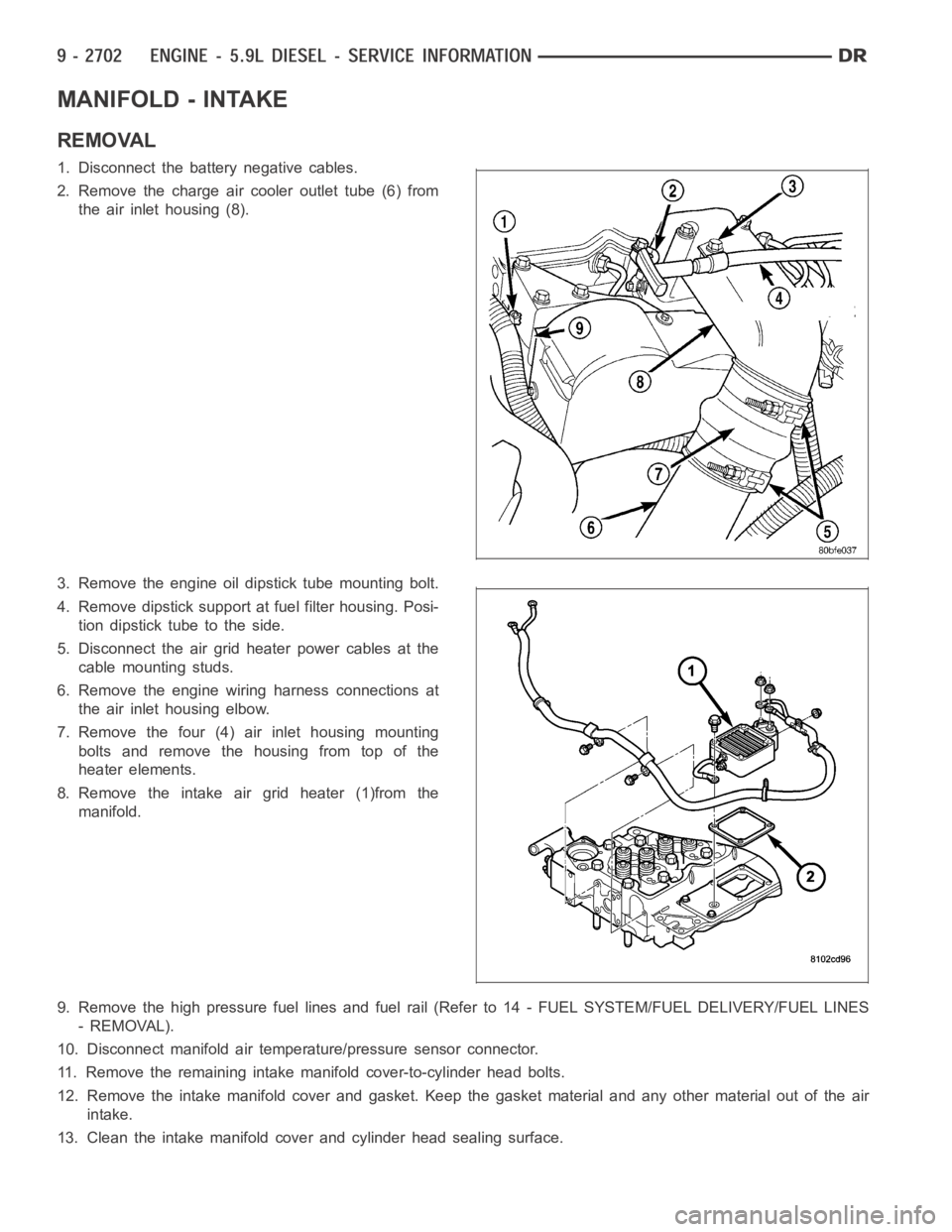
1. Disconnect the battery negative cables.
2. Remove the charge air cooler outlet tube (6) from
the air inlet housing (8).
3. Remove the engine oil dipstick tube mounting bolt.
4. Remove dipstick support at fuel filter housing. Posi-
tion dipstick tube to the side.
5. Disconnect the air grid heater power cables at the
cable mounting studs.
6. Remove the engine wiring harness connections at
the air inlet housing elbow.
7. Remove the four (4) air inlet housing mounting
bolts and remove the housing from top of the
heater elements.
8. Remove the intake air grid heater (1)from the
manifold.
9. Remove the high pressure fuel lines and fuel rail (Refer to 14 - FUEL SYSTEM/FUEL DELIVERY/FUEL LINES
- REMOVAL).
10. Disconnect manifold air temperature/pressure sensor connector.
11. Remove the remaining intake manifold cover-to-cylinder head bolts.
12. Remove the intake manifold cover and gasket. Keep the gasket material and any other material out of the air
intake.
13. Clean the intake manifold cover and cylinder head sealing surface.
Page 2080 of 5267
25. Remove A/C compressor mounting bolts. Reposi-
tion A/C compressor.Do notdisconnect A/C lines.
26. Disconnect the power steering line support
bracket at the radiator.
27. Lower the vehicle.
28. Remove the upper radiator hose and coolant
recovery container.
29. Remove the cooling fan module (Refer to 7 -
COOLING/ENGINE/RADIATOR FAN -
REMOVAL).
30. Remove the upper idler pulley.
31. Remove power steering pump mounting bolts.
Reposition power steering pump aside.Do not
disconnect power steering lines.
32. Remove the generator (Refer to 8 - ELECTRI-
CAL/CHARGING/GENERATOR - REMOVAL).
33. Disconnect the heater hose at the timing cover.
34. Disconnect the ground wire at the thermostat
housing.
NOTE: Do Not remove the camshaft position sensor from the timing cover.
35. Disconnect the camshaft sensor wiring harness connector.
36. Disconnect engine coolant temperature (ECT) sensor connector.
37. Remove crankshaft pulley and damper (Refer to 9 - ENGINE/ENGINE BLOCK/VIBRATION DAMPER -
REMOVAL).
38. Remove the timing cover.
INSTALLATION
CAUTION: Do not use a metal scraper to clean alu-
minum sealing surfaces, as damage to surfaces
may occur. Use only a plastic scraper and Mopar
Brake Parts Cleaner or the equivalent.
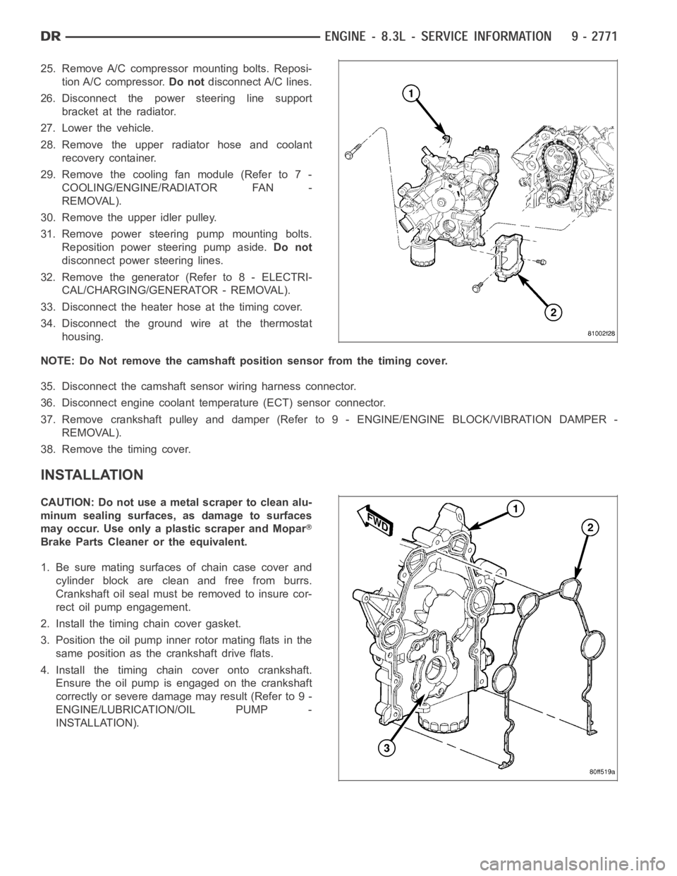
1. Be sure mating surfaces of chain case cover and
cylinder block are clean and free from burrs.
Crankshaft oil seal must be removed to insure cor-
rect oil pump engagement.
2. Install the timing chain cover gasket.
3. Position the oil pump inner rotor mating flats in the
same position as the crankshaft drive flats.
4. Install the timing chain cover onto crankshaft.
Ensure the oil pump is engaged on the crankshaft
correctly or severe damage may result (Refer to 9 -
ENGINE/LUBRICATION/OIL PUMP -
INSTALLATION).
Page 2081 of 5267

5. Hand start bolts No.1 and No.2.
6. Loosely install A/C compressor mounting bracket.
7. Hand start remaining timing chain cover bolts.
8. Torque timing chain cover bolts in the sequence
showninto23Nꞏm(200in.lbs.).
9. Torque A/C compressor mounting bracket bolts to
23 Nꞏm (200 in. lbs.).
10. Install crankshaft oil seal (Refer to 9 - ENGINE/
ENGINE BLOCK/CRANKSHAFT OIL SEAL -
FRONT - INSTALLATION).
11. Raise vehicle on hoist.
12. Install oil pump pick up tube using anewo-ring.
Torque 1/4–20 bolt to 11 Nꞏm (95 in. lbs.). Torque
5/16–18 nuts to 23 Nꞏm (200 in. lbs.).
13. Support the engine with a jack stand.
14. Install oil pan and drain plug (Refer to 9 -
ENGINE/LUBRICATION/OIL PAN - INSTALLA-
TION).
15. Remove the jackstand.
16. Tighten the engine mount to frame nuts to 102
Nꞏm (75 ft.lbs.).
17. Connect the oil cooler coolant hose to the timing
cover.
18. Connect the oil cooler line (Refer to 9 - ENGINE/
LUBRICATION/OIL COOLER & LINES - STAN-
DARD PROCEDURE).
19. Install the lower radiator hose.
20. Install the flywheel inspection cover.
21. Install the front frame cross member (Refer to 13
- FRAME & BUMPERS/FRAME/FRONT CROSS-
MEMBER - INSTALLATION).
22. Lower vehicle.
23. Position the compressor and install A/C compressor mounting bolts. Torque bolts to 23 Nꞏm (200 in. lbs.).
24. Connect heater hose at timing cover.
25. Install crankshaft damper and pulley (Refer to 9 - ENGINE/ENGINE BLOCK/VIBRATION DAMPER - INSTAL-
LATION).
26. Install generator. Connect electrical connectors.
27. Install the idler pulley.
28. Connect the camshaft position sensor wiring harness connector.
29. Connect engine coolant temperature (ECT) sensor wiring harness connector.
30. Install power steering pump mounting bolts.
31. Install accessory drive belt (Refer to 7 - COOLING/ACCESSORY DRIVE/DRIVE BELTS - INSTALLATION).
32. Install the radiator fan assembly (Refer to 7 - COOLING/ENGINE/RADIATOR FAN - INSTALLATION).
Page 2145 of 5267
8.3L ENGINE
1. Raise and support vehicle.
2. Saturate the bolts and nuts with heat valve lubri-
cant. Allow 5 minutes for penetration.
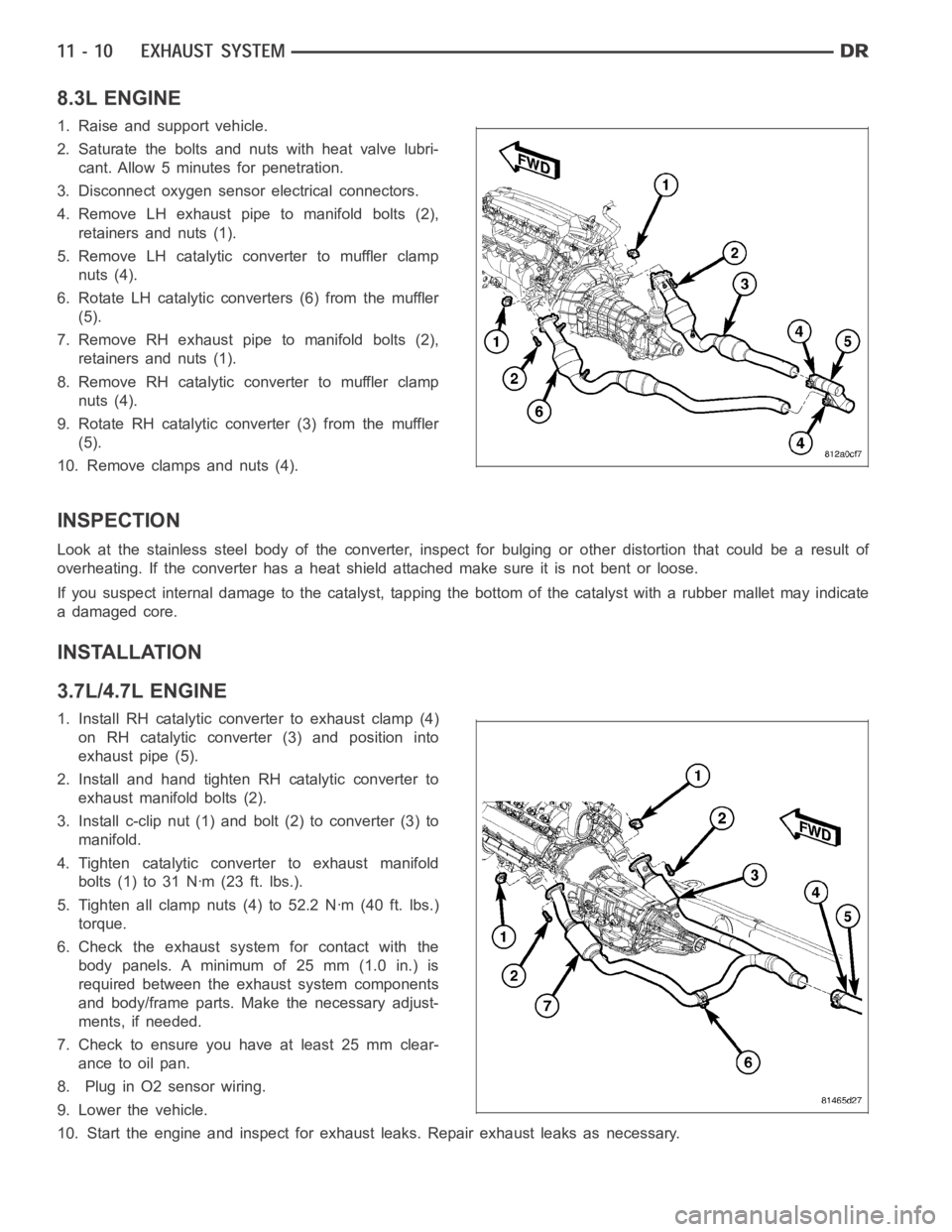
3. Disconnect oxygen sensor electrical connectors.
4. Remove LH exhaust pipe to manifold bolts (2),
retainers and nuts (1).
5. Remove LH catalytic converter to muffler clamp
nuts (4).
6. Rotate LH catalytic converters (6) from the muffler
(5).
7. Remove RH exhaust pipe to manifold bolts (2),
retainers and nuts (1).
8. Remove RH catalytic converter to muffler clamp
nuts (4).
9. Rotate RH catalytic converter (3) from the muffler
(5).
10. Remove clamps and nuts (4).
INSPECTION
Look at the stainless steel body of the converter, inspect for bulging or other distortion that could be a result of
overheating. If the converter has a heat shield attached make sure it is notbent or loose.
If you suspect internal damage to the catalyst, tapping the bottom of the catalyst with a rubber mallet may indicate
a damaged core.
INSTALLATION
3.7L/4.7L ENGINE
1. Install RH catalytic converter to exhaust clamp (4)
on RH catalytic converter (3) and position into
exhaust pipe (5).
2. Install and hand tighten RH catalytic converter to
exhaust manifold bolts (2).
3. Install c-clip nut (1) and bolt (2) to converter (3) to
manifold.
4. Tighten catalytic converter to exhaust manifold
bolts(1)to31Nꞏm(23ft.lbs.).
5. Tighten all clamp nuts (4) to 52.2 Nꞏm (40 ft. lbs.)
torque.
6. Check the exhaust system for contact with the
body panels. A minimum of 25 mm (1.0 in.) is
required between the exhaust system components
and body/frame parts. Make the necessary adjust-
ments, if needed.
7. Check to ensure you have at least 25 mm clear-
ance to oil pan.
8. Plug in O2 sensor wiring.
9. Lower the vehicle.
10. Start the engine and inspect for exhaust leaks. Repair exhaust leaks asnecessary.
Page 2204 of 5267
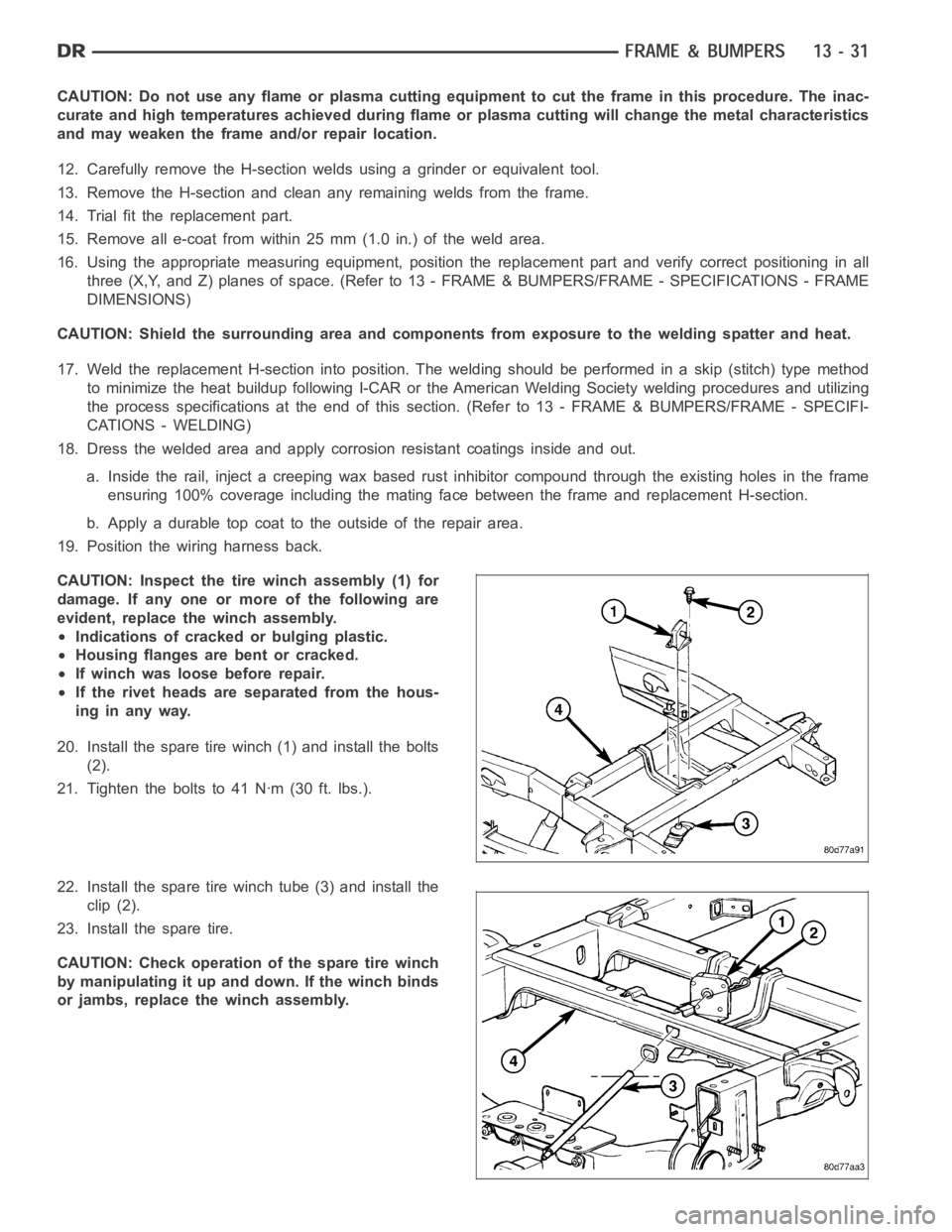
CAUTION: Do not use any flame or plasma cutting equipment to cut the frame inthis procedure. The inac-
curate and high temperatures achieved during flame or plasma cutting willchange the metal characteristics
and may weaken the frame and/or repair location.
12. Carefully remove the H-section welds using a grinder or equivalent tool.
13. Remove the H-section and clean any remaining welds from the frame.
14. Trial fit the replacement part.
15. Remove all e-coat from within 25 mm (1.0 in.) of the weld area.
16. Using the appropriate measuring equipment, position the replacementpart and verify correct positioning in all
three (X,Y, and Z) planes of space. (Refer to 13 - FRAME & BUMPERS/FRAME - SPECIFICATIONS - FRAME
DIMENSIONS)
CAUTION: Shield the surrounding area and components from exposure to the welding spatter and heat.
17. Weld the replacement H-section into position. The welding should be performedinaskip(stitch)typemethod
to minimize the heat buildup followingI-CAR or the American Welding Society welding procedures and utilizing
the process specifications at the end of this section. (Refer to 13 - FRAME &BUMPERS/FRAME - SPECIFI-
CATIONS - WELDING)
18. Dress the welded area and apply corrosion resistant coatings inside and out.
a. Inside the rail, inject a creeping wax based rust inhibitor compound through the existing holes in the frame
ensuring 100% coverage including the mating face between the frame and replacement H-section.
b. Apply a durable top coat to the outside of the repair area.
19. Position the wiring harness back.
CAUTION: Inspect the tire winch assembly (1) for
damage. If any one or more of the following are
evident, replace the winch assembly.
Indications of cracked or bulging plastic.
Housing flanges are bent or cracked.
If winch was loose before repair.
If the rivet heads are separated from the hous-
inginanyway.
20. Install the spare tire winch (1) and install the bolts
(2).
21. Tightentheboltsto41Nꞏm(30ft.lbs.).
22. Install the spare tire winch tube (3) and install the
clip (2).
23. Install the spare tire.
CAUTION: Check operation of the spare tire winch
by manipulating it up and down. If the winch binds
or jambs, replace the winch assembly.
Page 2247 of 5267
SENSOR - FUEL LEVEL SENDING UNIT
DESCRIPTION
The fuel gauge sending unit (fuel level sensor) is attached to the side of the fuel pump module. The sending unit
consists of a float, an arm, and a variable resistor track (card).
OPERATION
The fuel pump module has 4 different circuits (wires). Two of these circuits are used for the fuel gauge sending unit
for fuel gauge operation, and for certain OBD II emission requirements. The other 2 wires are used for electric fuel
pump operation.
For Fuel Gauge Operation:A constant current source is supplied to the resistor track on the fuel gauge sending
unit. This is fed directly from the Powertrain Control Module (PCM).NOTE: For diagnostic purposes, this 12V
power source can only be verified with the circuit opened (fuel pump moduleelectrical connector
unplugged). With the connectors plugged, output voltages will vary from about 0.6 volts at FULL, to about
8.6 volts at EMPTY (about 8.6 volts at EMPTY for Jeep models, and about 7.0 volts at EMPTY for Dodge
Truck models).The resistor track is used to vary the voltage (resistance) depending on fuel tank float level. As fuel
level increases, the float and arm move up, which decreases voltage. As fuel level decreases, the float and arm
move down, which increases voltage. The varied voltage signal is returnedback to the PCM through the sensor
return circuit.
Both of the electrical circuits between the fuel gauge sending unit and thePCM are hard-wired (not multi-plexed).
After the voltage signal is sent from the resistor track, and back to the PCM, the PCM will interpret the resistance
(voltage) data and send a message across the multi-plex bus circuits to theinstrument panel cluster. Here it is
translated into the appropriate fuel gauge level reading. Refer to Instrument Panel for additional information.
For OBD II Emission Monitor Requirements:The PCM will monitor the voltage output sent from the resistor track
on the sending unit to indicate fuel level. The purpose of this feature is toprevent the OBD II system from recording/
setting false misfire and fuel systemmonitor diagnostic trouble codes. The feature is activated if the fuel level in the
tank is less than approximately 15 percent of its rated capacity. If equipped with a Leak Detection Pump (EVAP
system monitor), this feature will also be activated if the fuel level in the tank is more than approximately 85 percent
of its rated capacity.
REMOVAL
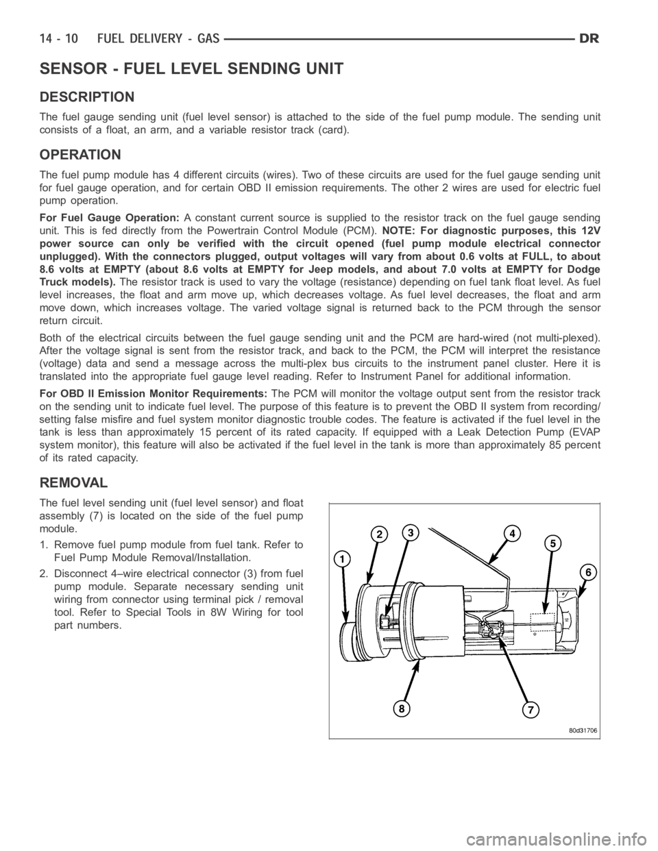
The fuel level sending unit (fuel level sensor) and float
assembly (7) is located on the side of the fuel pump
module.
1. Remove fuel pump module from fuel tank. Refer to
Fuel Pump Module Removal/Installation.
2. Disconnect 4–wire electrical connector (3) from fuel
pump module. Separate necessary sending unit
wiring from connector using terminal pick / removal
tool. Refer to Special Tools in 8W Wiring for tool
part numbers.
Page 2248 of 5267
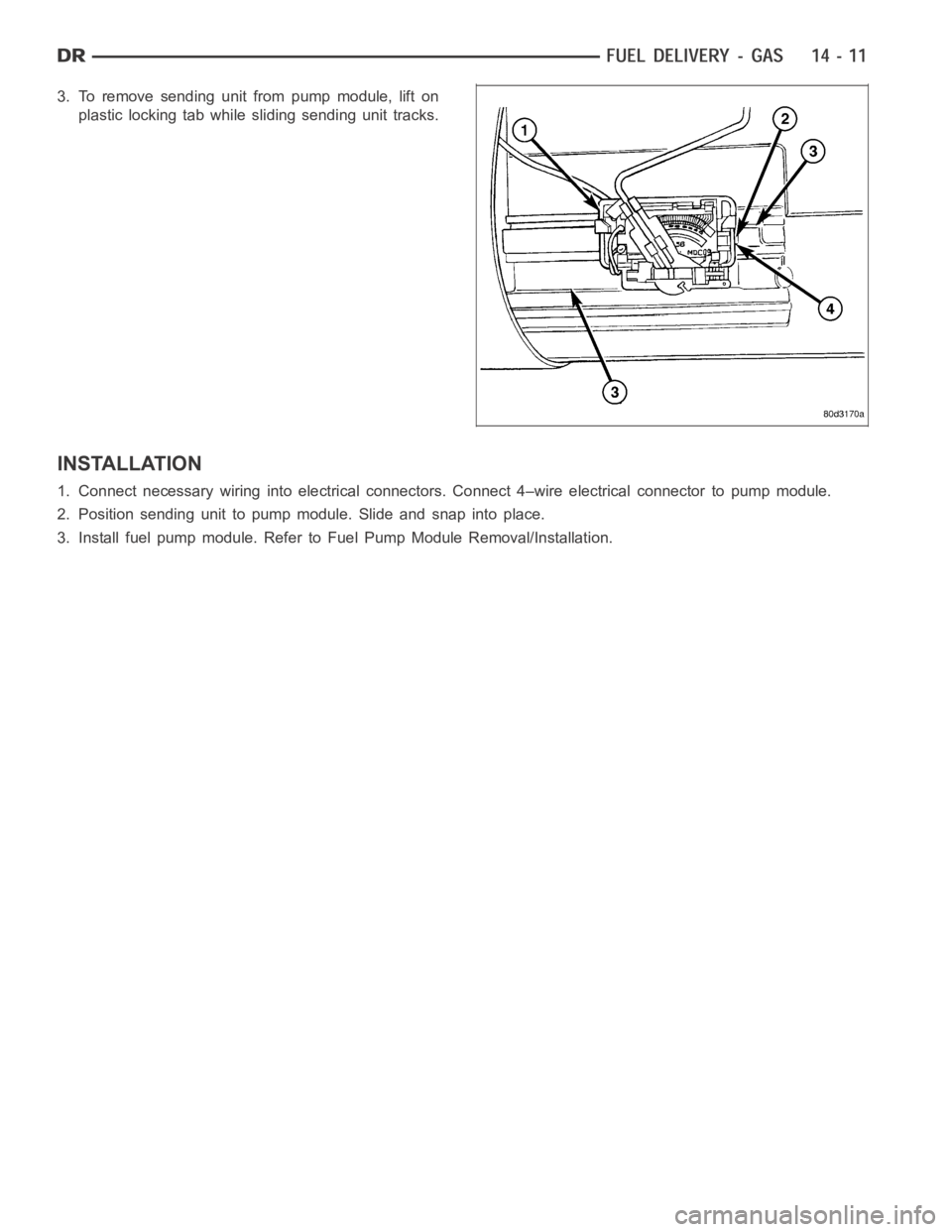
3. To remove sending unit from pump module, lift on
plastic locking tab whilesliding sending unit tracks.
INSTALLATION
1. Connect necessary wiring into electrical connectors. Connect 4–wire electrical connector to pump module.
2. Position sending unit to pump module. Slide and snap into place.
3. Install fuel pump module. Refer to Fuel Pump Module Removal/Installation.