Page 1468 of 5267
*CHECKING A/C SYSTEM OPERATION WITH NO DTCS
For a complete wiring diagramRefer to Section 8W.
Page 1472 of 5267
*CHECKING CHARGING SYSTEM OPERATION WITH NO DTCS
For a complete wiring diagramRefer to Section 8W.
Page 1476 of 5267
*CHECKING RADIATOR FAN OPERATION
For a complete wiring diagramRefer to Section 8W.
Page 1478 of 5267
*CHECKING THE PCM POWER AND GROUNDS
For a complete wiring diagramRefer to Section 8W.
Page 1481 of 5267

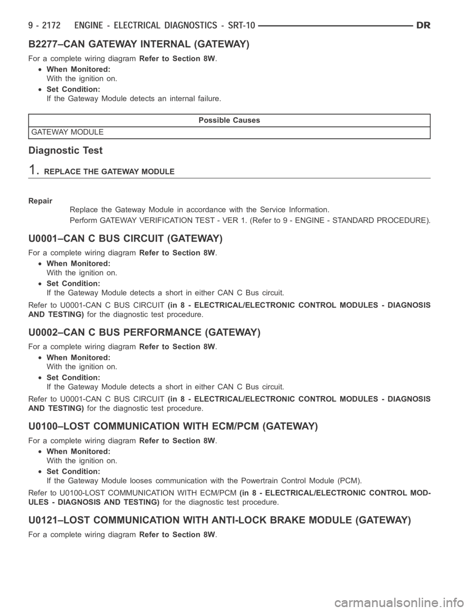
B2277–CAN GATEWAY INTERNAL (GATEWAY)
For a complete wiring diagramRefer to Section 8W.
When Monitored:
With the ignition on.
Set Condition:
If the Gateway Module detects an internal failure.
Possible Causes
GATEWAY MODULE
Diagnostic Test
1.REPLACE THE GATEWAY MODULE
Repair
Replace the Gateway Module in accordance with the Service Information.
Perform GATEWAY VERIFICATION TEST - VER 1. (Refer to 9 - ENGINE - STANDARD PROCEDURE).
U0001–CAN C BUS CIRCUIT (GATEWAY)
For a complete wiring diagramRefer to Section 8W.
When Monitored:
With the ignition on.
Set Condition:
If the Gateway Module detects a short in either CAN C Bus circuit.
Refer to U0001-CAN C BUS CIRCUIT(in 8 - ELECTRICAL/ELECTRONIC CONTROL MODULES - DIAGNOSIS
AND TESTING)for the diagnostic test procedure.
U0002–CAN C BUS PERFORMANCE (GATEWAY)
For a complete wiring diagramRefer to Section 8W.
When Monitored:
With the ignition on.
Set Condition:
If the Gateway Module detects a short in either CAN C Bus circuit.
Refer to U0001-CAN C BUS CIRCUIT(in 8 - ELECTRICAL/ELECTRONIC CONTROL MODULES - DIAGNOSIS
AND TESTING)for the diagnostic test procedure.
U0100–LOST COMMUNICATION WITH ECM/PCM (GATEWAY)
For a complete wiring diagramRefer to Section 8W.
When Monitored:
With the ignition on.
Set Condition:
If the Gateway Module looses communication with the Powertrain Control Module (PCM).
Refer to U0100-LOST COMMUNICATION WITH ECM/PCM(in 8 - ELECTRICAL/ELECTRONIC CONTROL MOD-
ULES - DIAGNOSIS AND TESTING)for the diagnostic test procedure.
U0121–LOST COMMUNICATION WITH ANTI-LOCK BRAKE MODULE (GATEWAY)
For a complete wiring diagramRefer to Section 8W.
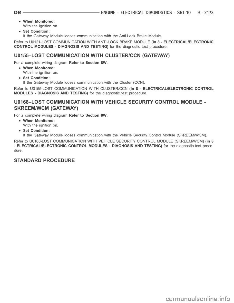
Page 1482 of 5267

When Monitored:
With the ignition on.
Set Condition:
If the Gateway Module looses communication with the Anti-Lock Brake Module.
Refer to U0121-LOST COMMUNICATION WITH ANTI-LOCK BRAKE MODULE(in 8 - ELECTRICAL/ELECTRONIC
CONTROL MODULES - DIAGNOSIS AND TESTING)for the diagnostic test procedure.
U0155–LOST COMMUNICATION WITH CLUSTER/CCN (GATEWAY)
For a complete wiring diagramRefer to Section 8W.
When Monitored:
With the ignition on.
Set Condition:
If the Gateway Module looses communication with the Cluster (CCN).
Refer to U0155-LOST COMMUNICATION WITH CLUSTER/CCN(in 8 - ELECTRICAL/ELECTRONIC CONTROL
MODULES - DIAGNOSIS AND TESTING)for the diagnostic test procedure.
U0168–LOST COMMUNICATION WITHVEHICLE SECURITY CONTROL MODULE -
SKREEM/WCM (GATEWAY)
For a complete wiring diagramRefer to Section 8W.
When Monitored:
With the ignition on.
Set Condition:
If the Gateway Module looses communication with the Vehicle Security Control Module (SKREEM/WCM).
Refer to U0168-LOST COMMUNICATION WITH VEHICLE SECURITY CONTROL MODULE (SKREEM/WCM)(in 8
- ELECTRICAL/ELECTRONIC CONTROL MODULES - DIAGNOSIS AND TESTING)for the diagnostic test proce-
dure.
STANDARD PROCEDURE
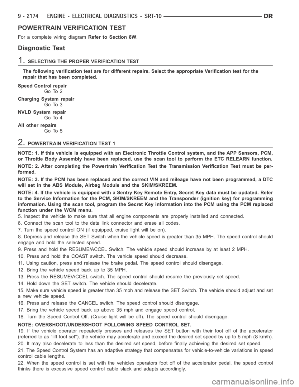
Page 1483 of 5267

POWERTRAIN VERIFICATION TEST
For a complete wiring diagramRefer to Section 8W.
Diagnostic Test
1.SELECTING THE PROPER VERIFICATION TEST
The following verification test are for different repairs. Select the appropriate Verification test for the
repair that has been completed.
Speed Control repair
Go To 2
Charging System repair
Go To 3
NVLD System repair
Go To 4
All other repairs
Go To 5
2.POWERTRAIN VERIFICATION TEST 1
NOTE: 1. If this vehicle is equipped with an Electronic Throttle Control system, and the APP Sensors, PCM,
or Throttle Body Assembly have been replaced, use the scan tool to perform the ETC RELEARN function.
NOTE: 2. After completing the Powertrain Verification Test the Transmission Verification Test must be per-
formed.
NOTE: 3. If the PCM has been replaced and the correct VIN and mileage have notbeen programmed, a DTC
will set in the ABS Module, Airbag Module and the SKIM/SKREEM.
NOTE: 4. If the vehicle is equipped with a Sentry Key Remote Entry, Secret Key data must be updated. Refer
to the Service Information for the PCM, SKIM/SKREEM and the Transponder (ignition key) for programming
information. Using the scan tool, program the Secret Key information intothe PCM using the PCM replaced
function under the WCM menu.
5. Inspect the vehicle to make sure that all engine components are properlyinstalled and connected.
6. Connect the scan tool to the data link connector and erase all codes.
7. Turn the speed control ON (if equipped, cruise light will be on).
8. Depress and release the SET Switch when the vehicle speed is greater than35 MPH. The speed control should
engage and hold the selected speed.
9. Press and hold the RESUME/ACCEL Switch. The vehicle speed should increase by at least 2 MPH.
10. Press and hold the COAST switch. The vehicle speed should decrease.
11. Using caution, press and release the brake pedal. The speed control should disengage.
12. Bring the vehicle speed back up to 35 MPH.
13. Press the RESUME/ACCEL switch. The speed control should resume the previously set speed.
14. Hold down the SET switch. The vehicle should decelerate.
15. Make sure vehicle speed is greater than 35 mph and release the SET Switch. The vehicle should adjust and set
a new vehicle speed.
16. Press and release the CANCEL switch. The speed control should disengage.
17. Bring the vehicle speed back up above 35 mph and engage speed control.
18. Turn the Speed Control Off. (Cruise light will be off). The speed control should disengage.
NOTE: OVERSHOOT/UNDERSHOOT FOLLOWING SPEED CONTROL SET.
19. If the vehicle operator repeatedly presses and releases the SET buttonwith their foot off of the accelerator
(referred to as
lift foot set), the vehicle may accelerate and exceed the desired set speed by up to 5 mph (8km/h).
20. It may also decelerate to less than the desired set speed, before finally achieving the desired set speed.
21. The Speed Control System has an adaptive strategy that compensates forvehicle-to-vehicle variations in speed
control cable lengths.
22. When the speed control is set with the vehicles operators foot off of theaccelerator pedal, the speed control
thinks there is excessive speed control cable slack and adapts accordingly.
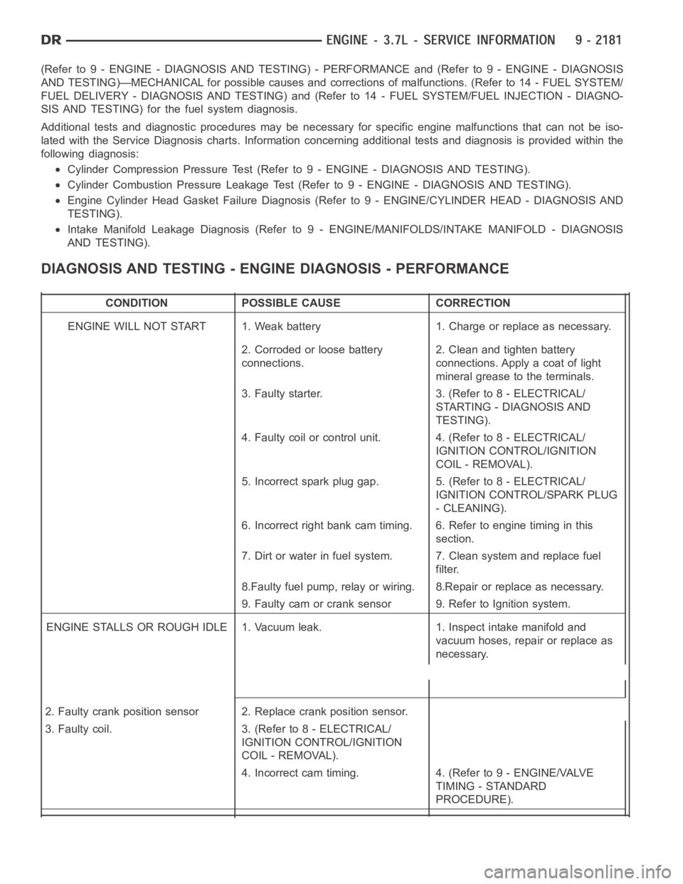
Page 1490 of 5267

(Refer to 9 - ENGINE - DIAGNOSIS AND TESTING) - PERFORMANCE and (Refer to 9 - ENGINE - DIAGNOSIS
AND TESTING)—MECHANICAL for possible causes and corrections of malfunctions. (Refer to 14 - FUEL SYSTEM/
FUEL DELIVERY - DIAGNOSIS AND TESTING) and (Refer to 14 - FUEL SYSTEM/FUEL INJECTION - DIAGNO-
SIS AND TESTING) for the fuel system diagnosis.
Additional tests and diagnostic procedures may be necessary for specificengine malfunctions that can not be iso-
lated with the Service Diagnosis charts. Information concerning additional tests and diagnosis is provided within the
following diagnosis:
Cylinder Compression Pressure Test (Refer to 9 - ENGINE - DIAGNOSIS AND TESTING).
Cylinder Combustion Pressure LeakageTest (Refer to 9 - ENGINE - DIAGNOSISAND TESTING).
Engine Cylinder Head Gasket Failure Diagnosis (Refer to 9 - ENGINE/CYLINDER HEAD - DIAGNOSIS AND
TESTING).
Intake Manifold Leakage Diagnosis (Refer to 9 - ENGINE/MANIFOLDS/INTAKEMANIFOLD - DIAGNOSIS
AND TESTING).
DIAGNOSIS AND TESTING - ENGINE DIAGNOSIS - PERFORMANCE
CONDITION POSSIBLE CAUSE CORRECTION
ENGINE WILL NOT START 1. Weak battery 1. Charge or replace as necessary.
2. Corroded or loose battery
connections.2. Clean and tighten battery
connections. Apply a coat of light
mineral grease to the terminals.
3. Faulty starter. 3. (Refer to 8 - ELECTRICAL/
STARTING - DIAGNOSIS AND
TESTING).
4. Faulty coil or control unit. 4. (Refer to 8 - ELECTRICAL/
IGNITION CONTROL/IGNITION
COIL - REMOVAL).
5. Incorrect spark plug gap. 5. (Refer to 8 - ELECTRICAL/
IGNITION CONTROL/SPARK PLUG
- CLEANING).
6. Incorrect right bank cam timing. 6. Refer to engine timing in this
section.
7. Dirt or water in fuel system. 7. Clean system and replace fuel
filter.
8.Faulty fuel pump, relay or wiring. 8.Repair or replace as necessary.
9. Faulty cam or crank sensor 9. Refer to Ignition system.
ENGINE STALLS OR ROUGH IDLE 1. Vacuum leak. 1. Inspect intake manifold and
vacuum hoses, repair or replace as
necessary.
2. Faulty crank position sensor 2. Replace crank position sensor.
3. Faulty coil. 3. (Refer to 8 - ELECTRICAL/
IGNITION CONTROL/IGNITION
COIL - REMOVAL).
4. Incorrect cam timing. 4. (Refer to 9 - ENGINE/VALVE
TIMING - STANDARD
PROCEDURE).