Page 1498 of 5267
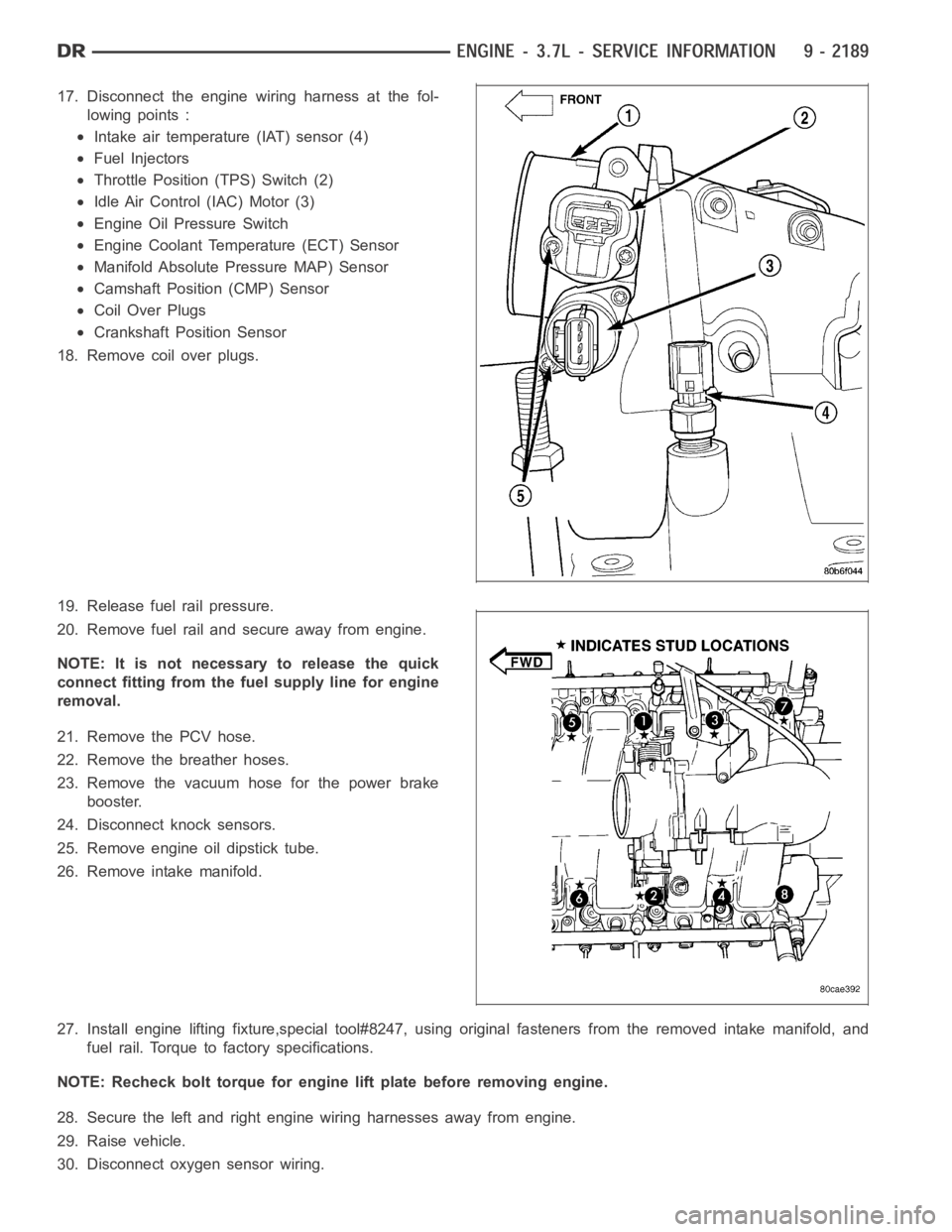
17. Disconnect the engine wiring harness at the fol-
lowing points :
Intake air temperature (IAT) sensor (4)
Fuel Injectors
Throttle Position (TPS) Switch (2)
Idle Air Control (IAC) Motor (3)
Engine Oil Pressure Switch
Engine Coolant Temperature (ECT) Sensor
Manifold Absolute Pressure MAP) Sensor
Camshaft Position (CMP) Sensor
Coil Over Plugs
Crankshaft Position Sensor
18. Remove coil over plugs.
19. Release fuel rail pressure.
20. Remove fuel rail and secure away from engine.
NOTE: It is not necessary to release the quick
connect fitting from the fuel supply line for engine
removal.
21. Remove the PCV hose.
22. Remove the breather hoses.
23. Remove the vacuum hose for the power brake
booster.
24. Disconnect knock sensors.
25. Remove engine oil dipstick tube.
26. Remove intake manifold.
27. Install engine lifting fixture,special tool#8247, using original fasteners from the removed intake manifold, and
fuel rail. Torque to factory specifications.
NOTE: Recheck bolt torque for engine lift plate before removing engine.
28. Secure the left and right engine wiring harnesses away from engine.
29. Raise vehicle.
30. Disconnect oxygen sensor wiring.
Page 1503 of 5267
25. Connect the engine wiring harness at the follow-
ing points :
Intake air temperature (IAT) sensor (4)
Fuel Injectors
Throttle Position (TPS) Switch (2)
Idle Air Control (IAC) Motor (3)
Engine Oil Pressure Switch
Engine Coolant Temperature (ECT) Sensor
Manifold Absolute Pressure MAP) Sensor
Camshaft Position (CMP) Sensor
Coil Over Plugs
Crankshaft Position Sensor
26. Reinstall the radiator/cooling module assembly.
27. Connect lower radiator hose.
28. Connect upper radiator hose.
29. Connect throttle and speed control cables.
30. Install the heater hose assembly.
31. Install coolant recovery bottle.
32. Install the power steering pump.
33. Install the generator (3).
Page 1625 of 5267
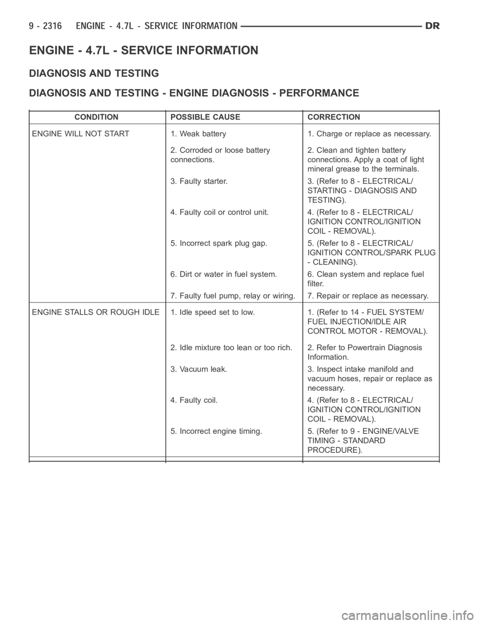
ENGINE - 4.7L - SERVICE INFORMATION
DIAGNOSIS AND TESTING
DIAGNOSIS AND TESTING - ENGINE DIAGNOSIS - PERFORMANCE
CONDITION POSSIBLE CAUSE CORRECTION
ENGINE WILL NOT START 1. Weak battery 1. Charge or replace as necessary.
2. Corroded or loose battery
connections.2. Clean and tighten battery
connections. Apply a coat of light
mineral grease to the terminals.
3. Faulty starter. 3. (Refer to 8 - ELECTRICAL/
STARTING - DIAGNOSIS AND
TESTING).
4. Faulty coil or control unit. 4. (Refer to 8 - ELECTRICAL/
IGNITION CONTROL/IGNITION
COIL - REMOVAL).
5. Incorrect spark plug gap. 5. (Refer to 8 - ELECTRICAL/
IGNITION CONTROL/SPARK PLUG
- CLEANING).
6. Dirt or water in fuel system. 6. Clean system and replace fuel
filter.
7. Faulty fuel pump, relay or wiring. 7. Repair or replace as necessary.
ENGINE STALLS OR ROUGH IDLE 1. Idle speed set to low. 1. (Refer to 14 - FUEL SYSTEM/
FUEL INJECTION/IDLE AIR
CONTROL MOTOR - REMOVAL).
2. Idle mixture too lean or too rich. 2. Refer to Powertrain Diagnosis
Information.
3. Vacuum leak. 3. Inspect intake manifold and
vacuum hoses, repair or replace as
necessary.
4. Faulty coil. 4. (Refer to 8 - ELECTRICAL/
IGNITION CONTROL/IGNITION
COIL - REMOVAL).
5. Incorrect engine timing. 5. (Refer to 9 - ENGINE/VALVE
TIMING - STANDARD
PROCEDURE).
Page 1637 of 5267
6. Position generator wiring behind the oil dipstick
tube, then install the oil dipstick tube upper mount-
ing bolt.
7. Connect both left (2) and right (3) side body ground
straps.
8. Install power steering pump.
9. Connect fuel supply line quick connect fitting (Refer
to 14 - FUEL SYSTEM/FUEL DELIVERY/QUICK
CONNECT FITTING - STANDARD PROCEDURE).
10. Connect the vacuum lines at the throttle body and
intake manifold.
11. Connect engine harness at the following points :
Intake Air Temperature (IAT) Sensor (4)
Idle Air Control (IAC) Motor (3)
Fuel Injectors
Throttle Position (TPS) Switch (2)
Engine Oil Pressure Switch
Engine Coolant Temperature (ECT) Sensor
Manifold Absolute Pressure (MAP) Sensor
Camshaft Position (CMP) Sensor
Coil Over Plugs
Page 1758 of 5267
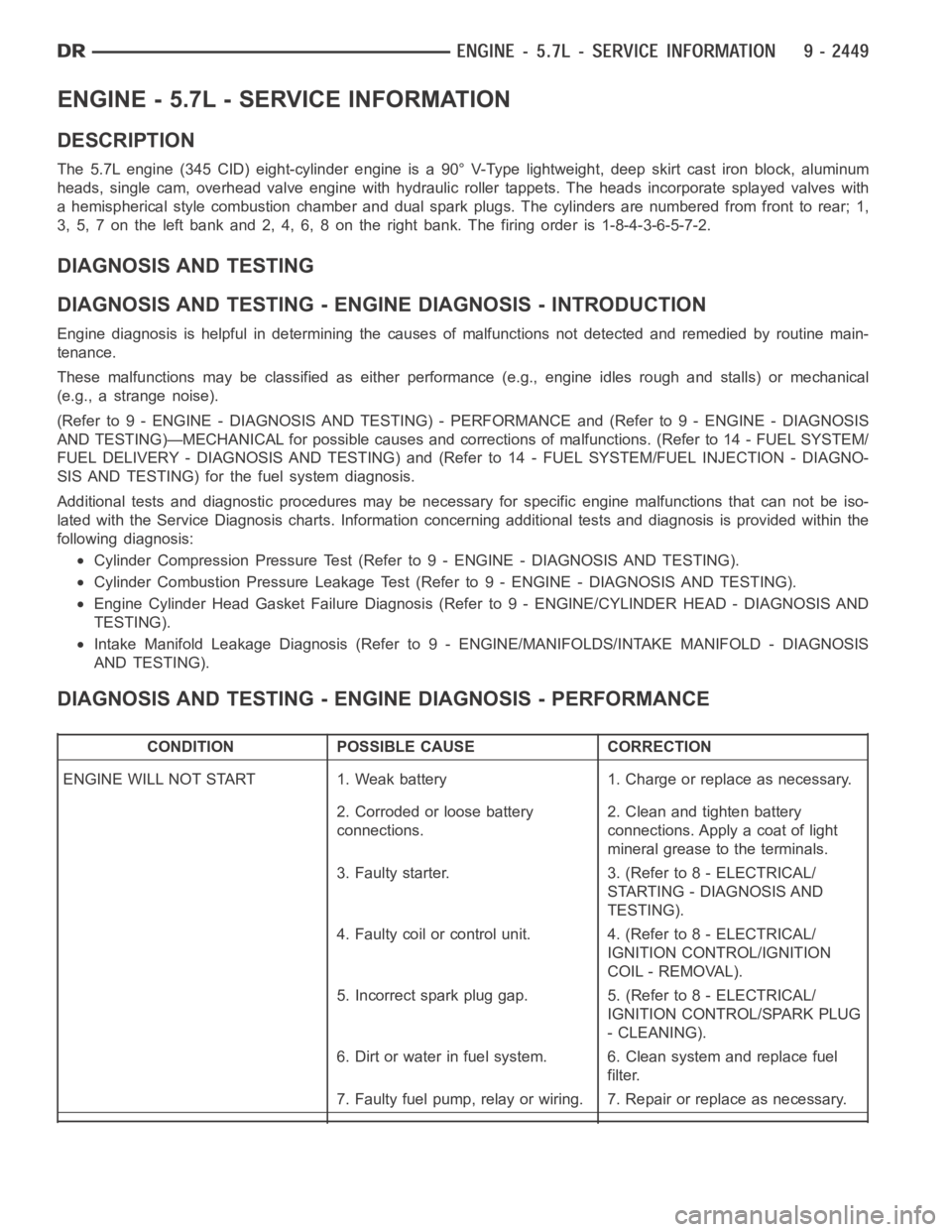
ENGINE - 5.7L - SERVICE INFORMATION
DESCRIPTION
The 5.7L engine (345 CID) eight-cylinder engine is a 90° V-Type lightweight, deep skirt cast iron block, aluminum
heads, single cam, overhead valve engine with hydraulic roller tappets. The heads incorporate splayed valves with
a hemispherical style combustion chamber and dual spark plugs. The cylinders are numbered from front to rear; 1,
3, 5, 7 on the left bank and 2, 4, 6, 8 on the right bank. The firing order is 1-8-4-3-6-5-7-2.
DIAGNOSIS AND TESTING
DIAGNOSIS AND TESTING - ENGINE DIAGNOSIS - INTRODUCTION
Engine diagnosis is helpful in determining the causes of malfunctions notdetected and remedied by routine main-
tenance.
These malfunctions may be classified as either performance (e.g., engineidles rough and stalls) or mechanical
(e.g., a strange noise).
(Refer to 9 - ENGINE - DIAGNOSIS AND TESTING) - PERFORMANCE and (Refer to 9 - ENGINE - DIAGNOSIS
AND TESTING)—MECHANICAL for possible causes and corrections of malfunctions. (Refer to 14 - FUEL SYSTEM/
FUEL DELIVERY - DIAGNOSIS AND TESTING) and (Refer to 14 - FUEL SYSTEM/FUEL INJECTION - DIAGNO-
SIS AND TESTING) for the fuel system diagnosis.
Additional tests and diagnostic procedures may be necessary for specificengine malfunctions that can not be iso-
lated with the Service Diagnosis charts. Information concerning additional tests and diagnosis is provided within the
following diagnosis:
Cylinder Compression Pressure Test (Refer to 9 - ENGINE - DIAGNOSIS AND TESTING).
Cylinder Combustion Pressure LeakageTest (Refer to 9 - ENGINE - DIAGNOSISAND TESTING).
Engine Cylinder Head Gasket Failure Diagnosis (Refer to 9 - ENGINE/CYLINDER HEAD - DIAGNOSIS AND
TESTING).
Intake Manifold Leakage Diagnosis (Refer to 9 - ENGINE/MANIFOLDS/INTAKEMANIFOLD - DIAGNOSIS
AND TESTING).
DIAGNOSIS AND TESTING - ENGINE DIAGNOSIS - PERFORMANCE
CONDITION POSSIBLE CAUSE CORRECTION
ENGINE WILL NOT START 1. Weak battery 1. Charge or replace as necessary.
2. Corroded or loose battery
connections.2. Clean and tighten battery
connections. Apply a coat of light
mineral grease to the terminals.
3. Faulty starter. 3. (Refer to 8 - ELECTRICAL/
STARTING - DIAGNOSIS AND
TESTING).
4. Faulty coil or control unit. 4. (Refer to 8 - ELECTRICAL/
IGNITION CONTROL/IGNITION
COIL - REMOVAL).
5. Incorrect spark plug gap. 5. (Refer to 8 - ELECTRICAL/
IGNITION CONTROL/SPARK PLUG
- CLEANING).
6. Dirt or water in fuel system. 6. Clean system and replace fuel
filter.
7. Faulty fuel pump, relay or wiring. 7. Repair or replace as necessary.
Page 1868 of 5267
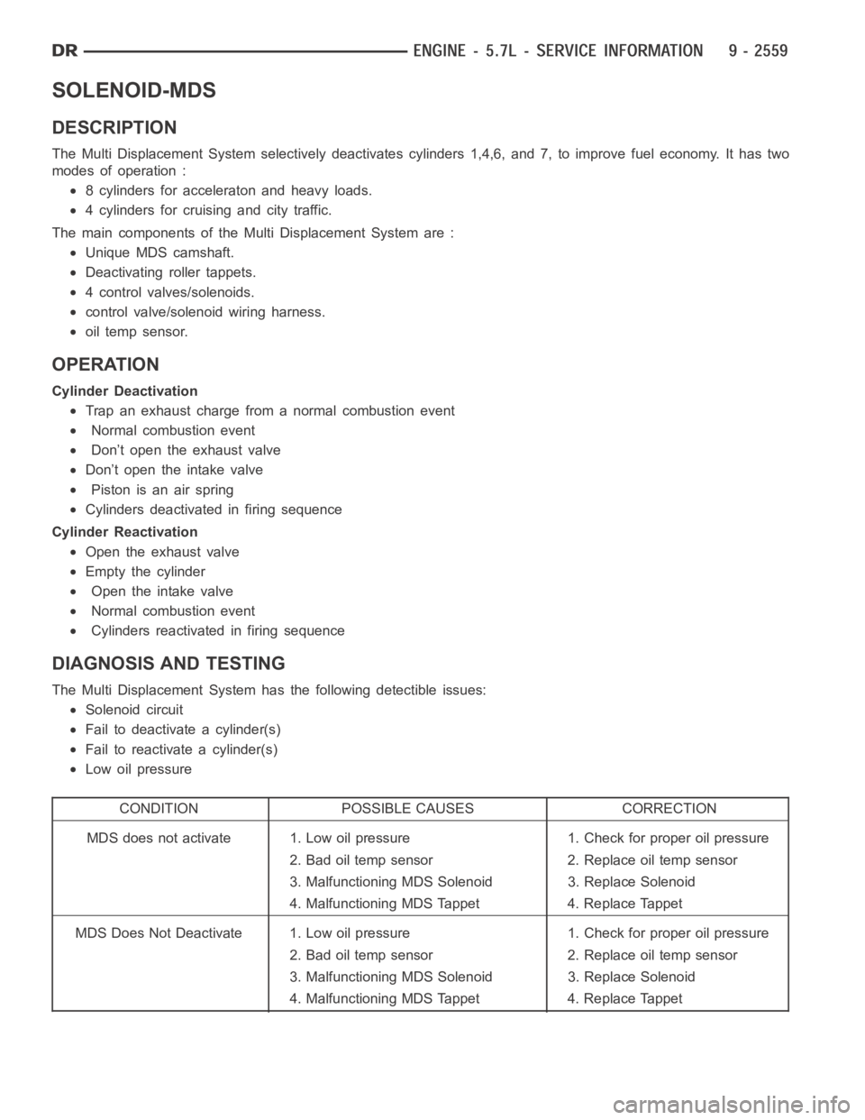
SOLENOID-MDS
DESCRIPTION
The Multi Displacement System selectively deactivates cylinders 1,4,6,and 7, to improve fuel economy. It has two
modes of operation :
8 cylinders for acceleraton and heavy loads.
4 cylinders for cruising and city traffic.
The main components of the Multi Displacement System are :
Unique MDS camshaft.
Deactivating roller tappets.
4 control valves/solenoids.
control valve/solenoid wiring harness.
oil temp sensor.
OPERATION
Cylinder Deactivation
Trap an exhaust charge from a normal combustion event
Normal combustion event
Don’t open the exhaust valve
Don’t open the intake valve
Piston is an air spring
Cylinders deactivated in firing sequence
Cylinder Reactivation
Open the exhaust valve
Empty the cylinder
Open the intake valve
Normal combustion event
Cylinders reactivated in firing sequence
DIAGNOSIS AND TESTING
The Multi Displacement System has the following detectible issues:
Solenoid circuit
Fail to deactivate a cylinder(s)
Fail to reactivate a cylinder(s)
Low oil pressure
CONDITION POSSIBLE CAUSES CORRECTION
MDS does not activate 1. Low oil pressure 1. Check for proper oil pressure
2. Bad oil temp sensor 2. Replace oil temp sensor
3. Malfunctioning MDS Solenoid 3. Replace Solenoid
4. Malfunctioning MDS Tappet 4. Replace Tappet
MDS Does Not Deactivate 1. Low oil pressure 1. Check for proper oil pressure
2. Bad oil temp sensor 2. Replace oil temp sensor
3. Malfunctioning MDS Solenoid 3. Replace Solenoid
4. Malfunctioning MDS Tappet 4. Replace Tappet
Page 1869 of 5267
REMOVAL
1. Disconnect the negative battery cable.
2. Remove the intake manifold. (Refer to 9 - ENGINE/MANIFOLDS/INTAKE MANIFOLD - REMOVAL).
3. Remove wiring harness connectors from the MDS solenoids.
4. Remove hold down bolt from MDS solenoid.
5. Remove MDS solenoid.
INSTALLATION
1. Verify that MDS bores are free of debris, before solenoid installation.
2. Install MDS solenoid fully into block.
3. Install hold down bolt and torque to 11 Nꞏm (97 in. lbs.).
4. Reconnect the MDS wiring harness to the solenoids.
5. Install the intake manifold. (Refer to 9 - ENGINE/MANIFOLDS/INTAKE MANIFOLD - INSTALLATION).
Page 1919 of 5267
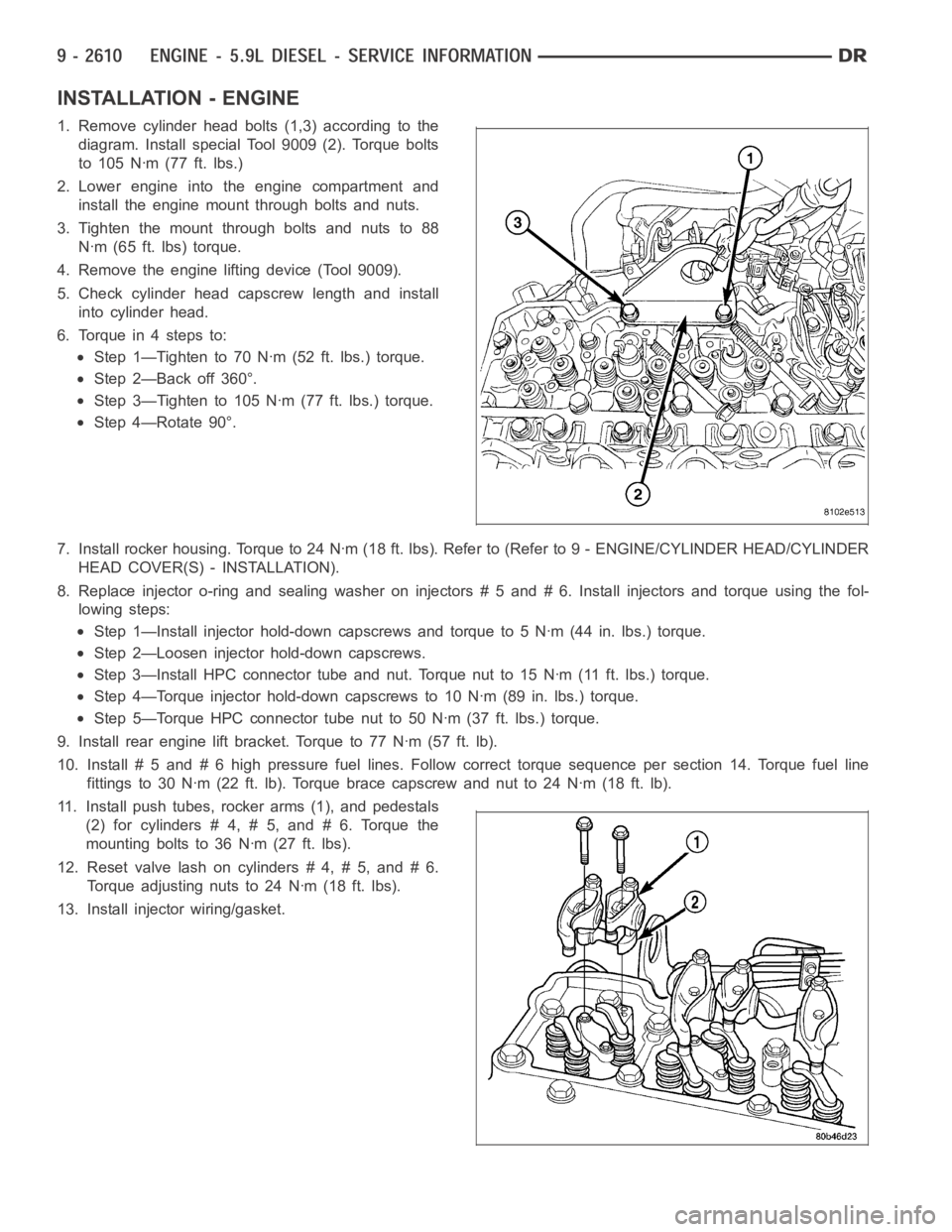
INSTALLATION - ENGINE
1. Remove cylinder head bolts (1,3) according to the
diagram. Install special Tool 9009 (2). Torque bolts
to 105 Nꞏm (77 ft. lbs.)
2. Lower engine into the engine compartment and
install the engine mount through bolts and nuts.
3. Tighten the mount through bolts and nuts to 88
Nꞏm (65 ft. lbs) torque.
4. Remove the engine lifting device (Tool 9009).
5. Check cylinder head capscrew length and install
into cylinder head.
6. Torque in 4 steps to:
Step 1—Tighten to 70 Nꞏm (52 ft. lbs.) torque.
Step 2—Back off 360°.
Step 3—Tighten to 105 Nꞏm (77 ft. lbs.) torque.
Step 4—Rotate 90°.
7. Install rocker housing. Torque to 24 Nꞏm (18 ft. lbs). Refer to (Refer to 9- ENGINE/CYLINDER HEAD/CYLINDER
HEAD COVER(S) - INSTALLATION).
8. Replace injector o-ring and sealing washer on injectors # 5 and # 6. Install injectors and torque using the fol-
lowing steps:
Step 1—Install injector hold-down capscrews and torque to 5 Nꞏm (44 in. lbs.) torque.
Step 2—Loosen injector hold-down capscrews.
Step 3—Install HPC connector tube and nut. Torque nut to 15 Nꞏm (11 ft. lbs.)torque.
Step 4—Torque injector hold-down capscrews to 10 Nꞏm (89 in. lbs.) torque.
Step 5—Torque HPC connector tube nut to 50 Nꞏm (37 ft. lbs.) torque.
9. Install rear engine lift bracket. Torque to 77 Nꞏm (57 ft. lb).
10. Install # 5 and # 6 high pressure fuel lines. Follow correct torque sequence per section 14. Torque fuel line
fittings to 30 Nꞏm (22 ft. lb). Torque brace capscrew and nut to 24 Nꞏm (18 ft.lb).
11. Install push tubes, rocker arms (1), and pedestals
(2) for cylinders # 4, # 5, and # 6. Torque the
mounting bolts to 36 Nꞏm (27 ft. lbs).
12. Reset valve lash on cylinders # 4, # 5, and # 6.
Torque adjusting nuts to 24 Nꞏm (18 ft. lbs).
13. Install injector wiring/gasket.