2006 DODGE RAM SRT-10 battery
[x] Cancel search: batteryPage 1679 of 5267
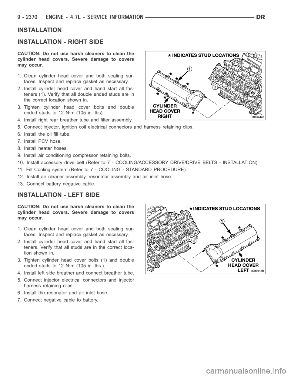
INSTALLATION
INSTALLATION - RIGHT SIDE
CAUTION: Do not use harsh cleaners to clean the
cylinder head covers. Severe damage to covers
may occur.
1. Clean cylinder head cover and both sealing sur-
faces. Inspect and replace gasket as necessary.
2. Install cylinder head cover and hand start all fas-
teners (1). Verify that all double ended studs are in
the correct location shown in.
3. Tighten cylinder head cover bolts and double
ended studs to 12 Nꞏm (105 in. lbs).
4. Install right rear breather tube and filter assembly.
5. Connect injector, ignition coil electrical connectors and harness retaining clips.
6. Install the oil fill tube.
7. Install PCV hose.
8. Install heater hoses.
9. Install air conditioning compressor retaining bolts.
10. Install accessory drive belt (Refer to 7 - COOLING/ACCESSORY DRIVE/DRIVE BELTS - INSTALLATION).
11. Fill Cooling system (Refer to 7 - COOLING - STANDARD PROCEDURE).
12. Install air cleaner assembly, resonator assembly and air inlet hose.
13. Connect battery negative cable.
INSTALLATION - LEFT SIDE
CAUTION: Do not use harsh cleaners to clean the
cylinder head covers. Severe damage to covers
may occur.
1. Clean cylinder head cover and both sealing sur-
faces. Inspect and replace gasket as necessary.
2. Install cylinder head cover and hand start all fas-
teners. Verify that all studs are in the correct loca-
tion shown in.
3. Tighten cylinder head cover bolts (1) and double
ended studs to 12 Nꞏm (105 in. lbs.).
4. Install left side breather and connect breather tube.
5. Connect injector electrical connectors and injector
harness retaining clips.
6. Install the resonator and air inlet hose.
7. Connect negative cable to battery.
Page 1683 of 5267
ROCKER ARM - VALVE
DESCRIPTION
The rocker arms are steel stampings with an integral roller bearing. The rocker arms incorporate an 0.5 mm (0.019
inch) oil hole in the ball socket forroller and camshaft lubrication.
DIAGNOSIS AND TESTING - HYDRAULIC LASH ADJUSTER
A tappet-like noise may be produced from several items. Check the followingitems.
1. Engine oil level too high or too low. This may cause aerated oil to enter the adjusters and cause them to be
spongy.
2. Insufficient running time after rebuilding cylinder head. Low speed runningupto1hourmayberequired.
3. Turn engine off and let set for a few minutes before restarting. Repeat this several times after engine has
reached normal operating temperature.
4. Low oil pressure.
5. The oil restrictor in cylinder head gasket or the oil passage to the cylinder head is plugged with debris.
6. Airingestedintooilduetobrokenorcrackedoilpumppickup.
7. Worn valve guides.
8. Rocker arm ears contacting valve spring retainer.
9. Rocker arm loose, adjuster stuck or at maximum extension and still leaves lash in the system.
10. Oil leak or excessive cam bore wear in cylinder head.
11. Faulty lash adjuster.
a. Check lash adjusters for sponginess while installed in cylinder head and cam on camshaft at base circle.
Depress part of rocker arm over adjuster. Normal adjusters should feel very firm. Spongy adjusters can be bot-
tomed out easily.
b. Remove suspected lash adjusters, and replace.
c. Before installation, make sure adjusters are at least partially full ofoil. This can be verified by little or no
plunger travel when lash adjuster is depressed.
REMOVAL
NOTE: Disconnect the battery negative cable to
prevent accidental starter engagement.
1. Remove the cylinder head cover (Refer to 9 -
ENGINE/CYLINDER HEAD/CYLINDER HEAD
COVER(S) - REMOVAL).
2. For rocker arm removal on cylinders 3 and 5
Rotate the crankshaft until cylinder #1 is at TDC
exhaust stroke.
3. For rocker arm removal on cylinders 2 and 8
Rotate the crankshaft until cylinder #1 is at TDC
compression stroke.
4. For rocker arm removal on cylinders 4 and 6
Rotate the crankshaft until cylinder #3 is at TDC
compression stroke.
5. For rocker arm removal on cylinders 1 and 7
Rotate the crankshaft until cylinder #2 is at TDC
compression stroke.
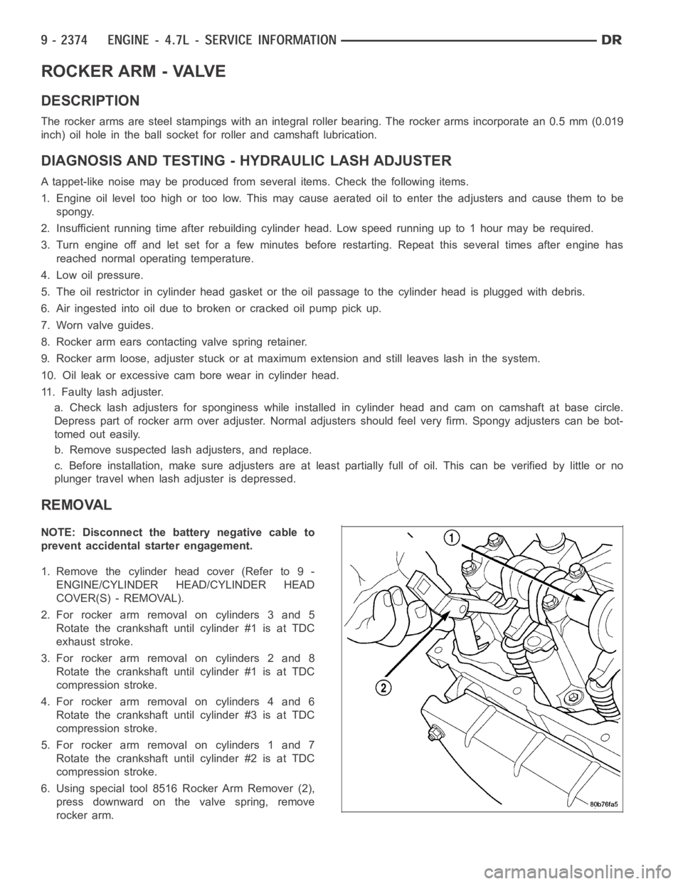
6. Using special tool 8516 Rocker Arm Remover (2),
press downward on the valve spring, remove
rocker arm.
Page 1700 of 5267
SEAL - CRANKSHAFT OIL - FRONT
REMOVAL
1. Disconnect negative cable from battery.
2. Remove accessory drive belt (Refer to 7 - COOL-
ING/ACCESSORY DRIVE/DRIVE BELTS -
REMOVAL).
3. Remove A/C compressor mouning fasteners and
set aside.
4. Drain cooling system (Refer to 7 - COOLING -
STANDARD PROCEDURE).
5. Remove upper radiator hose.
6. Disconnect electrical connector for fan mounted
inside radiator shroud.
7. Remove radiator shroud attaching fasteners.
NOTE: Transmission cooler line snaps into shroud
lower right hand corner.
8. Remove radiator cooling fan and shroud (Refer to
7 - COOLING/ENGINE/RADIATOR FAN -
REMOVAL).
9. Remove crankshaft damper bolt.
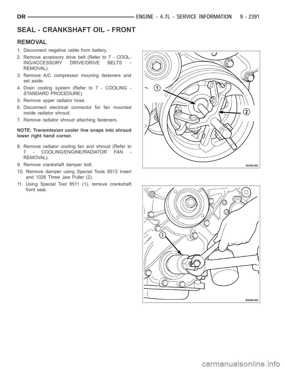
10. Remove damper using Special Tools 8513 Insert
and 1026 Three Jaw Puller (2).
11. Using Special Tool 8511 (1), remove crankshaft
front seal.
Page 1701 of 5267
INSTALLATION
CAUTION: To prevent severe damage to the Crank-
shaft, Damper or Special Tool 8512, thoroughly
clean the damper bore and the crankshaft nose
before installing Damper.
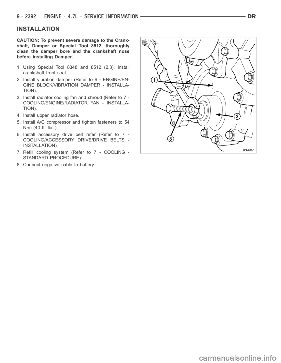
1. Using Special Tool 8348 and 8512 (2,3), install
crankshaft front seal.
2. Install vibration damper (Refer to 9 - ENGINE/EN-
GINE BLOCK/VIBRATION DAMPER - INSTALLA-
TION).
3. Installradiatorcoolingfanandshroud(Referto7-
COOLING/ENGINE/RADIATOR FAN - INSTALLA-
TION).
4. Install upper radiator hose.
5. Install A/C compressor and tighten fasteners to 54
Nꞏm (40 ft. lbs.).
6. Install accessory drive belt refer (Refer to 7 -
COOLING/ACCESSORY DRIVE/DRIVE BELTS -
INSTALLATION).
7. Refill cooling system (Refer to 7 - COOLING -
STANDARD PROCEDURE).
8. Connect negative cable to battery.
Page 1702 of 5267
SEAL - CRANKSHAFT OIL - REAR
DIAGNOSIS AND TESTING - REAR SEAL AREA LEAKS
Since it is sometimes difficult to determine the source of an oil leak in therear seal area of the engine, a more
involved inspection is necessary. The following steps should be followedto help pinpoint the source of the leak.
If the leakage occurs at the crankshaft rear oil seal area:
1. Disconnect the battery.
2. Raise the vehicle.
3. Remove torque converter or clutch housing cover and inspect rear of block for evidence of oil. Use a black light
to check for the oil leak:
a. Circular spray pattern generally indicates seal leakage or crankshaftdamage.
b. Where leakage tends to run straight down, possible causes are a porous block, oil galley pipe plugs, oil filter
runoff, and main bearing cap to cylinder block mating surfaces. See Engine, for proper repair procedures of
these items.
4. If no leaks are detected, pressurized the crankcase as outlined in the section, Inspection (Engine oil Leaks in
general)
CAUTION: Do not exceed 20.6 kPa (3 psi).
5. If the leak is not detected, very slowly turn the crankshaft and watch forleakage. If a leak is detected between
the crankshaft and seal while slowly turning the crankshaft, it is possible the crankshaft seal surface is damaged.
The seal area on the crankshaft could have minor nicks or scratches that canbe polished out with emery cloth.
CAUTION: Use extreme caution when crankshaft polishing is necessary to remove minor nicks or
scratches. The crankshaft seal flange is specially machined to complement the function of the rear oil seal.
6. For bubbles that remain steady with shaft rotation, no further inspection can be done until disassembled. (Refer
to 9 - ENGINE - DIAGNOSIS AND TESTING), under the Oil Leak row, for components inspections on possible
causes and corrections.
7. After the oil leak root cause and appropriate corrective action have been identified, (Refer to 9 - ENGINE/EN-
GINE BLOCK/CRANKSHAFT OIL SEAL - REAR - REMOVAL).
REMOVAL
NOTE: This procedure can be performed in vehi-
cle.
1. If being performed in vehicle, remove the transmis-
sion.
2. Remove the flexplate (Refer to 9 - ENGINE/EN-
GINE BLOCK/FLEX PLATE - REMOVAL).
NOTE: The crankshaft oil seal CAN NOT be reused
after removal.
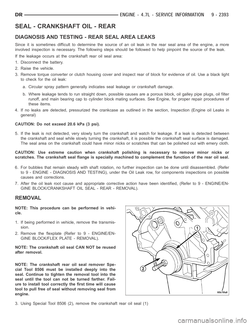
NOTE: The crankshaft rear oil seal remover Spe-
cial Tool 8506 must be installed deeply into the
seal. Continue to tighten the removal tool into the
seal until the tool can not be turned farther. Fail-
ure to install tool correctly the first time will cause
tool to pull free of seal without removing seal from
engine.
3. Using Special Tool 8506 (2), remove the crankshaft rear oil seal (1)
Page 1706 of 5267
REMOVAL
1. Disconnect negative cable from battery.
2. Remove the following components:
Oil pan and gasket/windage tray (Refer to 9 - ENGINE/LUBRICATION/OIL PAN -REMOVAL).
Cylinder head covers (Refer to 9 - ENGINE/CYLINDER HEAD/CYLINDER HEAD COVER(S) - REMOVAL) and
(Refer to 9 - ENGINE/CYLINDER HEAD/CYLINDER HEAD COVER(S) - REMOVAL).
Timing chain cover (Refer to 9 - ENGINE/VALVE TIMING/TIMING BELT / CHAIN COVER(S) - REMOVAL).
Cylinder head(s) (Refer to 9 - ENGINE/CYLINDER HEAD - REMOVAL) and (Refer to 9 - ENGINE/CYLINDER
HEAD - REMOVAL).
3. If necessary, remove top ridge of cylinder bores with a reliable ridge reamer before removing pistons from cyl-
inder block.Be sure to keep tops of pistons covered during this operation.Pistons and connecting rods
must be removed from top of cylinder block. When removing piston and connecting rod assemblies from the
engine, rotate crankshaft so the each connecting rod is centered in cylinder bore.
CAUTION: DO NOT use a number stamp or a punch to mark connecting rods or caps,as damage to con-
necting rods could occur
NOTE: Connecting rods and bearing caps are not interchangeable and shouldbe marked before removing
to ensure correct reassembly.
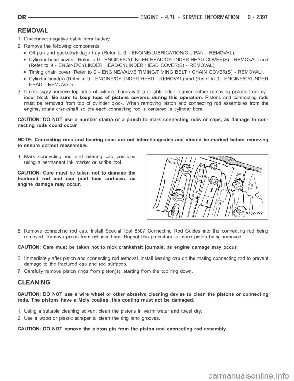
4. Mark connecting rod and bearing cap positions
using a permanent ink marker or scribe tool.
CAUTION: Care must be taken not to damage the
fractured rod and cap joint face surfaces, as
engine damage may occur.
5. Remove connecting rod cap. Install Special Tool 8507 Connecting Rod Guides into the connecting rod being
removed. Remove piston from cylinder bore. Repeat this procedure for eachpiston being removed.
CAUTION: Care must be taken not to nick crankshaft journals, as engine damage may occur
6. Immediately after piston and connecting rod removal, install bearing cap on the mating connecting rod to prevent
damage to the fractured cap and rod surfaces.
7. Carefully remove piston rings from piston(s), starting from the top ring down.
CLEANING
CAUTION: DO NOT use a wire wheel or other abrasive cleaning devise to clean the pistons or connecting
rods. The pistons have a Moly coating, this coating must not be damaged.
1. Using a suitable cleaning solvent clean the pistons in warm water and towel dry.
2. Use a wood or plastic scraper to clean the ring land grooves.
CAUTION: DO NOT remove the piston pin from the piston and connecting rod assembly.
Page 1708 of 5267
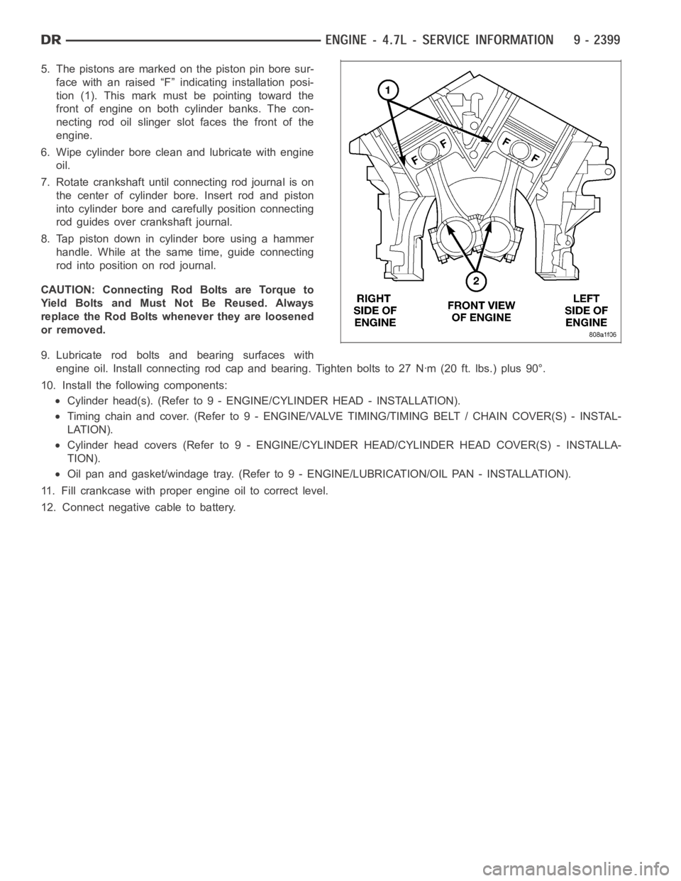
5. The pistons are marked on the piston pin bore sur-
face with an raised “F” indicating installation posi-
tion (1). This mark must be pointing toward the
front of engine on both cylinder banks. The con-
necting rod oil slinger slot faces the front of the
engine.
6. Wipe cylinder bore clean and lubricate with engine
oil.
7. Rotate crankshaft until connecting rod journal is on
the center of cylinder bore. Insert rod and piston
into cylinder bore and carefully position connecting
rod guides over crankshaft journal.
8. Tap piston down in cylinder bore using a hammer
handle. While at the same time, guide connecting
rodintopositiononrodjournal.
CAUTION: Connecting Rod Bolts are Torque to
Yield Bolts and Must Not Be Reused. Always
replace the Rod Bolts whenever they are loosened
or removed.
9. Lubricate rod bolts and bearing surfaces with
engine oil. Install connecting rod cap and bearing. Tighten bolts to 27 Nꞏm(20 ft. lbs.) plus 90°.
10. Install the following components:
Cylinder head(s). (Refer to 9 - ENGINE/CYLINDER HEAD - INSTALLATION).
Timing chain and cover. (Refer to 9 - ENGINE/VALVE TIMING/TIMING BELT / CHAIN COVER(S) - INSTAL-
LATION).
Cylinderheadcovers(Referto9-ENGINE/CYLINDER HEAD/CYLINDER HEAD COVER(S) - INSTALLA-
TION).
Oil pan and gasket/windage tray. (Refer to 9 - ENGINE/LUBRICATION/OIL PAN- INSTALLATION).
11. Fill crankcase with proper engine oil to correct level.
12. Connect negative cable to battery.
Page 1712 of 5267
DAMPER - CRANKSHAFT
REMOVAL
1. Disconnect negative cable from battery.
2. Remove accessory drive belt (Refer to 7 - COOL-
ING/ACCESSORY DRIVE/DRIVE BELTS -
REMOVAL).
3. Drain cooling system (Refer to 7 - COOLING -
STANDARD PROCEDURE).
4. Remove radiator upper hose.
5. Remove upper fan shroud.
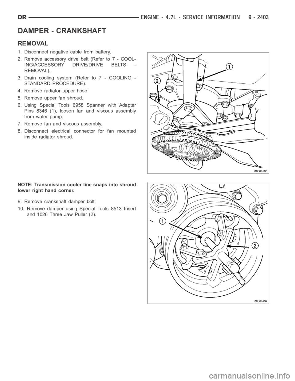
6. Using Special Tools 6958 Spanner with Adapter
Pins 8346 (1), loosen fan and viscous assembly
from water pump.
7. Remove fan and viscous assembly.
8. Disconnect electrical connector for fan mounted
inside radiator shroud.
NOTE: Transmission cooler line snaps into shroud
lower right hand corner.
9. Remove crankshaft damper bolt.
10. Remove damper using Special Tools 8513 Insert
and 1026 Three Jaw Puller (2).