Page 1734 of 5267
INSTALLATION
1. Install intake manifold gaskets.
2. Position intake manifold.
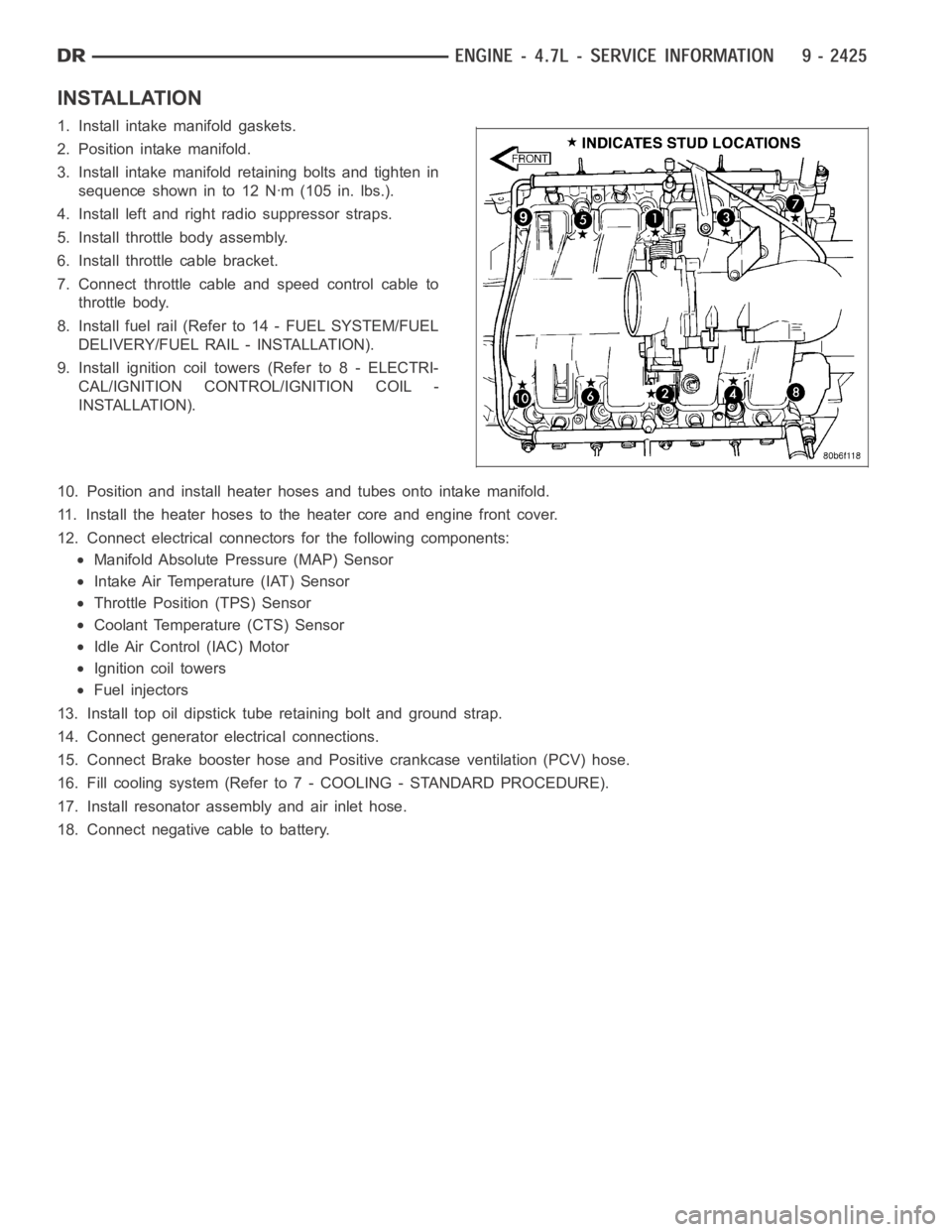
3. Install intake manifold retaining bolts and tighten in
sequence shown in to 12 Nꞏm (105 in. lbs.).
4. Install left and right radio suppressor straps.
5. Install throttle body assembly.
6. Install throttle cable bracket.
7. Connect throttle cable and speed control cable to
throttle body.
8. Install fuel rail (Refer to 14 - FUEL SYSTEM/FUEL
DELIVERY/FUEL RAIL - INSTALLATION).
9. Install ignition coil towers (Refer to 8 - ELECTRI-
CAL/IGNITION CONTROL/IGNITION COIL -
INSTALLATION).
10. Position and install heater hoses and tubes onto intake manifold.
11. Install the heater hoses to the heater core and engine front cover.
12. Connect electrical connectors for the following components:
Manifold Absolute Pressure (MAP) Sensor
Intake Air Temperature (IAT) Sensor
Throttle Position (TPS) Sensor
Coolant Temperature (CTS) Sensor
Idle Air Control (IAC) Motor
Ignition coil towers
Fuel injectors
13. Install top oil dipstick tube retaining bolt and ground strap.
14. Connect generator electrical connections.
15. Connect Brake booster hose and Positive crankcase ventilation (PCV) hose.
16. Fill cooling system (Refer to 7 - COOLING - STANDARD PROCEDURE).
17. Install resonator assembly and air inlet hose.
18. Connect negative cable to battery.
Page 1735 of 5267
MANIFOLD - EXHAUST
DESCRIPTION
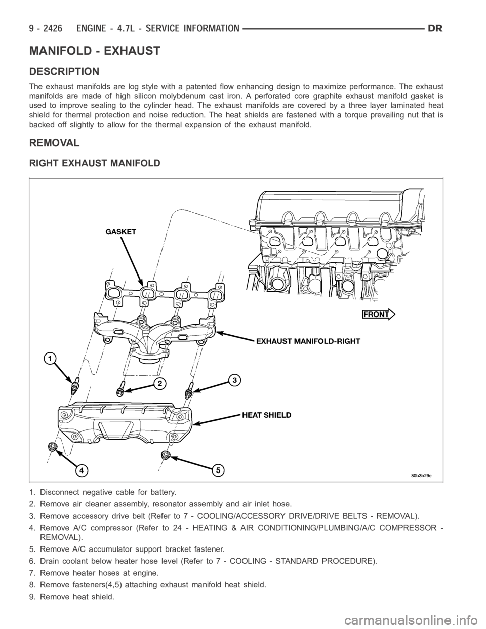
The exhaust manifolds are log style with a patented flow enhancing design to maximize performance. The exhaust
manifolds are made of high silicon molybdenum cast iron. A perforated coregraphite exhaust manifold gasket is
used to improve sealing to the cylinder head. The exhaust manifolds are covered by a three layer laminated heat
shield for thermal protection and noise reduction. The heat shields are fastened with a torque prevailing nut that is
backed off slightly to allow for the thermal expansion of the exhaust manifold.
REMOVAL
RIGHT EXHAUST MANIFOLD
1. Disconnect negative cable for battery.
2. Remove air cleaner assembly, resonator assembly and air inlet hose.
3. Remove accessory drive belt (Refer to 7 - COOLING/ACCESSORY DRIVE/DRIVE BELTS - REMOVAL).
4. Remove A/C compressor (Refer to 24 -HEATING & AIR CONDITIONING/PLUMBING/A/C COMPRESSOR -
REMOVAL).
5. Remove A/C accumulator support bracket fastener.
6. Drain coolant below heater hose level (Refer to 7 - COOLING - STANDARD PROCEDURE).
7. Remove heater hoses at engine.
8. Remove fasteners(4,5) attaching exhaust manifold heat shield.
9. Remove heat shield.
Page 1736 of 5267
10. Remove upper exhaust manifold attaching fasteners (1,3).
11. Raise vehicle on hoist.
12. Disconnect exhaust pipe from manifold.
13. Remove fasteners attaching starter. Move starter aside.
14. Remove lower exhaust manifold attaching fasteners.
15. Remove exhaust manifold and gasket. Manifold is removed from below theengine compartment.
LEFT EXHAUST MANIFOLD
1. Disconnect negative cable for battery.
2. Hoist vehicle.
3. Disconnect exhaust pipe at manifold.
4. Lower vehicle.
5. Remove the front two exhaust heat shield retaining fasteners (4,5). Raise vehicle and remove the fasteners at
rear of heat shield.
6. Remove heat shield.
7. Lower vehicle and remove the upper exhaust manifold retaining bolts (2).
8. Raise vehicle and remove the lower exhaust manifold retaining bolts (3).
9. Remove exhaust manifold and gasket. Manifold is removed from below the engine compartment.
Page 1738 of 5267
7. Connect heater hoses at engine.
8. Install fastener attaching A/C accumulator.
9. Install A/C compressor and fasteners.
10. Install accessory drive belt (Refer to 7 - COOLING/ACCESSORY DRIVE/DRIVE BELTS - INSTALLATION).
11. Install air cleaner assembly, resonator assembly and air inlet hose.
12. Install battery and connect cables.
13. Fill cooling system (Refer to 7 - COOLING - STANDARD PROCEDURE).
LEFT EXHAUST MANIFOLD
1. Install exhaust manifold and gasket from below engine compartment.
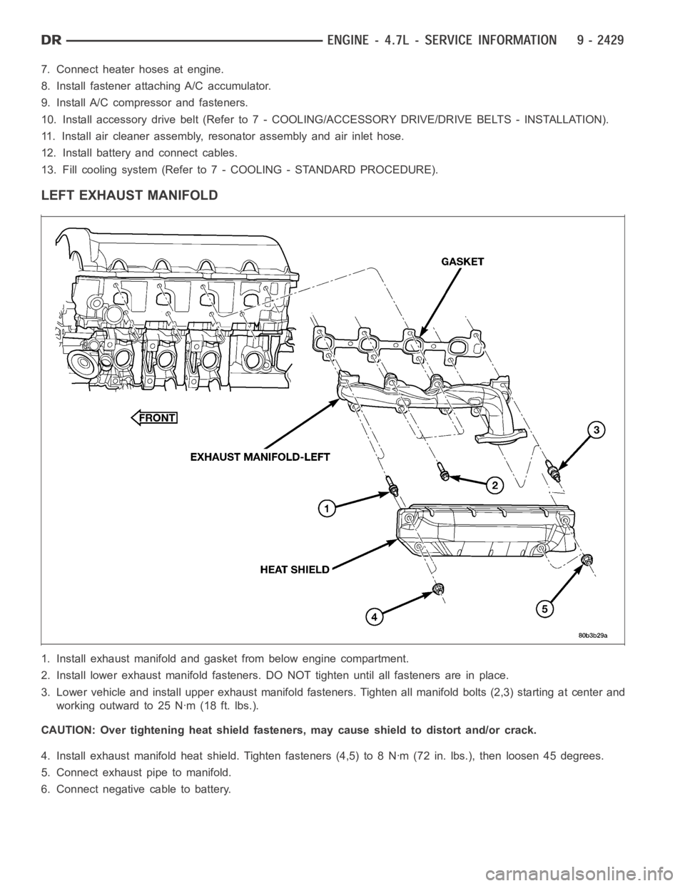
2. Install lower exhaust manifold fasteners. DO NOT tighten until all fastenersareinplace.
3. Lower vehicle and install upper exhaust manifold fasteners. Tighten all manifold bolts (2,3) starting at center and
working outward to 25 Nꞏm (18 ft. lbs.).
CAUTION: Over tightening heat shield fasteners, may cause shield to distort and/or crack.
4. Install exhaust manifold heat shield. Tighten fasteners (4,5) to 8 Nꞏm (72 in. lbs.), then loosen 45 degrees.
5. Connect exhaust pipe to manifold.
6. Connect negative cable to battery.
Page 1745 of 5267
COVER - TIMING
REMOVAL
1. Disconnect the battery negative cable.
2. Drain cooling system (Refer to 7 - COOLING -
STANDARD PROCEDURE).
3. Disconnect both heater hoses at timing cover.
4. Disconnect lower radiator hose at engine.
5. Remove crankshaft damper (Refer to 9 - ENGINE/
ENGINE BLOCK/VIBRATION DAMPER -
REMOVAL).
6. Remove accessory drive belt tensioner assembly
(1).
7. Remove the generator and A/C compressor.
CAUTION:The4.7LengineusesanRTVsealer
instead of a gasket to seal the front cover to the
engine block, from the factory. For service, Mopar
Grey Engine RTV sealant must be substituted.
NOTE: It is not necessary to remove the water
pump for timing cover removal.
8. Remove the bolts holding the timing cover to
engine block.
9. Remove cover.
Page 1746 of 5267
INSTALLATION
CAUTION: Do not use oil based liquids to clean
timing cover or block surfaces. Use only rubbing
alcohol, along with plastic or wooden scrapers.
Use no wire brushes or abrasive wheels or metal
scrapers, or damage to surfaces could result.
1. Clean timing chain cover and block surface using
rubbing alcohol.
CAUTION: The 4.7L can use a special RTV sealer
instead of a carrier gasket to seal the timing cover
to the engine block, from the factory. For service
repairs, Mopar
Grey Engine RTV must be used as
a substitute, if RTV is present. If the front cover
being used has no provisions for the water pas-
sage o-rings, then Mopar
Grey Engine RTV must
be applied around the water passages.
2. Inspect the water passage o-rings, if equipped for
any damage, and replace as necessary.
3. Apply Mopar
Grey Engine RTV sealer to the front
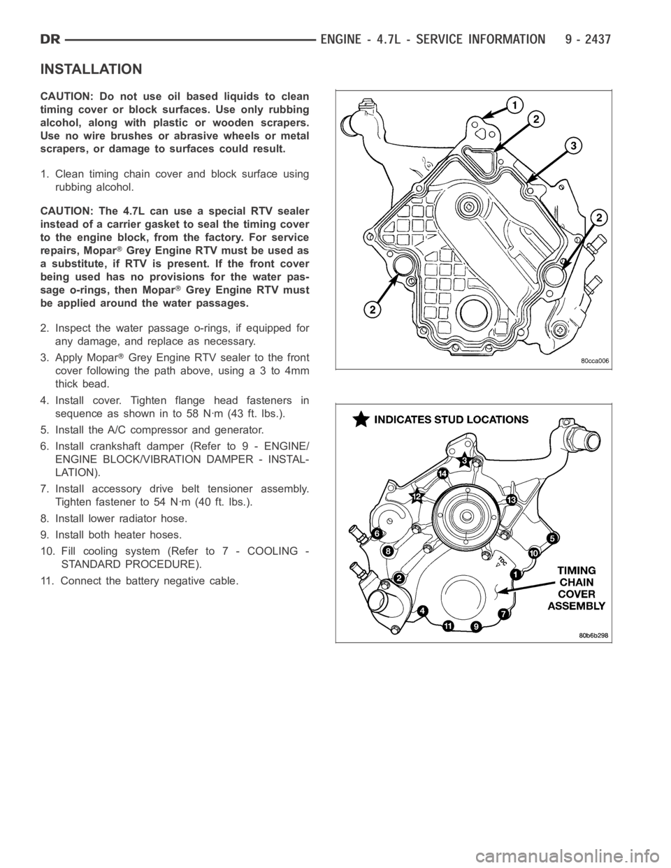
cover following the path above, using a 3 to 4mm
thick bead.
4. Install cover. Tighten flange head fasteners in
sequence as shown in to 58 Nꞏm (43 ft. lbs.).
5. Install the A/C compressor and generator.
6. Install crankshaft damper (Refer to 9 - ENGINE/
ENGINE BLOCK/VIBRATION DAMPER - INSTAL-
LATION).
7. Install accessory drive belt tensioner assembly.
Tighten fastener to 54 Nꞏm (40 ft. lbs.).
8. Install lower radiator hose.
9. Install both heater hoses.
10. Fill cooling system (Refer to 7 - COOLING -
STANDARD PROCEDURE).
11. Connect the battery negative cable.
Page 1747 of 5267
TIMING CHAIN & SPROCKETS
REMOVAL
1. Disconnect negative cable from battery.
2. Drain cooling system (Refer to 7 - COOLING -
STANDARD PROCEDURE).
3. Remove right and left cylinder head covers (Refer
to 9 - ENGINE/CYLINDER HEAD/CYLINDER
HEAD COVER(S) - REMOVAL).
4. Remove radiator fan shroud.
5. Rotate engine until timing mark (2) on crankshaft
damper aligns with TDC mark on timing chain
cover (2) (#1 cylinder exhaust stroke) and the cam-
shaft sprocket “V8” marks are at the 12 o’clock
position (1,2).
Page 1749 of 5267
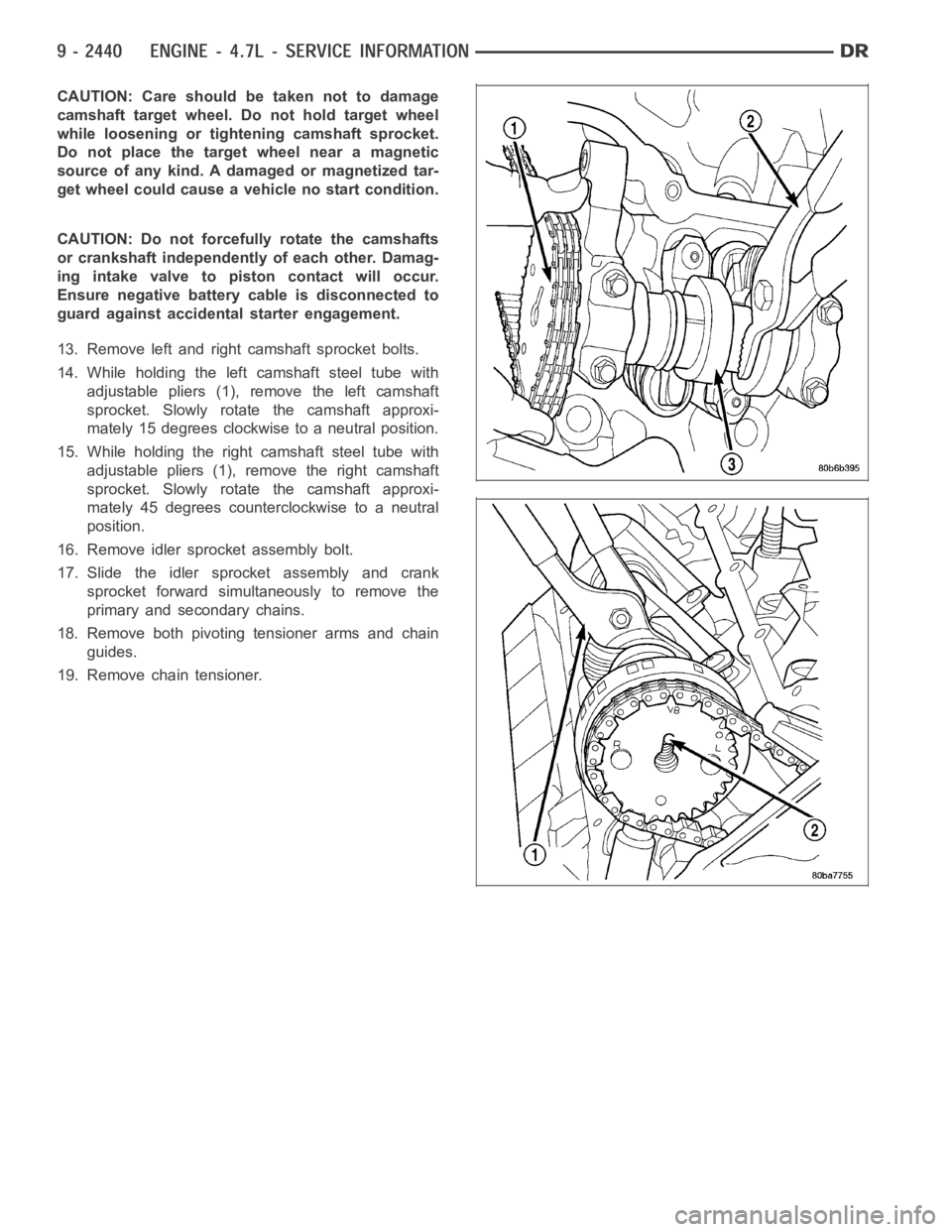
CAUTION: Care should be taken not to damage
camshaft target wheel. Do not hold target wheel
while loosening or tightening camshaft sprocket.
Do not place the target wheel near a magnetic
source of any kind. A damaged or magnetized tar-
get wheel could cause a vehicle no start condition.
CAUTION: Do not forcefully rotate the camshafts
or crankshaft independently of each other. Damag-
ing intake valve to piston contact will occur.
Ensure negative battery cable is disconnected to
guard against accidental starter engagement.
13. Remove left and right camshaft sprocket bolts.
14. While holding the left camshaft steel tube with
adjustable pliers (1), remove the left camshaft
sprocket. Slowly rotate the camshaft approxi-
mately 15 degrees clockwise to a neutral position.
15. While holding the right camshaft steel tube with
adjustable pliers (1), remove the right camshaft
sprocket. Slowly rotate the camshaft approxi-
mately 45 degrees counterclockwise to a neutral
position.
16. Remove idler sprocket assembly bolt.
17. Slide the idler sprocket assembly and crank
sprocket forward simultaneously to remove the
primary and secondary chains.
18. Remove both pivoting tensioner arms and chain
guides.
19. Remove chain tensioner.