Page 1754 of 5267
27. Install power steering pump (Referto19-STEERING/PUMP-INSTALLATION).
28. Install radiator fan shroud.
29. Fill cooling system (Refer to 7 - COOLING - STANDARD PROCEDURE).
30. Connect negative cable to battery.
Page 1758 of 5267

ENGINE - 5.7L - SERVICE INFORMATION
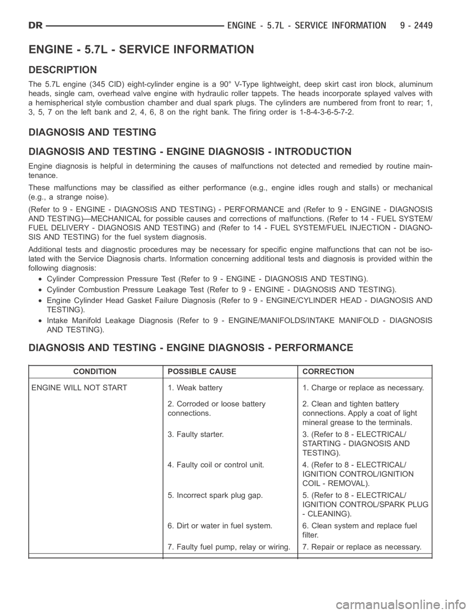
DESCRIPTION
The 5.7L engine (345 CID) eight-cylinder engine is a 90° V-Type lightweight, deep skirt cast iron block, aluminum
heads, single cam, overhead valve engine with hydraulic roller tappets. The heads incorporate splayed valves with
a hemispherical style combustion chamber and dual spark plugs. The cylinders are numbered from front to rear; 1,
3, 5, 7 on the left bank and 2, 4, 6, 8 on the right bank. The firing order is 1-8-4-3-6-5-7-2.
DIAGNOSIS AND TESTING
DIAGNOSIS AND TESTING - ENGINE DIAGNOSIS - INTRODUCTION
Engine diagnosis is helpful in determining the causes of malfunctions notdetected and remedied by routine main-
tenance.
These malfunctions may be classified as either performance (e.g., engineidles rough and stalls) or mechanical
(e.g., a strange noise).
(Refer to 9 - ENGINE - DIAGNOSIS AND TESTING) - PERFORMANCE and (Refer to 9 - ENGINE - DIAGNOSIS
AND TESTING)—MECHANICAL for possible causes and corrections of malfunctions. (Refer to 14 - FUEL SYSTEM/
FUEL DELIVERY - DIAGNOSIS AND TESTING) and (Refer to 14 - FUEL SYSTEM/FUEL INJECTION - DIAGNO-
SIS AND TESTING) for the fuel system diagnosis.
Additional tests and diagnostic procedures may be necessary for specificengine malfunctions that can not be iso-
lated with the Service Diagnosis charts. Information concerning additional tests and diagnosis is provided within the
following diagnosis:
Cylinder Compression Pressure Test (Refer to 9 - ENGINE - DIAGNOSIS AND TESTING).
Cylinder Combustion Pressure LeakageTest (Refer to 9 - ENGINE - DIAGNOSISAND TESTING).
Engine Cylinder Head Gasket Failure Diagnosis (Refer to 9 - ENGINE/CYLINDER HEAD - DIAGNOSIS AND
TESTING).
Intake Manifold Leakage Diagnosis (Refer to 9 - ENGINE/MANIFOLDS/INTAKEMANIFOLD - DIAGNOSIS
AND TESTING).
DIAGNOSIS AND TESTING - ENGINE DIAGNOSIS - PERFORMANCE
CONDITION POSSIBLE CAUSE CORRECTION
ENGINE WILL NOT START 1. Weak battery 1. Charge or replace as necessary.
2. Corroded or loose battery
connections.2. Clean and tighten battery
connections. Apply a coat of light
mineral grease to the terminals.
3. Faulty starter. 3. (Refer to 8 - ELECTRICAL/
STARTING - DIAGNOSIS AND
TESTING).
4. Faulty coil or control unit. 4. (Refer to 8 - ELECTRICAL/
IGNITION CONTROL/IGNITION
COIL - REMOVAL).
5. Incorrect spark plug gap. 5. (Refer to 8 - ELECTRICAL/
IGNITION CONTROL/SPARK PLUG
- CLEANING).
6. Dirt or water in fuel system. 6. Clean system and replace fuel
filter.
7. Faulty fuel pump, relay or wiring. 7. Repair or replace as necessary.
Page 1761 of 5267

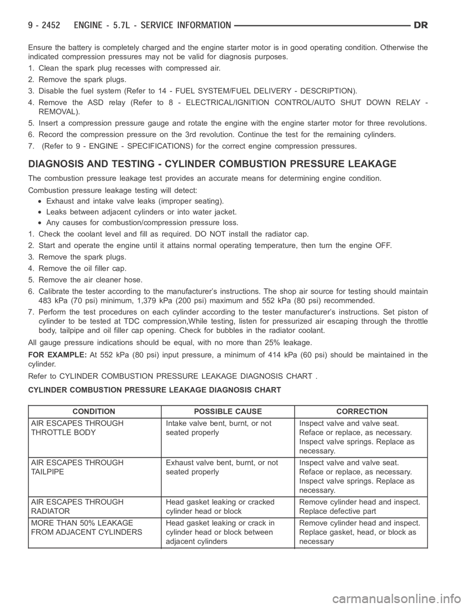
Ensurethebatteryiscompletelychargedandtheenginestartermotorisingood operating condition. Otherwise the
indicated compression pressures may not be valid for diagnosis purposes.
1. Clean the spark plug recesses with compressed air.
2. Remove the spark plugs.
3. Disable the fuel system (Refer to 14 - FUEL SYSTEM/FUEL DELIVERY - DESCRIPTION).
4. Remove the ASD relay (Refer to 8 - ELECTRICAL/IGNITION CONTROL/AUTO SHUTDOWNRELAY-
REMOVAL).
5. Insert a compression pressure gauge and rotate the engine with the engine starter motor for three revolutions.
6. Record the compression pressure on the 3rd revolution. Continue the test for the remaining cylinders.
7. (Refer to 9 - ENGINE - SPECIFICATIONS) for the correct engine compression pressures.
DIAGNOSIS AND TESTING - CYLINDERCOMBUSTION PRESSURE LEAKAGE
The combustion pressure leakage test provides an accurate means for determining engine condition.
Combustion pressure leakage testing will detect:
Exhaust and intake valve leaks (improper seating).
Leaks between adjacent cylinders or into water jacket.
Any causes for combustion/compression pressure loss.
1. Check the coolant level and fill as required. DO NOT install the radiatorcap.
2. Start and operate the engine until it attains normal operating temperature, then turn the engine OFF.
3. Remove the spark plugs.
4. Remove the oil filler cap.
5. Remove the air cleaner hose.
6. Calibrate the tester according to the manufacturer’s instructions. The shop air source for testing should maintain
483 kPa (70 psi) minimum, 1,379 kPa (200 psi) maximum and 552 kPa (80 psi) recommended.
7. Perform the test procedures on each cylinder according to the tester manufacturer’s instructions. Set piston of
cylinder to be tested at TDC compression,While testing, listen for pressurized air escaping through the throttle
body, tailpipe and oil filler cap opening. Check for bubbles in the radiator coolant.
All gauge pressure indications should be equal, with no more than 25% leakage.
FOR EXAMPLE:At 552 kPa (80 psi) input pressure, a minimum of 414 kPa (60 psi) should be maintained in the
cylinder.
Refer to CYLINDER COMBUSTION PRESSURE LEAKAGE DIAGNOSIS CHART .
CYLINDER COMBUSTION PRESSURE LEAKAGE DIAGNOSIS CHART
CONDITION POSSIBLE CAUSE CORRECTION
AIR ESCAPES THROUGH
THROTTLE BODYIntake valve bent, burnt, or not
seated properlyInspect valve and valve seat.
Reface or replace, as necessary.
Inspect valve springs. Replace as
necessary.
AIR ESCAPES THROUGH
TAILPIPEExhaust valve bent, burnt, or not
seated properlyInspect valve and valve seat.
Reface or replace, as necessary.
Inspect valve springs. Replace as
necessary.
AIR ESCAPES THROUGH
RADIATORHead gasket leaking or cracked
cylinder head or blockRemove cylinder head and inspect.
Replace defective part
MORE THAN 50% LEAKAGE
FROM ADJACENT CYLINDERSHead gasket leaking or crack in
cylinder head or block between
adjacent cylindersRemove cylinder head and inspect.
Replace gasket, head, or block as
necessary
Page 1765 of 5267

CONDITION POSSIBLE CAUSES CORRECTION
EXCESSIVE OIL CONSUMPTION
OR SPARK PLUGS OIL FOULED1. CCV System malfunction 1. (Refer to 25 - EMISSIONS
CONTROL/EVAPORATIVE
EMISSIONS - DESCRIPTION) for
correct operation
2. Defective valve stem seal(s) 2. Repair or replace seal(s)
3. Worn or broken piston rings 3. Hone cylinder bores. Install new
rings
4. Scuffed pistons/cylinder walls 4. Hone cylinder bores and replace
pistons as required
5. Carbon in oil control ring groove 5. Remove rings and de-carbon
piston
6. Worn valve guides 6. Inspect/replace valve guides as
necessary
7. Piston rings fitted too tightly in
grooves7. Remove rings and check ring end
gap and side clearance. Replace if
necessary
STANDARD PROCEDURE
STANDARD PROCEDURE - REPAIR DAMAGED OR WORN THREADS
CAUTION: Be sure that the tapped holes maintain the original center line.
Damaged or worn threads can be repaired. Essentially, this repair consistsof:
Drilling out worn or damaged threads.
Tapping the hole with a special Heli-Coil Tap, or equivalent.
Installing an insert into the tapped hole to bring the hole back to its original thread size.
STANDARD PROCEDURE—HYDROSTATIC LOCK
CAUTION: DO NOT use the starter motor to rotate the crankshaft. Severe damage could occur.
When an engine is suspected of hydrostatic lock (regardless of what causedthe problem), follow the steps below.
1. Perform the Fuel Pressure Release Procedure (Refer to 14 - FUEL SYSTEM/FUEL DELIVERY - STANDARD
PROCEDURE).
2. Disconnect the negative cable(s) from the battery.
3. Inspect air cleaner, induction system, and intake manifold to ensure system is dry and clear of foreign material.
4. Place a shop towel around the spark plugs to catch any fluid that may possibly be under pressure in the cylinder
head. Remove the spark plugs.
5. With all spark plugs removed, rotate the crankshaft using a breaker bar and socket.
6. Identify the fluid in the cylinders (coolant, fuel, oil, etc.).
7. Be sure all fluid has been removed from the cylinders.
8. Repair engine or components as necessary to prevent this problem from occurring again.
9. Squirt a small amount of engine oil into the cylinders to lubricate the walls. This will prevent damage on restart.
10. Install new spark plugs. Tighten the spark plugs to 41 Nꞏm (30 ft. lbs.) torque.
11. Drain engine oil. Remove and discard the oil filter.
12. Install the drain plug. Tighten the plug to 34 Nꞏm (25 ft. lbs.) torque.
13. Install a new oil filter.
14. Fill engine crankcase with the specified amount and grade of oil. (Refer to LUBRICATION & MAINTENANCE -
SPECIFICATIONS).
Page 1766 of 5267
15. Connect the negative cable(s) to the battery.
16. Start the engine and check for any leaks.
REMOVAL
1. Perform the Fuel System Pressure Release proce-
dure (Refer to 14 - FUEL SYSTEM/FUEL DELIV-
ERY - STANDARD PROCEDURE).
2. Disconnect the battery negative cable.
3. Remove the air cleaner resonator and duct work as
an assembly.
4. Drain cooling system (Refer to 7 - COOLING -
STANDARD PROCEDURE).
5. Remove the viscous fan/drive (Refer to 7 - COOL-
ING/ENGINE/RADIATOR FAN - REMOVAL).
6. Remove the accessory drive belt (Refer to 7 -
COOLING/ACCESSORY DRIVE/DRIVE BELTS -
REMOVAL).
7. Remove the fan shroud (3).
Page 1776 of 5267

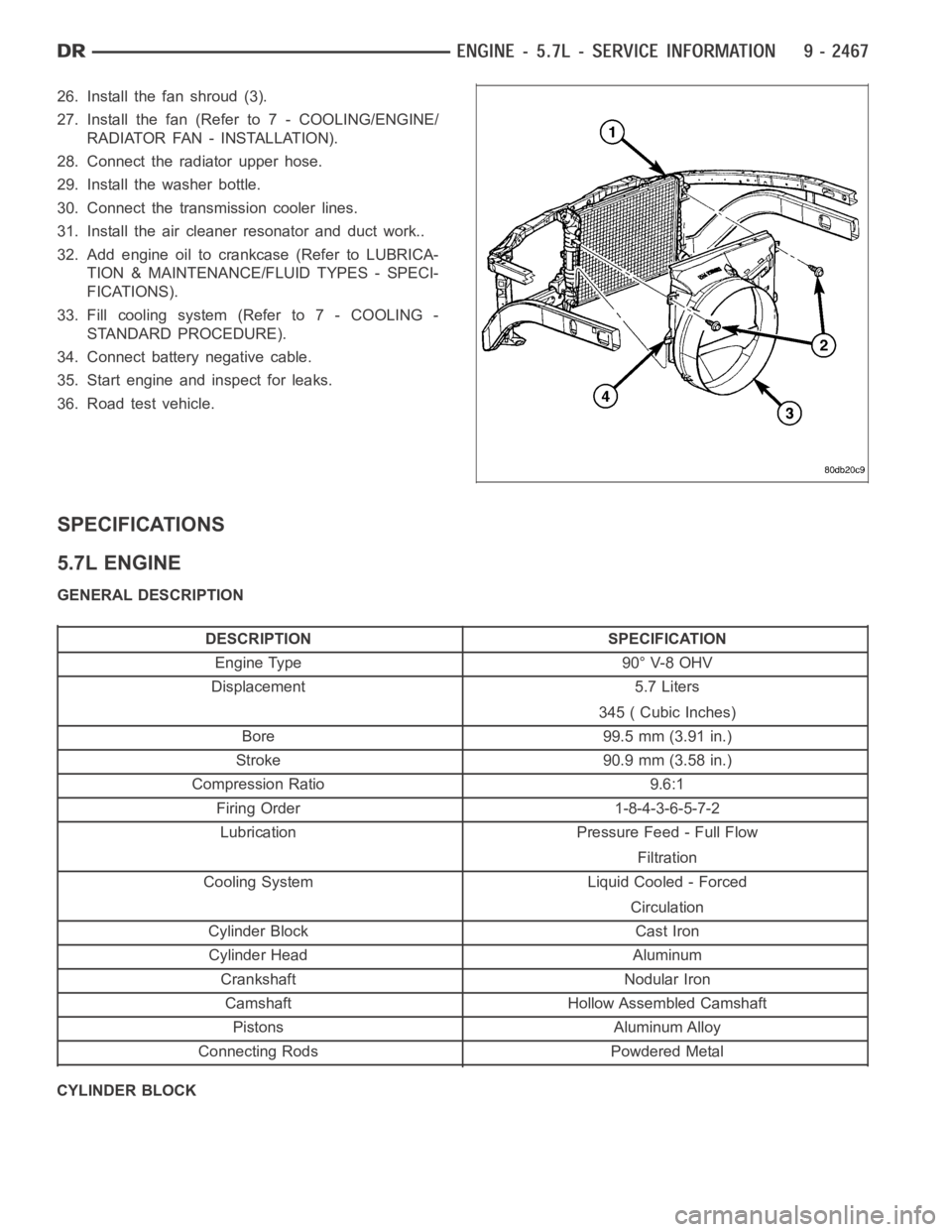
26. Install the fan shroud (3).
27. Install the fan (Refer to 7 - COOLING/ENGINE/
RADIATOR FAN - INSTALLATION).
28. Connect the radiator upper hose.
29. Install the washer bottle.
30. Connect the transmission cooler lines.
31. Install the air cleaner resonator and duct work..
32. Add engine oil to crankcase (Refer to LUBRICA-
TION & MAINTENANCE/FLUID TYPES - SPECI-
FICATIONS).
33. Fill cooling system (Refer to 7 - COOLING -
STANDARD PROCEDURE).
34. Connect battery negative cable.
35. Start engine and inspect for leaks.
36. Road test vehicle.
SPECIFICATIONS
5.7L ENGINE
GENERAL DESCRIPTION
DESCRIPTION SPECIFICATION
Engine Type 90° V-8 OHV
Displacement 5.7 Liters
345 ( Cubic Inches)
Bore 99.5 mm (3.91 in.)
Stroke 90.9 mm (3.58 in.)
Compression Ratio 9.6:1
Firing Order 1-8-4-3-6-5-7-2
Lubrication Pressure Feed - Full Flow
Filtration
Cooling System Liquid Cooled - Forced
Circulation
Cylinder Block Cast Iron
Cylinder Head Aluminum
Crankshaft Nodular Iron
Camshaft Hollow Assembled Camshaft
Pistons Aluminum Alloy
Connecting Rods Powdered Metal
CYLINDER BLOCK
Page 1792 of 5267

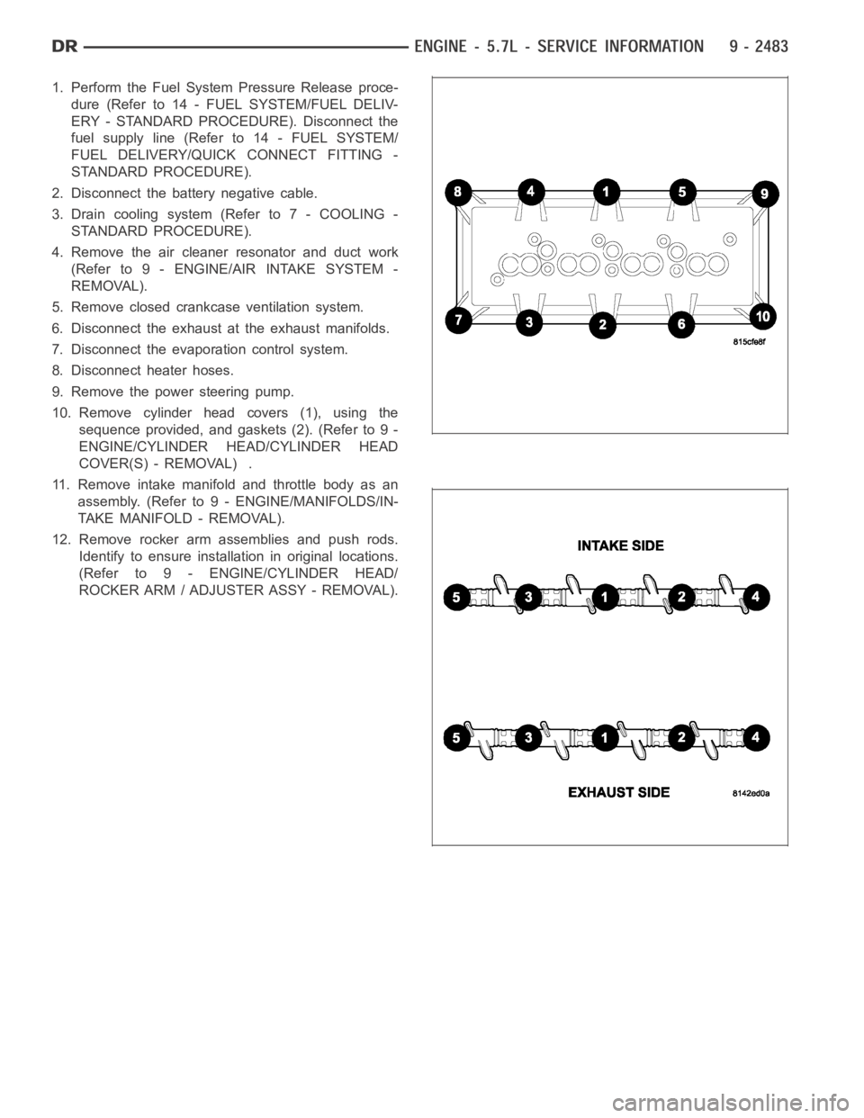
1. Perform the Fuel System Pressure Release proce-
dure (Refer to 14 - FUEL SYSTEM/FUEL DELIV-
ERY - STANDARD PROCEDURE). Disconnect the
fuelsupplyline(Referto14-FUELSYSTEM/
FUEL DELIVERY/QUICK CONNECT FITTING -
STANDARD PROCEDURE).
2. Disconnect the battery negative cable.
3. Drain cooling system (Refer to 7 - COOLING -
STANDARD PROCEDURE).
4. Remove the air cleaner resonator and duct work
(Refer to 9 - ENGINE/AIR INTAKE SYSTEM -
REMOVAL).
5. Remove closed crankcase ventilation system.
6. Disconnect the exhaust at the exhaust manifolds.
7. Disconnect the evaporation control system.
8. Disconnect heater hoses.
9. Remove the power steering pump.
10. Remove cylinder head covers (1), using the
sequence provided, and gaskets (2). (Refer to 9 -
ENGINE/CYLINDER HEAD/CYLINDER HEAD
COVER(S) - REMOVAL) .
11. Remove intake manifold and throttle body as an
assembly. (Refer to 9 - ENGINE/MANIFOLDS/IN-
TAKE MANIFOLD - REMOVAL).
12. Remove rocker arm assemblies and push rods.
Identify to ensure installation in original locations.
(Refer to 9 - ENGINE/CYLINDER HEAD/
ROCKER ARM / ADJUSTER ASSY - REMOVAL).
Page 1798 of 5267
13. Install cylinder head covers (1) (Refer to 9 -
ENGINE/CYLINDER HEAD/CYLINDER HEAD
COVER(S) - INSTALLATION).
14. Connect the evaporation control system.
15. Install the air cleaner (Refer to 9 - ENGINE/AIR
INTAKE SYSTEM - INSTALLATION).
16. Fill cooling system (Refer to 7 - COOLING -
STANDARD PROCEDURE).
17. Connect the negative cable to the battery.
18. Start engine check for leaks.