2006 DODGE RAM SRT-10 change wheel
[x] Cancel search: change wheelPage 4222 of 5267
TRANSFER CASE - NV244 GENII - SERVICE INFORMATION
DESCRIPTION
The NV244 GENII is an electronically controlled full and part-time transfer case with no two wheel drive operation.
A differential in the transfer case is used to control torque transfer to the front and rear axles. A low range gear
reduction system provides increased low speed torque capability for off road operation. The low range provides a
2.72:1 reduction ratio.
The geartrain is mounted in two aluminum case halves attached with bolts. The mainshaft front and rear bearings
are mounted in aluminum retainer housings bolted to the case halves.
OPERATING RANGES
NV244 GENII operating ranges are:
AWD (All-Wheel Drive).
4LOCK (Part-time).
4LO.
NEUTRAL.
The AWD mode can be used at any time and on any road surface.
The 4LOCK (Part-time) and 4LO ranges are for off road use only. The only timetheserangescanbeusediswhen
the road surface is covered with snow, ice, or other loose slippery material.
SHIFT MECHANISM
Operating ranges are selected with a dash mounted shift selector switch. The shift selector switch provides a input
to the Front Control Module (FCM) to indicate the driver’s desire to changeoperating ranges. The FCM uses this
input, along with the input from the transfer case mounted mode sensor and information from the vehicle’s bus, to
determine if a shift is permitted. If the FCM decides the shift is permitted, the FCM controls the shift motor, mounted
to the exterior of the transfer case, to perform the shift.
IDENTIFICATION
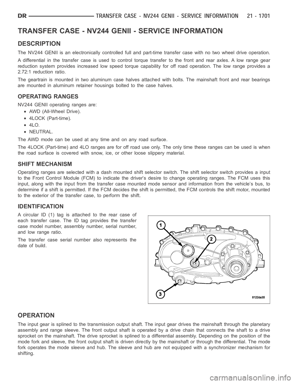
A circular ID (1) tag is attached to the rear case of
each transfer case. The ID tag provides the transfer
case model number, assembly number, serial number,
and low range ratio.
The transfer case serial number also represents the
date of build.
OPERATION
The input gear is splined to the transmission output shaft. The input gear drives the mainshaft through the planetary
assembly and range sleeve. The front output shaft is operated by a drive chain that connects the shaft to a drive
sprocket on the mainshaft. The drive sprocket is splined to a differentialassembly. Depending on the position of the
mode fork and sleeve, the front output shaft is driven directly by the mainshaft or through the differential. The mode
fork operates the mode sleeve and hub. The sleeve and hub are not equipped with a synchronizer mechanism for
shifting.
Page 4265 of 5267
TRANSFER CASE - NV273 - SERVICE INFORMATION
DESCRIPTION
The NV273 is an electronically controlled part-time transfer case with a low range gear reduction system. The
NV273 has three operating ranges plus a NEUTRAL position. The low range system provides a gear reduction ratio
for increased low speed torque capability.
The geartrain is mounted in two aluminum case halves attached with bolts. The mainshaft front and rear bearings
are mounted in aluminum case halves.
OPERATING RANGES
Transfer case operating ranges are:
2WD (2-wheel drive).
4HI (4-wheel drive).
4LO (4-wheel drive low range).
NEUTRAL.
The 2WD range is for use on any road surface at any time.
The 4HI and 4LO ranges are for off road use only. They are not for use on hard surface roads. The only exception
being when the road surface is wet or slippery or covered by ice and snow.
The low range reduction gear system is operative in 4LO range only. This range is for extra pulling power in off road
situations. Low range reduction ratio is 2.72:1.
SHIFT MECHANISM
Operating ranges are selected with a dash mounted shift selector switch. The shift selector switch provides a input
to the Transfer Case Control Module (TCCM) to indicate the driver’s desireto change operating ranges. The TCCM
uses this input, along with input from the transfer case mounted mode sensor and information from the vehicle’s
bus, to determine if a shift is permitted. If the TCCM decides the shift is permitted, the TCCM controls the shift
motor, mounted to the exterior of the transfer case, to perform the shift.
IDENTIFICATION
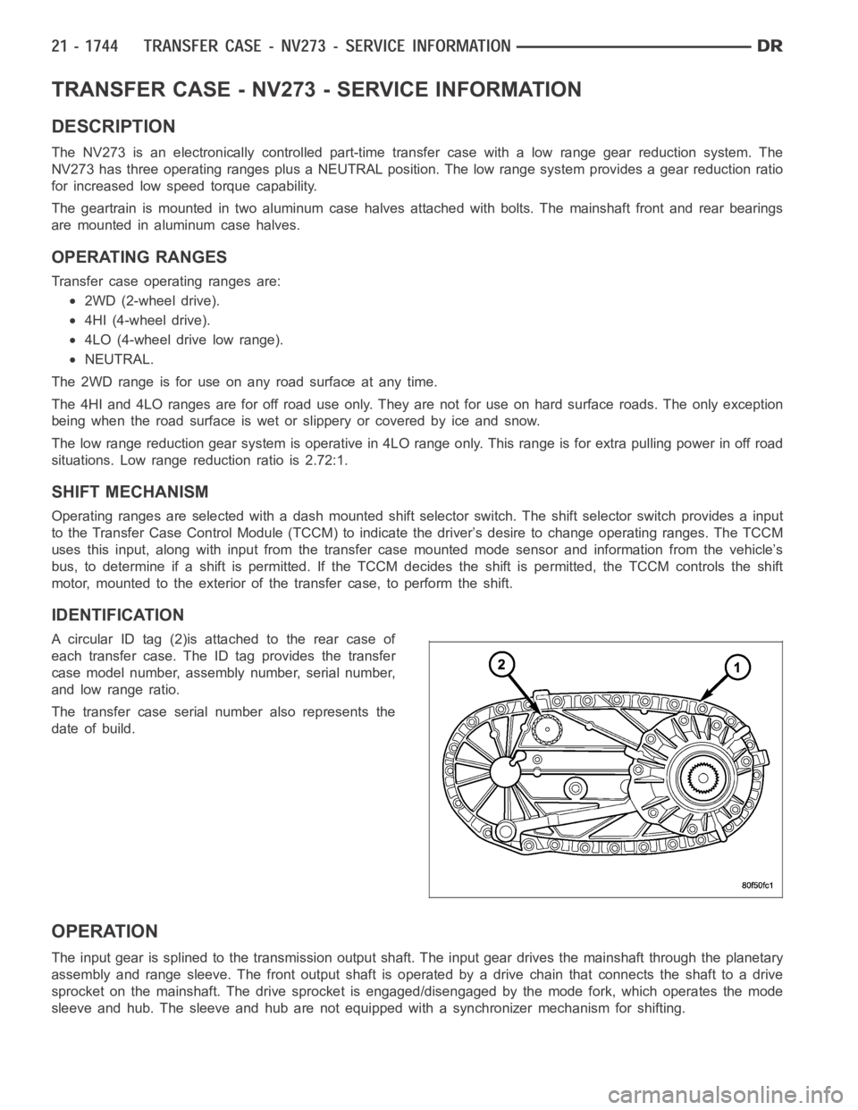
A circular ID tag (2)is attached to the rear case of
each transfer case. The ID tag provides the transfer
case model number, assembly number, serial number,
and low range ratio.
The transfer case serial number also represents the
date of build.
OPERATION
The input gear is splined to the transmission output shaft. The input gear drives the mainshaft through the planetary
assembly and range sleeve. The front output shaft is operated by a drive chain that connects the shaft to a drive
sprocket on the mainshaft. The drive sprocket is engaged/disengaged by themodefork,whichoperatesthemode
sleeve and hub. The sleeve and hub are not equipped with a synchronizer mechanism for shifting.
Page 4323 of 5267
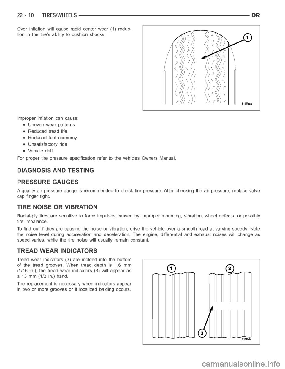
Over inflation will cause rapid center wear (1) reduc-
tion in the tire’s ability to cushion shocks.
Improper inflation can cause:
Uneven wear patterns
Reduced tread life
Reduced fuel economy
Unsatisfactory ride
Vehicle drift
For proper tire pressure specification refer to the vehicles Owners Manual.
DIAGNOSIS AND TESTING
PRESSURE GAUGES
A quality air pressure gauge is recommended to check tire pressure. After checking the air pressure, replace valve
cap finger tight.
TIRE NOISE OR VIBRATION
Radial-ply tires are sensitive to force impulses caused by improper mounting, vibration, wheel defects, or possibly
tire imbalance.
To find out if tires are causing the noise or vibration, drive the vehicle over a smooth road at varying speeds. Note
the noise level during acceleration and deceleration. The engine, differential and exhaust noises will change as
speed varies, while the tire noise will usually remain constant.
TREAD WEAR INDICATORS
Tread wear indicators (3) are molded into the bottom
of the tread grooves. When tread depth is 1.6 mm
(1/16 in.), the tread wear indicators (3) will appear as
a 13 mm (1/2 in.) band.
Tire replacement is necessary when indicators appear
in two or more grooves or if localized balding occurs.
Page 4559 of 5267
SEATS
WARNING
WARNINGS - RESTRAINT SYSTEM
WARNING: To avoid personal injury or death, during and following any seat beltorchildrestraintanchor
service, carefully inspect all seat belts, buckles, mounting hardware, retractors, tether straps, and anchors
for proper installation, operation, or damage. Replace any belt that is cut, frayed, or torn. Straighten any
belt that is twisted. Tighten any loose fasteners. Replace any belt that has a damaged or ineffective buckle
or retractor. Replace any belt that has a bent or damaged latch plate or anchor plate. Replace any child
restraint anchor or the unit to which the anchor is integral that has been bent or damaged. Never attempt to
repair a seat belt or child restraint component. Always replace damaged orineffective seat belt and child
restraint components with the correct, new and unused replacement parts listed in the DaimlerChrysler
Mopar
Parts Catalog.
WARNING: To avoid personal injury or death, on vehicles equipped with airbags, disable the supplemental
restraint system before attempting any steering wheel, steering column,airbag, seat belt tensioner, impact
sensor, or instrument panel component diagnosis or service. Disconnect and isolate the battery negative
(ground) cable, then wait two minutes for the system capacitor to discharge before performing further diag-
nosis or service. This is the only sure way to disable the supplemental restraint system. Failure to take the
proper precautions could result in accidental airbag deployment.
WARNING: To avoid personal injury or death on vehicles equipped with airbags, before performing any
welding operations disconnect and isolate the battery negative (ground)cable and disconnect all wire har-
ness connectors from the Occupant Restraint Controller (ORC). Failure totake the proper precautions could
result in accidental airbag deployment and other possible damage to the supplemental restraint system cir-
cuits and components.
WARNING: To avoid personal injury or death, do not attempt to dismantle an airbag unit or tamper with its
inflator. Do not puncture, incinerate, or bring into contact with electricity. Do not store at temperatures
exceeding 93° C (200° F). An airbag inflator unit may contain sodium azide and potassium nitrate. These
materials are poisonous and extremely flammable. Contact with acid, water, or heavy metals may produce
harmful and irritating gases (sodium hydroxide is formed in the presence of moisture) or combustible com-
pounds. An airbag inflator unit may also contain a gas canister pressurizedtoover2500psi.
WARNING: To avoid personal injury or death, when handling a seat belt tensioner retractor, proper care
should be exercised to keep fingers out from under the retractor cover and away from the seat belt webbing
where it exits from the retractor cover.
WARNING: To avoid personal injury or death, replace all restraint system components only with parts spec-
ified in the DaimlerChrysler Mopar
Parts Catalog. Substitute parts may appear interchangeable, but internal
differences may result in inferior occupant protection.
WARNING: To avoid personal injury or death, the fasteners, screws, and bolts originally used for the
restraint system components must never be replaced with any substitutes.These fasteners have special
coatings and are specifically designed for the restraint system. Any timea new fastener is needed, replace
it with the correct fasteners provided in the service package or specifiedin the DaimlerChrysler Mopar
Parts Catalog.
WARNING: To avoid personal injury or death, when a steering column has an airbag unit attached, never
place the column on the floor or any other surface with the steering wheel orairbag unit face down.
Page 5086 of 5267
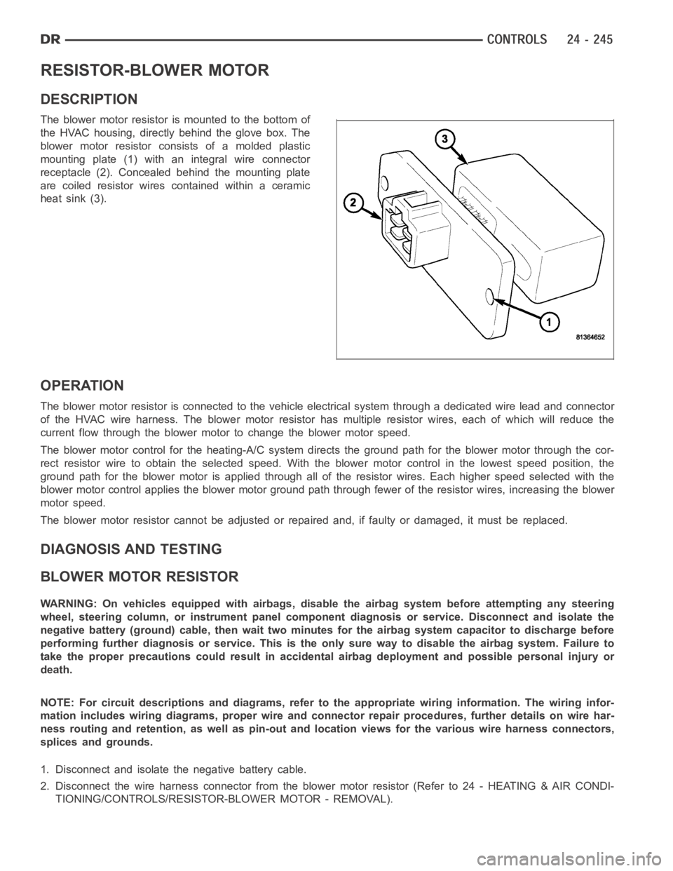
RESISTOR-BLOWER MOTOR
DESCRIPTION
The blower motor resistor is mounted to the bottom of
the HVAC housing, directly behind the glove box. The
blower motor resistor consists of a molded plastic
mounting plate (1) with an integral wire connector
receptacle (2). Concealed behind the mounting plate
are coiled resistor wires contained within a ceramic
heat sink (3).
OPERATION
The blower motor resistor is connected to the vehicle electrical system through a dedicated wire lead and connector
of the HVAC wire harness. The blower motor resistor has multiple resistor wires, each of which will reduce the
current flow through the blower motor to change the blower motor speed.
The blower motor control for the heating-A/C system directs the ground path for the blower motor through the cor-
rect resistor wire to obtain the selected speed. With the blower motor control in the lowest speed position, the
ground path for the blower motor is applied through all of the resistor wires. Each higher speed selected with the
blower motor control applies the blower motor ground path through fewer ofthe resistor wires, increasing the blower
motor speed.
The blower motor resistor cannot be adjusted or repaired and, if faulty or damaged, it must be replaced.
DIAGNOSIS AND TESTING
BLOWER MOTOR RESISTOR
WARNING: On vehicles equipped with airbags, disable the airbag system before attempting any steering
wheel, steering column, or instrument panel component diagnosis or service. Disconnect and isolate the
negative battery (ground) cable, then wait two minutes for the airbag system capacitor to discharge before
performing further diagnosis or service. This is the only sure way to disable the airbag system. Failure to
take the proper precautions could result in accidental airbag deploymentand possible personal injury or
death.
NOTE: For circuit descriptions and diagrams, refer to the appropriate wiring information. The wiring infor-
mation includes wiring diagrams, proper wire and connector repair procedures, further details on wire har-
ness routing and retention, as well as pin-out and location views for the various wire harness connectors,
splices and grounds.
1. Disconnect and isolate the negative battery cable.
2. Disconnect the wire harness connector from the blower motor resistor (Refer to 24 - HEATING & AIR CONDI-
TIONING/CONTROLS/RESISTOR-BLOWER MOTOR - REMOVAL).
Page 5151 of 5267
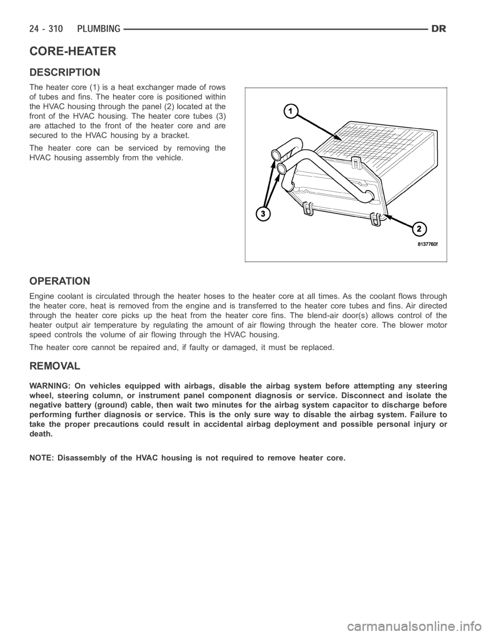
CORE-HEATER
DESCRIPTION
The heater core (1) is a heat exchanger made of rows
of tubes and fins. The heater core is positioned within
the HVAC housing through the panel (2) located at the
front of the HVAC housing. The heater core tubes (3)
are attached to the front of the heater core and are
secured to the HVAC housing by a bracket.
The heater core can be serviced by removing the
HVAC housing assembly from the vehicle.
OPERATION
Engine coolant is circulated through the heater hoses to the heater core atall times. As the coolant flows through
the heater core, heat is removed from the engine and is transferred to the heater core tubes and fins. Air directed
through the heater core picks up the heat from the heater core fins. The blend-air door(s) allows control of the
heater output air temperature by regulating the amount of air flowing through the heater core. The blower motor
speed controls the volume of air flowing through the HVAC housing.
The heater core cannot be repaired and, if faulty or damaged, it must be replaced.
REMOVAL
WARNING: On vehicles equipped with airbags, disable the airbag system before attempting any steering
wheel, steering column, or instrument panel component diagnosis or service. Disconnect and isolate the
negative battery (ground) cable, then wait two minutes for the airbag system capacitor to discharge before
performing further diagnosis or service. This is the only sure way to disable the airbag system. Failure to
take the proper precautions could result in accidental airbag deploymentand possible personal injury or
death.
NOTE: Disassembly of the HVAC housing is not required to remove heater core.