2006 DODGE RAM SRT-10 change wheel
[x] Cancel search: change wheelPage 141 of 5267
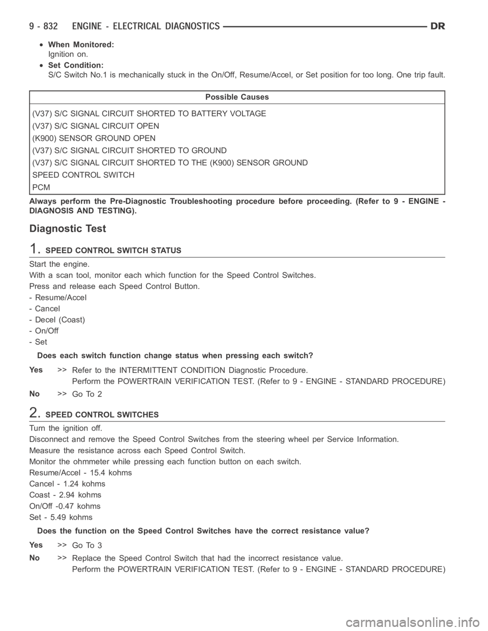
When Monitored:
Ignition on.
Set Condition:
S/C Switch No.1 is mechanically stuck in the On/Off, Resume/Accel, or Set position for too long. One trip fault.
Possible Causes
(V37) S/C SIGNAL CIRCUIT SHORTED TO BATTERY VOLTAGE
(V37) S/C SIGNAL CIRCUIT OPEN
(K900) SENSOR GROUND OPEN
(V37) S/C SIGNAL CIRCUIT SHORTED TO GROUND
(V37) S/C SIGNAL CIRCUIT SHORTED TO THE (K900) SENSOR GROUND
SPEED CONTROL SWITCH
PCM
Always perform the Pre-Diagnostic Troubleshooting procedure before proceeding. (Refer to 9 - ENGINE -
DIAGNOSIS AND TESTING).
Diagnostic Test
1.SPEED CONTROL SWITCH STATUS
Start the engine.
With a scan tool, monitor each which function for the Speed Control Switches.
Press and release each Speed Control Button.
- Resume/Accel
-Cancel
- Decel (Coast)
-On/Off
-Set
Does each switch function change status when pressing each switch?
Ye s>>
Refer to the INTERMITTENT CONDITION Diagnostic Procedure.
Perform the POWERTRAIN VERIFICATION TEST. (Refer to 9 - ENGINE - STANDARD PROCEDURE)
No>>
Go To 2
2.SPEED CONTROL SWITCHES
Turn the ignition off.
Disconnect and remove the Speed Control Switches from the steering wheel per Service Information.
Measure the resistance across each Speed Control Switch.
Monitor the ohmmeter while pressing each function button on each switch.
Resume/Accel - 15.4 kohms
Cancel - 1.24 kohms
Coast - 2.94 kohms
On/Off -0.47 kohms
Set - 5.49 kohms
Does the function on the Speed Control Switches have the correct resistance value?
Ye s>>
Go To 3
No>>
Replace the Speed Control Switch that had the incorrect resistance value.
Perform the POWERTRAIN VERIFICATION TEST. (Refer to 9 - ENGINE - STANDARD PROCEDURE)
Page 1413 of 5267
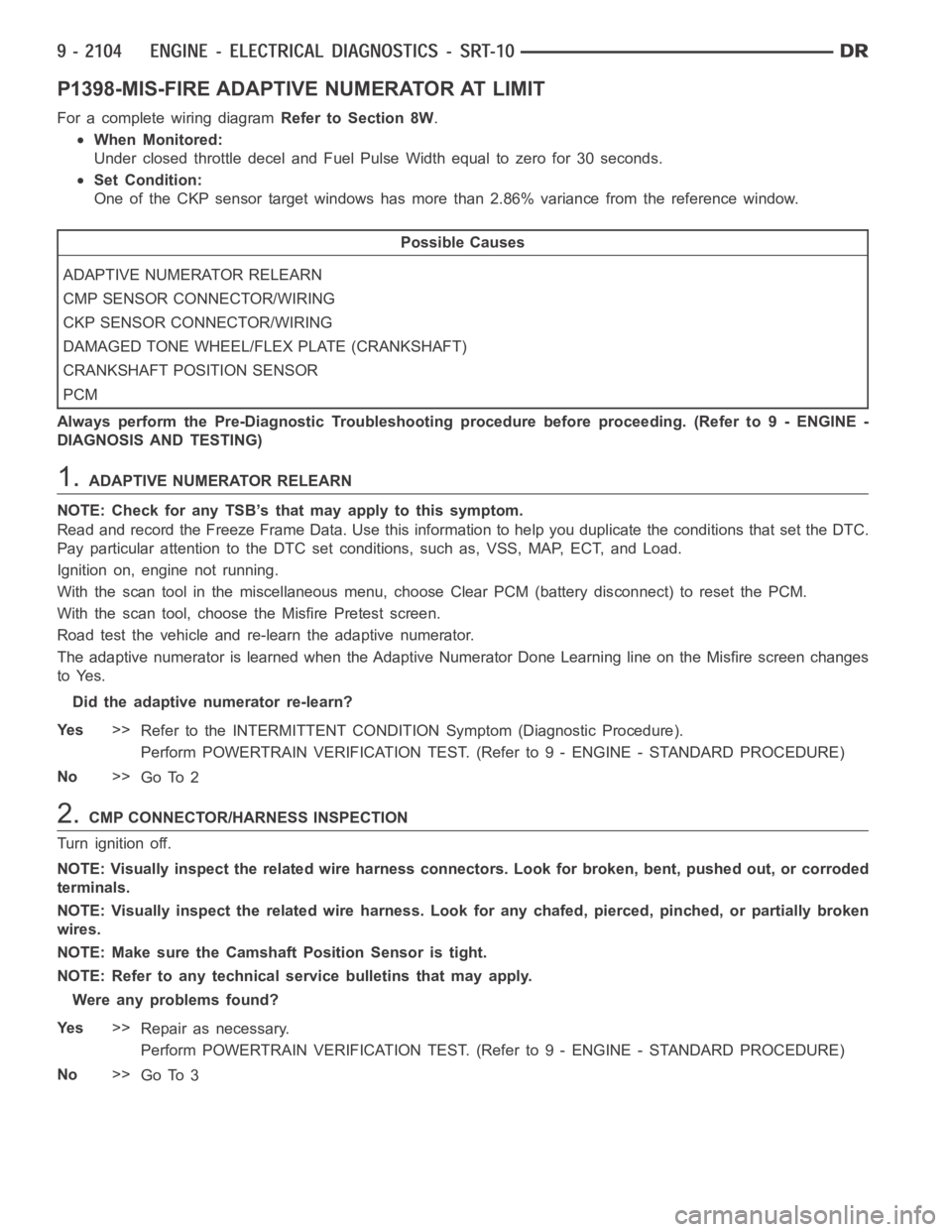
P1398-MIS-FIRE ADAPTIVE NUMERATOR AT LIMIT
For a complete wiring diagramRefer to Section 8W.
When Monitored:
Under closed throttle decel and Fuel Pulse Width equal to zero for 30 seconds.
Set Condition:
One of the CKP sensor target windows has more than 2.86% variance from the reference window.
Possible Causes
ADAPTIVE NUMERATOR RELEARN
CMP SENSOR CONNECTOR/WIRING
CKP SENSOR CONNECTOR/WIRING
DAMAGED TONE WHEEL/FLEX PLATE (CRANKSHAFT)
CRANKSHAFT POSITION SENSOR
PCM
Always perform the Pre-Diagnostic Troubleshooting procedure before proceeding. (Refer to 9 - ENGINE -
DIAGNOSIS AND TESTING)
1.ADAPTIVE NUMERATOR RELEARN
NOTE: Check for any TSB’s that may apply to this symptom.
Read and record the Freeze Frame Data. Use this information to help you duplicate the conditions that set the DTC.
Pay particular attention to the DTC set conditions, such as, VSS, MAP, ECT,and Load.
Ignition on, engine not running.
With the scan tool in the miscellaneous menu, choose Clear PCM (battery disconnect) to reset the PCM.
With the scan tool, choose the Misfire Pretest screen.
Road test the vehicle and re-learn the adaptive numerator.
The adaptive numerator is learned when the Adaptive Numerator Done Learning line on the Misfire screen changes
to Yes.
Did the adaptive numerator re-learn?
Ye s>>
Refer to the INTERMITTENT CONDITIONSymptom (Diagnostic Procedure).
Perform POWERTRAIN VERIFICATION TEST. (Refer to 9 - ENGINE - STANDARD PROCEDURE)
No>>
Go To 2
2.CMP CONNECTOR/HARNESS INSPECTION
Turn ignition off.
NOTE: Visually inspect the related wire harness connectors. Look for broken, bent, pushed out, or corroded
terminals.
NOTE: Visually inspect the related wire harness. Look for any chafed, pierced, pinched, or partially broken
wires.
NOTE: Make sure the Camshaft Position Sensor is tight.
NOTE: Refer to any technical service bulletins that may apply.
Were any problems found?
Ye s>>
Repair as necessary.
Perform POWERTRAIN VERIFICATION TEST. (Refer to 9 - ENGINE - STANDARD PROCEDURE)
No>>
Go To 3
Page 1492 of 5267
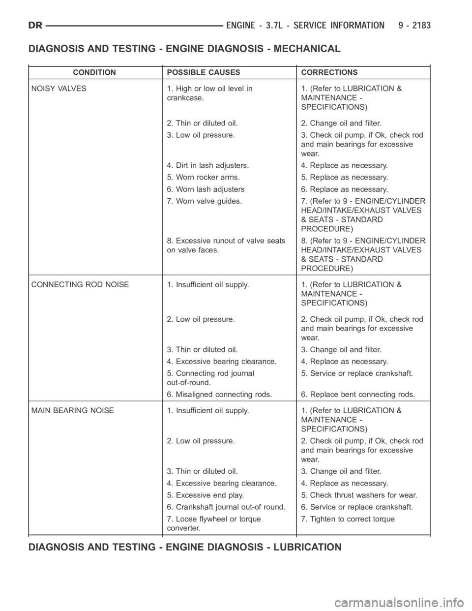
DIAGNOSIS AND TESTING - ENGINE DIAGNOSIS - MECHANICAL
CONDITION POSSIBLE CAUSES CORRECTIONS
NOISY VALVES 1. High or low oil level in
crankcase.1. (Refer to LUBRICATION &
MAINTENANCE -
SPECIFICATIONS)
2. Thin or diluted oil. 2. Change oil and filter.
3. Low oil pressure. 3. Check oil pump, if Ok, check rod
and main bearings for excessive
wear.
4. Dirt in lash adjusters. 4. Replace as necessary.
5. Worn rocker arms. 5. Replace as necessary.
6. Worn lash adjusters 6. Replace as necessary.
7. Worn valve guides. 7. (Refer to 9 - ENGINE/CYLINDER
HEAD/INTAKE/EXHAUST VALVES
& SEATS - STANDARD
PROCEDURE)
8. Excessive runout of valve seats
on valve faces.8. (Refer to 9 - ENGINE/CYLINDER
HEAD/INTAKE/EXHAUST VALVES
& SEATS - STANDARD
PROCEDURE)
CONNECTING ROD NOISE 1. Insufficient oil supply. 1. (Refer to LUBRICATION&
MAINTENANCE -
SPECIFICATIONS)
2. Low oil pressure. 2. Check oil pump, if Ok, check rod
and main bearings for excessive
wear.
3. Thin or diluted oil. 3. Change oil and filter.
4. Excessive bearing clearance. 4. Replace as necessary.
5. Connecting rod journal
out-of-round.5. Service or replace crankshaft.
6. Misaligned connecting rods. 6. Replace bent connecting rods.
MAIN BEARING NOISE 1. Insufficient oil supply. 1. (Refer to LUBRICATION &
MAINTENANCE -
SPECIFICATIONS)
2. Low oil pressure. 2. Check oil pump, if Ok, check rod
and main bearings for excessive
wear.
3. Thin or diluted oil. 3. Change oil and filter.
4. Excessive bearing clearance. 4. Replace as necessary.
5. Excessive end play. 5. Check thrust washers for wear.
6. Crankshaft journal out-of round. 6. Service or replace crankshaft.
7. Loose flywheel or torque
converter.7. Tighten to correct torque
DIAGNOSIS AND TESTING - ENGINE DIAGNOSIS - LUBRICATION
Page 1571 of 5267
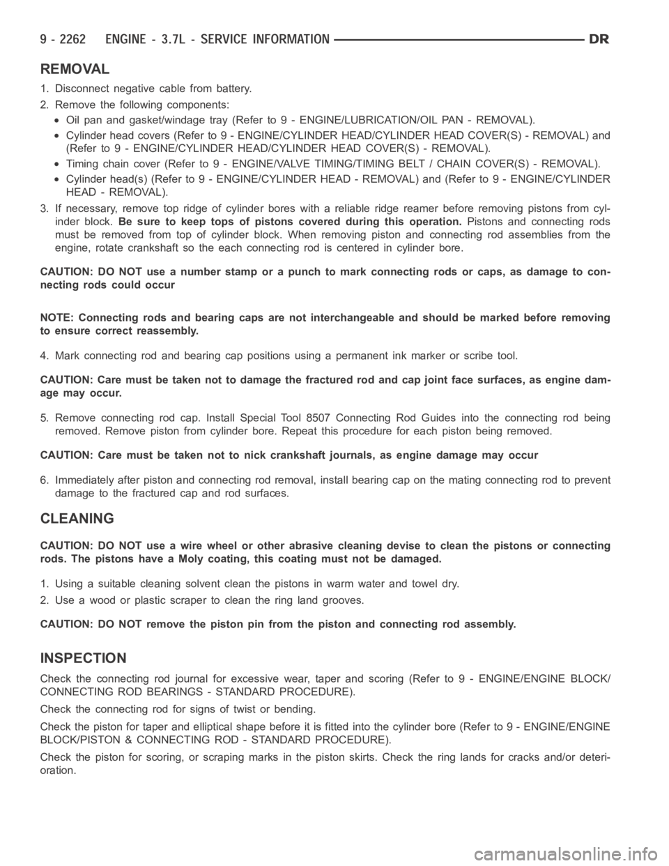
REMOVAL
1. Disconnect negative cable from battery.
2. Remove the following components:
Oil pan and gasket/windage tray (Refer to 9 - ENGINE/LUBRICATION/OIL PAN -REMOVAL).
Cylinder head covers (Refer to 9 - ENGINE/CYLINDER HEAD/CYLINDER HEAD COVER(S) - REMOVAL) and
(Refer to 9 - ENGINE/CYLINDER HEAD/CYLINDER HEAD COVER(S) - REMOVAL).
Timing chain cover (Refer to 9 - ENGINE/VALVE TIMING/TIMING BELT / CHAIN COVER(S) - REMOVAL).
Cylinder head(s) (Refer to 9 - ENGINE/CYLINDER HEAD - REMOVAL) and (Refer to 9 - ENGINE/CYLINDER
HEAD - REMOVAL).
3. If necessary, remove top ridge of cylinder bores with a reliable ridge reamer before removing pistons from cyl-
inder block.Be sure to keep tops of pistons covered during this operation.Pistons and connecting rods
must be removed from top of cylinder block. When removing piston and connecting rod assemblies from the
engine, rotate crankshaft so the each connecting rod is centered in cylinder bore.
CAUTION: DO NOT use a number stamp or a punch to mark connecting rods or caps,as damage to con-
necting rods could occur
NOTE: Connecting rods and bearing caps are not interchangeable and shouldbe marked before removing
to ensure correct reassembly.
4. Mark connecting rod and bearing cap positions using a permanent ink marker or scribe tool.
CAUTION: Care must be taken not to damage the fractured rod and cap joint face surfaces, as engine dam-
age may occur.
5. Remove connecting rod cap. Install Special Tool 8507 Connecting Rod Guides into the connecting rod being
removed. Remove piston from cylinder bore. Repeat this procedure for eachpiston being removed.
CAUTION: Care must be taken not to nick crankshaft journals, as engine damage may occur
6. Immediately after piston and connecting rod removal, install bearing cap on the mating connecting rod to prevent
damage to the fractured cap and rod surfaces.
CLEANING
CAUTION: DO NOT use a wire wheel or other abrasive cleaning devise to clean the pistons or connecting
rods. The pistons have a Moly coating, this coating must not be damaged.
1. Using a suitable cleaning solvent clean the pistons in warm water and towel dry.
2. Use a wood or plastic scraper to clean the ring land grooves.
CAUTION: DO NOT remove the piston pin from the piston and connecting rod assembly.
INSPECTION
Check the connecting rod journal for excessive wear, taper and scoring (Refer to 9 - ENGINE/ENGINE BLOCK/
CONNECTING ROD BEARINGS - STANDARD PROCEDURE).
Check the connecting rod for signs of twist or bending.
Check the piston for taper and elliptical shape before it is fitted into thecylinder bore (Refer to 9 - ENGINE/ENGINE
BLOCK/PISTON & CONNECTING ROD - STANDARD PROCEDURE).
Check the piston for scoring, or scraping marks in the piston skirts. Checkthe ring lands for cracks and/or deteri-
oration.
Page 1606 of 5267
VALVE TIMING
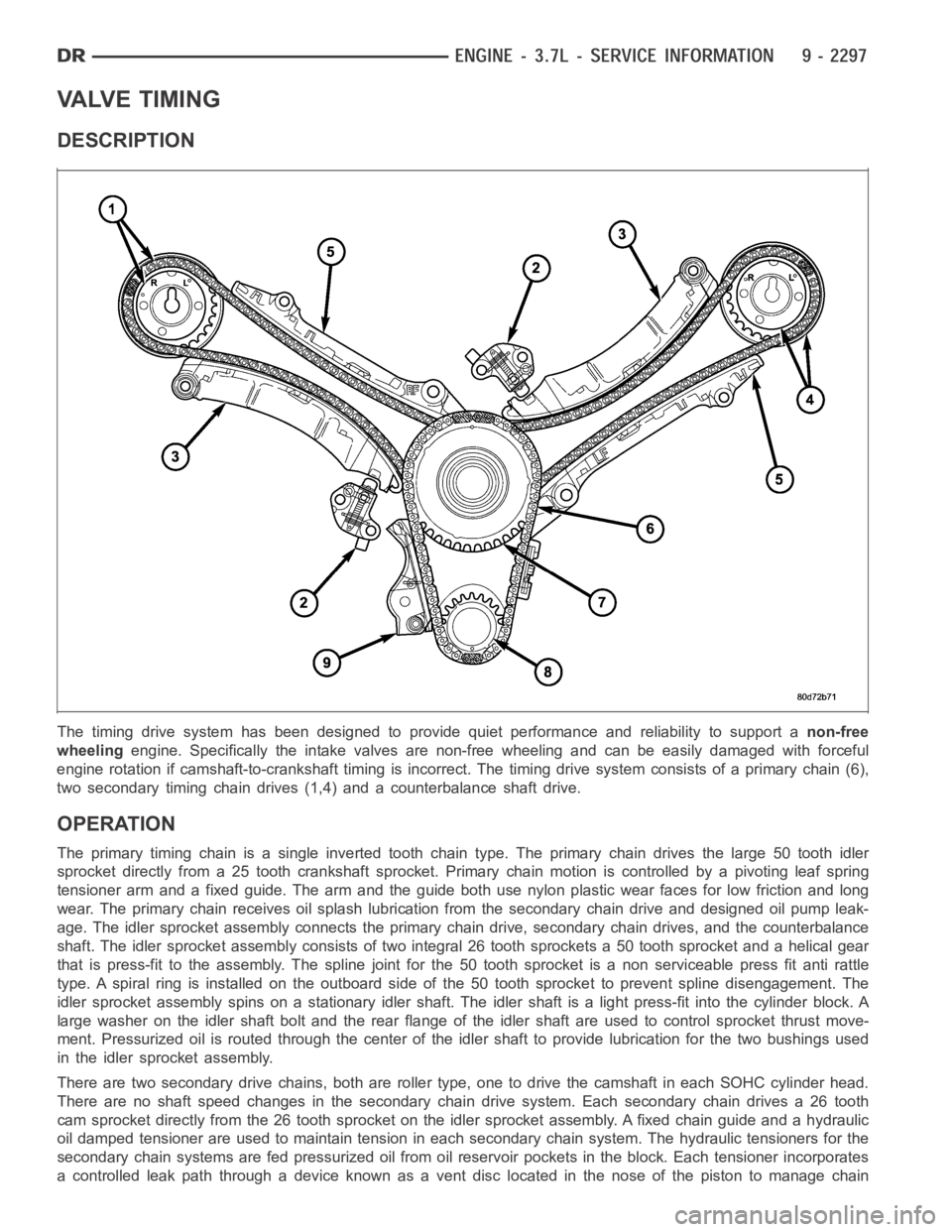
DESCRIPTION
The timing drive system has been designed to provide quiet performance andreliability to support anon-free
wheelingengine. Specifically the intake valves are non-free wheeling and can be easily damaged with forceful
engine rotation if camshaft-to-crankshaft timing is incorrect. The timing drive system consists of a primary chain (6),
two secondary timing chain drives (1,4) and a counterbalance shaft drive.
OPERATION
The primary timing chain is a single inverted tooth chain type. The primarychaindrivesthelarge50toothidler
sprocket directly from a 25 tooth crankshaft sprocket. Primary chain motion is controlled by a pivoting leaf spring
tensioner arm and a fixed guide. The arm and the guide both use nylon plasticwear faces for low friction and long
wear. The primary chain receives oil splash lubrication from the secondary chain drive and designed oil pump leak-
age. The idler sprocket assembly connects the primary chain drive, secondary chain drives, and the counterbalance
shaft. The idler sprocket assembly consists of two integral 26 tooth sprockets a 50 tooth sprocket and a helical gear
that is press-fit to the assembly. Thespline joint for the 50 tooth sprocket is a non serviceable press fit anti rattle
type. A spiral ring is installed on the outboard side of the 50 tooth sprocket to prevent spline disengagement. The
idler sprocket assembly spins on a stationary idler shaft. The idler shaftis a light press-fit into the cylinder block. A
large washer on the idler shaft bolt and the rear flange of the idler shaft are used to control sprocket thrust move-
ment. Pressurized oil is routed through the center of the idler shaft to provide lubrication for the two bushings used
in the idler sprocket assembly.
There are two secondary drive chains, both are roller type, one to drive thecamshaft in each SOHC cylinder head.
There are no shaft speed changes in the secondary chain drive system. Each secondary chain drives a 26 tooth
cam sprocket directly from the 26 tooth sprocket on the idler sprocket assembly. A fixed chain guide and a hydraulic
oil damped tensioner are used to maintain tension in each secondary chain system. The hydraulic tensioners for the
secondary chain systems are fed pressurized oil from oil reservoir pockets in the block. Each tensioner incorporates
a controlled leak path through a device known as a vent disc located in the nose of the piston to manage chain
Page 1627 of 5267
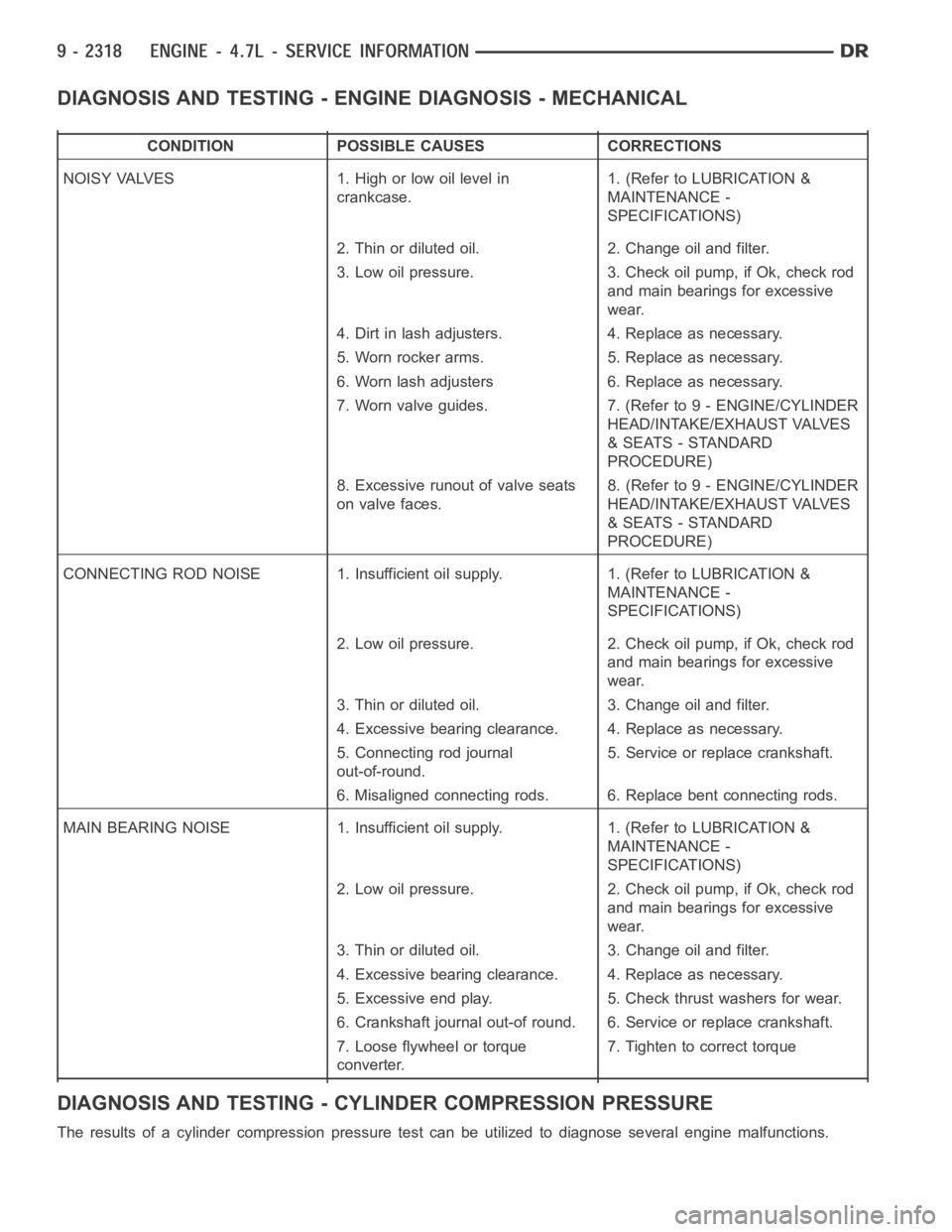
DIAGNOSIS AND TESTING - ENGINE DIAGNOSIS - MECHANICAL
CONDITION POSSIBLE CAUSES CORRECTIONS
NOISY VALVES 1. High or low oil level in
crankcase.1. (Refer to LUBRICATION &
MAINTENANCE -
SPECIFICATIONS)
2. Thin or diluted oil. 2. Change oil and filter.
3. Low oil pressure. 3. Check oil pump, if Ok, check rod
and main bearings for excessive
wear.
4. Dirt in lash adjusters. 4. Replace as necessary.
5. Worn rocker arms. 5. Replace as necessary.
6. Worn lash adjusters 6. Replace as necessary.
7. Worn valve guides. 7. (Refer to 9 - ENGINE/CYLINDER
HEAD/INTAKE/EXHAUST VALVES
& SEATS - STANDARD
PROCEDURE)
8. Excessive runout of valve seats
on valve faces.8. (Refer to 9 - ENGINE/CYLINDER
HEAD/INTAKE/EXHAUST VALVES
& SEATS - STANDARD
PROCEDURE)
CONNECTING ROD NOISE 1. Insufficient oil supply. 1. (Refer to LUBRICATION&
MAINTENANCE -
SPECIFICATIONS)
2. Low oil pressure. 2. Check oil pump, if Ok, check rod
and main bearings for excessive
wear.
3. Thin or diluted oil. 3. Change oil and filter.
4. Excessive bearing clearance. 4. Replace as necessary.
5. Connecting rod journal
out-of-round.5. Service or replace crankshaft.
6. Misaligned connecting rods. 6. Replace bent connecting rods.
MAIN BEARING NOISE 1. Insufficient oil supply. 1. (Refer to LUBRICATION &
MAINTENANCE -
SPECIFICATIONS)
2. Low oil pressure. 2. Check oil pump, if Ok, check rod
and main bearings for excessive
wear.
3. Thin or diluted oil. 3. Change oil and filter.
4. Excessive bearing clearance. 4. Replace as necessary.
5. Excessive end play. 5. Check thrust washers for wear.
6. Crankshaft journal out-of round. 6. Service or replace crankshaft.
7. Loose flywheel or torque
converter.7. Tighten to correct torque
DIAGNOSIS AND TESTING - CYLINDER COMPRESSION PRESSURE
The results of a cylinder compressionpressure test can be utilized to diagnose several engine malfunctions.
Page 1706 of 5267
REMOVAL
1. Disconnect negative cable from battery.
2. Remove the following components:
Oil pan and gasket/windage tray (Refer to 9 - ENGINE/LUBRICATION/OIL PAN -REMOVAL).
Cylinder head covers (Refer to 9 - ENGINE/CYLINDER HEAD/CYLINDER HEAD COVER(S) - REMOVAL) and
(Refer to 9 - ENGINE/CYLINDER HEAD/CYLINDER HEAD COVER(S) - REMOVAL).
Timing chain cover (Refer to 9 - ENGINE/VALVE TIMING/TIMING BELT / CHAIN COVER(S) - REMOVAL).
Cylinder head(s) (Refer to 9 - ENGINE/CYLINDER HEAD - REMOVAL) and (Refer to 9 - ENGINE/CYLINDER
HEAD - REMOVAL).
3. If necessary, remove top ridge of cylinder bores with a reliable ridge reamer before removing pistons from cyl-
inder block.Be sure to keep tops of pistons covered during this operation.Pistons and connecting rods
must be removed from top of cylinder block. When removing piston and connecting rod assemblies from the
engine, rotate crankshaft so the each connecting rod is centered in cylinder bore.
CAUTION: DO NOT use a number stamp or a punch to mark connecting rods or caps,as damage to con-
necting rods could occur
NOTE: Connecting rods and bearing caps are not interchangeable and shouldbe marked before removing
to ensure correct reassembly.
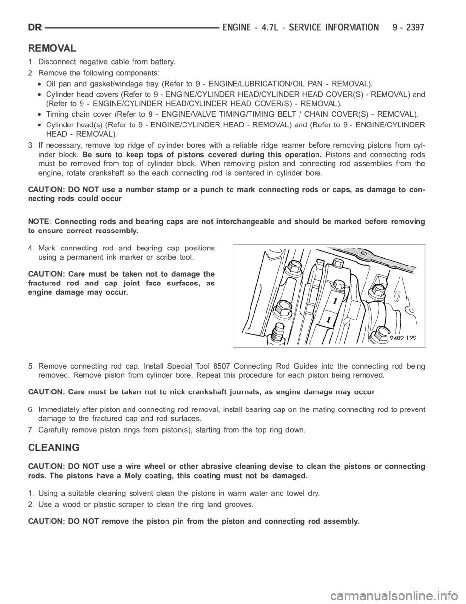
4. Mark connecting rod and bearing cap positions
using a permanent ink marker or scribe tool.
CAUTION: Care must be taken not to damage the
fractured rod and cap joint face surfaces, as
engine damage may occur.
5. Remove connecting rod cap. Install Special Tool 8507 Connecting Rod Guides into the connecting rod being
removed. Remove piston from cylinder bore. Repeat this procedure for eachpiston being removed.
CAUTION: Care must be taken not to nick crankshaft journals, as engine damage may occur
6. Immediately after piston and connecting rod removal, install bearing cap on the mating connecting rod to prevent
damage to the fractured cap and rod surfaces.
7. Carefully remove piston rings from piston(s), starting from the top ring down.
CLEANING
CAUTION: DO NOT use a wire wheel or other abrasive cleaning devise to clean the pistons or connecting
rods. The pistons have a Moly coating, this coating must not be damaged.
1. Using a suitable cleaning solvent clean the pistons in warm water and towel dry.
2. Use a wood or plastic scraper to clean the ring land grooves.
CAUTION: DO NOT remove the piston pin from the piston and connecting rod assembly.
Page 1739 of 5267
VALVE TIMING
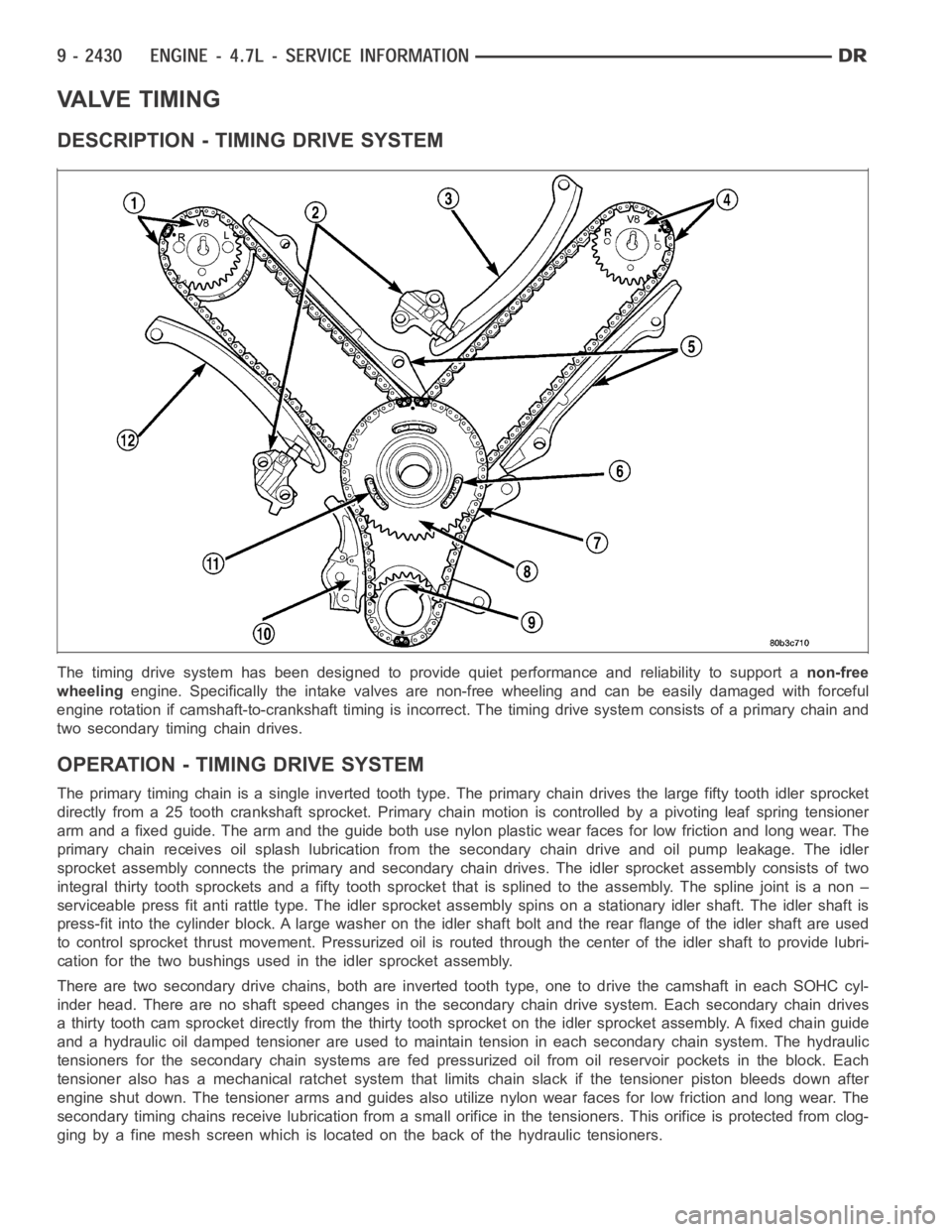
DESCRIPTION - TIMING DRIVE SYSTEM
The timing drive system has been designed to provide quiet performance andreliability to support anon-free
wheelingengine. Specifically the intake valves are non-free wheeling and can be easily damaged with forceful
engine rotation if camshaft-to-crankshaft timing is incorrect. The timing drive system consists of a primary chain and
two secondary timing chain drives.
OPERATION - TIMING DRIVE SYSTEM
The primary timing chain is a single inverted tooth type. The primary chaindrives the large fifty tooth idler sprocket
directly from a 25 tooth crankshaft sprocket. Primary chain motion is controlled by a pivoting leaf spring tensioner
arm and a fixed guide. The arm and the guide both use nylon plastic wear facesfor low friction and long wear. The
primary chain receives oil splash lubrication from the secondary chain drive and oil pump leakage. The idler
sprocket assembly connects the primary and secondary chain drives. The idler sprocket assembly consists of two
integral thirty tooth sprockets and afifty tooth sprocket that is splinedto the assembly. The spline joint is a non –
serviceable press fit anti rattle type. The idler sprocket assembly spinson a stationary idler shaft. The idler shaft is
press-fit into the cylinder block. A large washer on the idler shaft bolt and the rear flange of the idler shaft are used
to control sprocket thrust movement. Pressurized oil is routed through the center of the idler shaft to provide lubri-
cation for the two bushings used in the idler sprocket assembly.
There are two secondary drive chains, both are inverted tooth type, one to drive the camshaft in each SOHC cyl-
inder head. There are no shaft speed changes in the secondary chain drive system. Each secondary chain drives
a thirty tooth cam sprocket directly from the thirty tooth sprocket on the idler sprocket assembly. A fixed chain guide
and a hydraulic oil damped tensioner are used to maintain tension in each secondary chain system. The hydraulic
tensioners for the secondary chainsystems are fed pressurized oil from oil reservoir pockets in the block. Each
tensioner also has a mechanical ratchet system that limits chain slack if the tensioner piston bleeds down after
engine shut down. The tensioner arms and guides also utilize nylon wear faces for low friction and long wear. The
secondary timing chains receive lubrication from a small orifice in the tensioners. This orifice is protected from clog-
ging by a fine mesh screen which is located on the back of the hydraulic tensioners.