2006 DODGE RAM SRT-10 change wheel
[x] Cancel search: change wheelPage 3069 of 5267
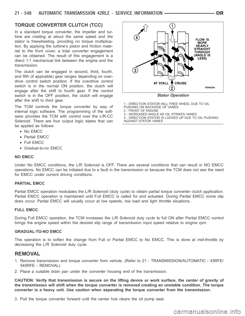
TORQUE CONVERTER CLUTCH (TCC)
In a standard torque converter, the impeller and tur-
bine are rotating at about the same speed and the
stator is freewheeling, providing no torque multiplica-
tion. By applying the turbine’s piston and friction mate-
rial to the front cover, a total converter engagement
can be obtained. The result of this engagement is a
direct 1:1 mechanical link between the engine and the
transmission.
The clutch can be engaged in second, third, fourth,
and fifth (if appicable) gear ranges depending on over-
drive control switch position. If the overdrive control
switch is in the normal ON position, the clutch will
engage after the shift to fourth gear. If the control
switch is in the OFF position, the clutch will engage
after the shift to third gear.
The TCM controls the torque converter by way of
internal logic software. The programming of the soft-
ware provides the TCM with control over the L/R-CC
Solenoid. There are four output logic states that can
be applied as follows:
No EMCC
Partial EMCC
Full EMCC
Gradual-to-no EMCC
NO EMCC
Under No EMCC conditions, the L/R Solenoid is OFF. There are several conditions that can result in NO EMCC
operations. No EMCC can be initiated due to a fault in the transmission or because the TCM does not see the need
for EMCC under current driving conditions.
PARTIAL EMCC
Partial EMCC operation modulates the L/R Solenoid (duty cycle) to obtain partial torque converter clutch application.
Partial EMCC operation is maintaineduntil Full EMCC is called for and actuated. During Partial EMCC some slip
does occur. Partial EMCC will usually occur at low speeds, low load and light throttle situations.
FULL EMCC
During Full EMCC operation, the TCM increases the L/R Solenoid duty cycle to full ON after Partial EMCC control
brings the engine speed within the desired slip range of transmission input speed relative to engine rpm.
GRADUAL-TO-NO EMCC
This operation is to soften the change from Full or Partial EMCC to No EMCC. This is done at mid-throttle by
decreasing the L/R Solenoid duty cycle.
REMOVAL
1. Remove transmission and torque converter from vehicle. (Refer to 21 - TRANSMISSION/AUTOMATIC - 45RFE/
545RFE - REMOVAL)
2. Place a suitable drain pan under the converter housing end of the transmission.
CAUTION: Verify that transmission is secure on the lifting device or work surface, the center of gravity of
the transmission will shift when the torque converter is removed creatingan unstable condition. The torque
converter is a heavy unit. Use caution when separating the torque converter from the transmission.
3. Pull the torque converter forward until the center hub clears the oil pumpseal.
Stator Operation
1 - DIRECTION STATOR WILL FREE WHEEL DUE TO OIL
PUSHING ON BACKSIDE OF VANES
2-FRONTOFENGINE
3 - INCREASED ANGLE AS OIL STRIKES VANES
4 - DIRECTION STATOR IS LOCKED UP DUE TO OIL PUSHING
AGAINST STATOR VANES
Page 3142 of 5267
When Monitored:
The transmission gear ratio is monitored continuously while the transmission is in gear.
Set Condition:
If there is an excessive change in output RPM in any gear. This DTC can take upto five minutes of problem
identification beforeilluminating the MIL.
Possible Causes
(T14) OUTPUT SPEED SENSOR SIGNAL CIRCUIT OPEN
(T13) SPEED SENSOR GROUND CIRCUIT OPEN
(T14) OUTPUT SPEED SENSOR SIGNAL CIRCUIT SHORT TO GROUND
(T13) SPEED SENSOR GROUND CIRCUIT SHORT TO GROUND
(T14) OUTPUT SPEED SENSOR SIGNAL CIRCUIT SHORT TO VOLTAGE
(T13) SPEED SENSOR GROUND CIRCUIT SHORT TO VOLTAGE
OUTPUT SPEED SENSOR
POWERTRAIN CONTROL MODULE
Always perform the 45RFE/545RFE Pre-Diagnostic Troubleshooting Procedure before proceeding. (Refer to
21 - TRANSMISSION/TRANSAXLE/AUTOMATIC - 45RFE/545RFE - STANDARD PROCEDURE)
Theory of Operation
The transmission system uses two speed sensors, one to measure input RPM and one to measure output RPM.
These inputs are essential for proper transmission operation. Therefore, the integrity of this data is verified through
the following checks:
1) When in gear, if the gear ratio does not compare to a known gear ratio, the corresponding in-gear trouble code
is set (codes P0731 through P0736).
2) An excessive change in input or output speeds indicating signal intermittent will result in codes P0715 and/or
P0720 being set.
3) If the common speed sensor ground circuit is lost, both sensor inputs will read the signal from the input speed
sensor at idle in neutral. Since the input speed sensor has 60 teeth and the output speed sensor has 30 teeth, this
results in a an apparent speed ratio of 1:2 and may cause the DTC P1794 to set.
Diagnostic Test
1.CHECK TO SEE IF DTC P0720 IS CURRENT
Turn the ignition off to the lock position.
CAUTION: Properly support the vehicle and raise all drive wheels off the ground.
Release the parking brake.
Start the engine in park.
Place the transmission gear selector in drive, release foot from brake.
WARNING: Be sure to keep hands and feet clear of rotation wheels.
With the scan tool, monitor the Output Speed Sensor RPM.
Is the Output Speed Sensor RPM below 100 RPM?
Ye s>>
Go To 2
No>>
Go To 9
Page 3152 of 5267
P0732-GEAR RATIO ERROR IN 2ND
For a complete wiring diagramRefer to Section 8W
When Monitored:
Continuously with the ignition on, engine running, with the transmissionin gear.
Set Condition:
If the ratio of the Input RPM to the Output RPM does not match the current gearratio. This DTC can take up
to five minutes of problem identification before illuminating the MIL
Possible Causes
RELATED DTC’S PRESENT
INPUT SPEED SENSOR OR WIRING
LOW FLUID LEVEL
CRACKED OR MIS-INSTALLED PRIMARY OIL FILTER OR SEAL
WORN SOLENOID SWITCH VALVE OR PLUGS
STUCK OR STICKING MAIN REGULATOR VALVE
BURNED UD OR 2C CLUTCH
CUT 2C OR UD PISTON SEAL
BROKEN 2C PISTON CASTING
BROKEN OR MISSING 2C BLEED ORIFICE
BROKEN OR MISSING UD BLEED ORIFICE
CUT 2C OR UD ACCUMULATOR PISTON SEAL
CRACKED 2C OR UD ACCUMULATOR PISTON
CUT OR MISSING #5 OR #7 CHECK BALL
TRANSMISSION SOLENOID/TRS ASSEMBLY
BROKEN WELD - REACTION CARRIER TO REVERSE SUN GEAR
MISSING TEETH ON INPUT CLUTCH HUB TONE WHEEL
Always perform the 45RFE/545RFE Pre-Diagnostic Troubleshooting Procedure before proceeding. (Refer to
21 - TRANSMISSION/TRANSAXLE/AUTOMATIC - 45RFE/545RFE - STANDARD PROCEDURE)
Theory of Operation
The transmission system uses two speed sensors, one to measure input RPM and one to measure output RPM.
These inputs are essential for proper transmission operation. Therefore, the integrity of this data is verified through
the following checks:
1) Once in a particular gear, if the gear ratio varies from the correct gear ratio, the corresponding in-gear trouble
code is set (DTCs P0731-36).
2) An excessive change in input or output speeds indicating signal intermittent may result in the DTCs P0715 and/or
P0720 being set.
3) If the common speed sensor ground circuit is lost, both sensor inputs will read the pulses from the input speed
sensor when at a stop in neutral. Since the input speed sensor reads 60 teethfrom the input clutch hub and the
output speed sensor reads 30 teeth from the park gear, the result is an apparent speed ratio of 1:2 and may cause
the DTC P1794 to set.
Page 3321 of 5267

P1736-GEAR RATIO ERROR IN 2ND PRIME
For a complete wiring diagramRefer to Section 8W.
When Monitored:
Continuously with the ignition on, engine running, with the transmissionin gear.
Set Condition:
If the ratio of the Input RPM to the Output RPM does not match the current gearratio. This DTC can take up
to five minutes of problem identification before illuminating the MIL
Possible Causes
RELATED DTC’S PRESENT
INPUT SPEED SENSOR OR WIRING
LOW FLUID LEVEL
CRACKED OR MIS-INSTALLED PRIMARY OIL FILTER OR SEAL
WORN SOLENOID SWITCH VALVE OR PLUGS
STUCK OR STICKING MAIN REGULATOR VALVE
BURNED UD OR 4C CLUTCH
CUT 4C OR UD PISTON SEAL
BROKEN 4C PISTON CASTING
BROKEN OR MISSING 4C BLEED ORIFICE
BROKEN OR MISSING UD BLEED ORIFICE
CUT 4C OR UD ACCUMULATOR PISTON SEAL
CRACKED 4C OR UD ACCUMULATOR PISTON
EXTRA CHECK BALL IN PASSAGE DOWNSTREAM OF #7 CHECK BALL POCKET
TRANSMISSION SOLENOID/TRS ASSEMBLY
BROKEN WELD - REACTION CARRIER TO REVERSE SUN GEAR
MISSING TEETH ON INPUT CLUTCH HUB TONE WHEEL
Always perform the 45RFE/545RFE Pre-Diagnostic Troubleshooting Procedure before proceeding. (Refer to
21 - TRANSMISSION/TRANSAXLE/AUTOMATIC - 45RFE/545RFE - STANDARD PROCEDURE)
Theory of Operation
The transmission system uses two speed sensors, one to measure input RPM and one to measure output RPM.
These inputs are essential for proper transmission operation. Therefore, the integrity of this data is verified through
the following checks:
1) When in gear, if the gear ratio does not compare to a known gear ratio, the corresponding in-gear trouble code
is set (DTCs P0731-36).
2) An excessive change in input or output speeds indicating signal intermittent which may result in the DTCs P0715
and/or P0720 to set.
3) If the common speed sensor ground circuit is lost, both sensor inputs will read the signal from the input speed
sensor at idle in neutral. Since the input speed sensor reads 60 teeth from the input clutch hub and the output
speed sensor reads 30 teeth from the park gear, the result is an apparent speed ratio of 1:2 and may cause the
DTC P1794 to set when at a stop.
Page 3487 of 5267
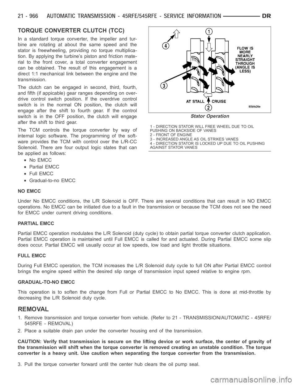
TORQUE CONVERTER CLUTCH (TCC)
In a standard torque converter, the impeller and tur-
bine are rotating at about the same speed and the
stator is freewheeling, providing no torque multiplica-
tion. By applying the turbine’s piston and friction mate-
rial to the front cover, a total converter engagement
can be obtained. The result of this engagement is a
direct 1:1 mechanical link between the engine and the
transmission.
The clutch can be engaged in second, third, fourth,
and fifth (if appicable) gear ranges depending on over-
drive control switch position. If the overdrive control
switch is in the normal ON position, the clutch will
engage after the shift to fourth gear. If the control
switch is in the OFF position, the clutch will engage
after the shift to third gear.
The TCM controls the torque converter by way of
internal logic software. The programming of the soft-
ware provides the TCM with control over the L/R-CC
Solenoid. There are four output logic states that can
be applied as follows:
No EMCC
Partial EMCC
Full EMCC
Gradual-to-no EMCC
NO EMCC
Under No EMCC conditions, the L/R Solenoid is OFF. There are several conditions that can result in NO EMCC
operations. No EMCC can be initiated due to a fault in the transmission or because the TCM does not see the need
for EMCC under current driving conditions.
PARTIAL EMCC
Partial EMCC operation modulates the L/R Solenoid (duty cycle) to obtain partial torque converter clutch application.
Partial EMCC operation is maintaineduntil Full EMCC is called for and actuated. During Partial EMCC some slip
does occur. Partial EMCC will usually occur at low speeds, low load and light throttle situations.
FULL EMCC
During Full EMCC operation, the TCM increases the L/R Solenoid duty cycle to full ON after Partial EMCC control
brings the engine speed within the desired slip range of transmission input speed relative to engine rpm.
GRADUAL-TO-NO EMCC
This operation is to soften the change from Full or Partial EMCC to No EMCC. This is done at mid-throttle by
decreasing the L/R Solenoid duty cycle.
REMOVAL
1. Remove transmission and torque converter from vehicle. (Refer to 21 - TRANSMISSION/AUTOMATIC - 45RFE/
545RFE - REMOVAL)
2. Place a suitable drain pan under the converter housing end of the transmission.
CAUTION: Verify that transmission is secure on the lifting device or work surface, the center of gravity of
the transmission will shift when the torque converter is removed creatingan unstable condition. The torque
converter is a heavy unit. Use caution when separating the torque converter from the transmission.
3. Pull the torque converter forward until the center hub clears the oil pumpseal.
Stator Operation
1 - DIRECTION STATOR WILL FREE WHEEL DUE TO OIL
PUSHING ON BACKSIDE OF VANES
2-FRONTOFENGINE
3 - INCREASED ANGLE AS OIL STRIKES VANES
4 - DIRECTION STATOR IS LOCKED UP DUE TO OIL PUSHING
AGAINST STATOR VANES
Page 3801 of 5267
5. Line pressure should be 54-60 psi (372-414 kPa) with throttle lever forward and gradually increase to 90-96 psi
(621-662 kPa) as lever is moved rearward.
Test Three - Transmission In D Range Third Gear
This test checks pressure regulation and condition of the clutch circuits. Both test gauges are required for this test.
1. Turn OD switch off.
2. Leave vehicle on hoist and leave Oil Pressure Gauge C-3292 in place at accumulator port.
3. Move Oil Pressure Gauge C-3293-SP over to front servo port for this test.
4. Have helper start and run engine at 1600 rpm for this test.
5. Move transmission shift lever two detents rearward from full forward position. This is D range.
6. Read pressures on both gauges as transmission throttle lever is gradually moved from full forward to full rear-
ward position:
Line pressure at accumulator in D range third gear, should be 54-60 psi (372-414 kPa) with throttle lever for-
ward and increase as lever is moved rearward.
Front servo pressure in D range third gear, should be within 3 psi (21 kPa) ofline pressure up to kickdown
point.
Test Four - Transmission In Reverse
This test checks pump output, pressure regulation and the front clutch andrear servo circuits. Use 300 psi Oil
Pressure Gauge C-3293-SP for this test.
1. Leave vehicle on hoist and leave Oil Pressure Gauge C-3292 in place at accumulator port.
2. Move 300 psi Oil Pressure Gauge C-3293-SP back to rear servo port.
3. Have helper start and run engine at 1600 rpm for test.
4. Move transmission shift lever four detents rearward from full forward position. This is Reverse range.
5. Move transmission throttle lever fully forward then fully rearward andnote reading at Gauge C-3293-SP.
6. Pressure should be 145 - 175 psi (1000-1207 kPa) with throttle lever forward and increase to 230 - 280 psi
(1586-1931 kPa) as lever is gradually moved rearward.
Test Five - Governor Pressure
This test checks governor operation by measuring governor pressure response to changes in vehicle speed. It is
usually not necessary to check governor operation unless shift speeds areincorrect or if the transmission will not
downshift. The test should be performed on the road or on a hoist that will allow the rear wheels to rotate freely.
1. Move 100 psi Oil Pressure Gauge C-3292 to governor pressure port.
2. Move transmission shift lever two detents rearward from full forward position. This is D range.
3. Have helper start and run engine at curb idle speed. Then firmly apply service brakes so wheels will not rotate.
4. Note governor pressure:
Governor pressure should be no more than 20.6 kPa (3 psi) at curb idle speed and wheels not rotating.
If pressure exceeds 20.6 kPa (3 psi), a fault exists in governor pressure control system.
5. Release brakes, slowly increase engine speed, and observe speedometerand pressure test gauge (do not
exceed 30 mph on speedometer). Governor pressure should increase in proportion to vehicle speed. Or approx-
imately 6.89 kPa (1 psi) for every 1 mph.
6. Governor pressure rise should be smooth and drop back to no more than 20.6kPa (3 psi), after engine returns
to curb idle and brakes are applied to prevent wheels from rotating.
7. Compare results of pressure test with analysis chart.
Test Six - Transmission In Overdrive Fourth Gear
This test checks line pressure at the overdrive clutch in fourth gear range. Use 300 psi Oil Pressure Gauge
C-3293-SP for this test. The test should be performed on the road or on a chassis dyno.
1. Remove tachometer; it is not needed for this test.
2. Move 300 psi Oil Pressure Gauge to overdrive clutch pressure test port. Then remove other gauge and reinstall
test port plug.
Page 3870 of 5267
WIDE OPEN THROTTLE OPERATION
In wide-open throttle (WOT) mode, adaptive memory in the PCM assures that up-shifts occur at the preprogrammed
optimum speed. WOT operation is determined from the throttle position sensor, which is also a part of the emission
control system. The initial setting for the WOT upshift is below the optimum engine speed. As WOT shifts are
repeated, the PCM learns the time required to complete the shifts by comparing the engine speed when the shifts
occur to the optimum speed. After each shift, the PCM adjusts the shift point until the optimum speed is reached.
The PCM also considers vehicle loading, grade and engine performance changes due to high altitude in determining
when to make WOT shifts. It does this by measuring vehicle and engine acceleration and then factoring in the shift
time.
TRANSFER CASE LOW RANGE OPERATION
On four-wheel drive vehicles operating in low range, the engine can accelerate to its peak more rapidly than in
Normal range, resulting in delayed shifts and undesirable engine
flare.The low range governor pressure curve is
also higher than normal to initiate upshifts sooner. The PCM compares electronic vehicle speed signal used by the
speedometer to the transmission output shaft speed signal to determine when the transfer case is in low range.
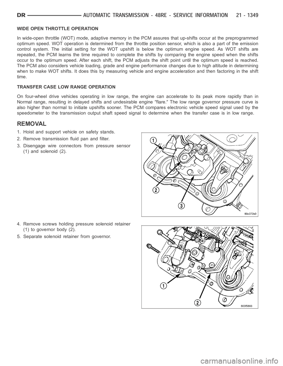
REMOVAL
1. Hoist and support vehicle on safety stands.
2. Remove transmission fluid pan and filter.
3. Disengage wire connectors from pressure sensor
(1) and solenoid (2).
4. Remove screws holding pressure solenoid retainer
(1) to governor body (2).
5. Separate solenoid retainer from governor.
Page 4178 of 5267
TRANSFER CASE - NV243 - SERVICE INFORMATION
DESCRIPTION
The NV243 is an electronically controlled part-time transfer case with a low range gear reduction system. The
NV243 has three operating ranges plus a NEUTRAL position. The low range system provides a gear reduction ratio
for increased low speed torque capability.
The geartrain is mounted in two aluminum case halves attached with bolts. The mainshaft front and rear bearings
are mounted in aluminum retainer housings bolted to the case halves.
OPERATING RANGES
Transfer case operating ranges are:
2WD (2-wheel drive).
4HI (4-wheel drive).
4LO (4-wheel drive low range).
NEUTRAL.
The 2WD range is for use on any road surface at any time.
The 4HI and 4LO ranges are for off road use only. They are not for use on hard surface roads. The only exception
being when the road surface is wet or slippery or covered by ice and snow.
The low range reduction gear system is operative in 4LO range only. This range is for extra pulling power in off road
situations. Low range reduction ratio is 2.72:1.
SHIFT MECHANISM
Operating ranges are selected with a dash mounted shift selector switch. The shift selector switch provides a input
to the Transfer Case Control Module (TCCM) to indicate the driver’s desireto change operating ranges. The TCCM
uses this input, along with input from the transfer case mounted mode sensor and information from the vehicle’s
bus, to determine if a shift is permitted. If the TCCM decides the shift is permitted, the TCCM controls the shift
motor, mounted to the exterior of the transfer case, to perform the shift.
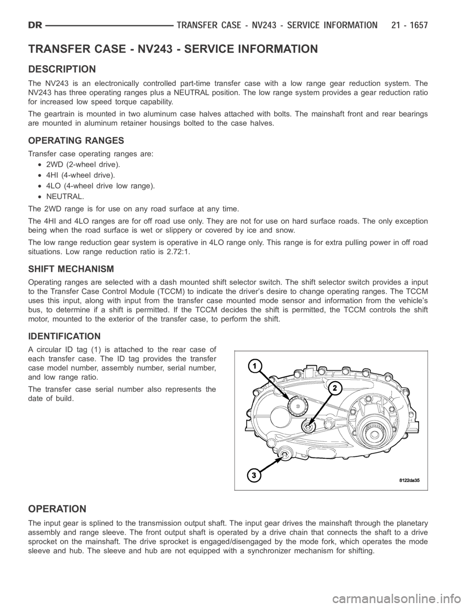
IDENTIFICATION
A circular ID tag (1) is attached to the rear case of
each transfer case. The ID tag provides the transfer
case model number, assembly number, serial number,
and low range ratio.
The transfer case serial number also represents the
date of build.
OPERATION
The input gear is splined to the transmission output shaft. The input gear drives the mainshaft through the planetary
assembly and range sleeve. The front output shaft is operated by a drive chain that connects the shaft to a drive
sprocket on the mainshaft. The drive sprocket is engaged/disengaged by themodefork,whichoperatesthemode
sleeve and hub. The sleeve and hub are not equipped with a synchronizer mechanism for shifting.