2006 DODGE RAM SRT-10 change wheel
[x] Cancel search: change wheelPage 1760 of 5267
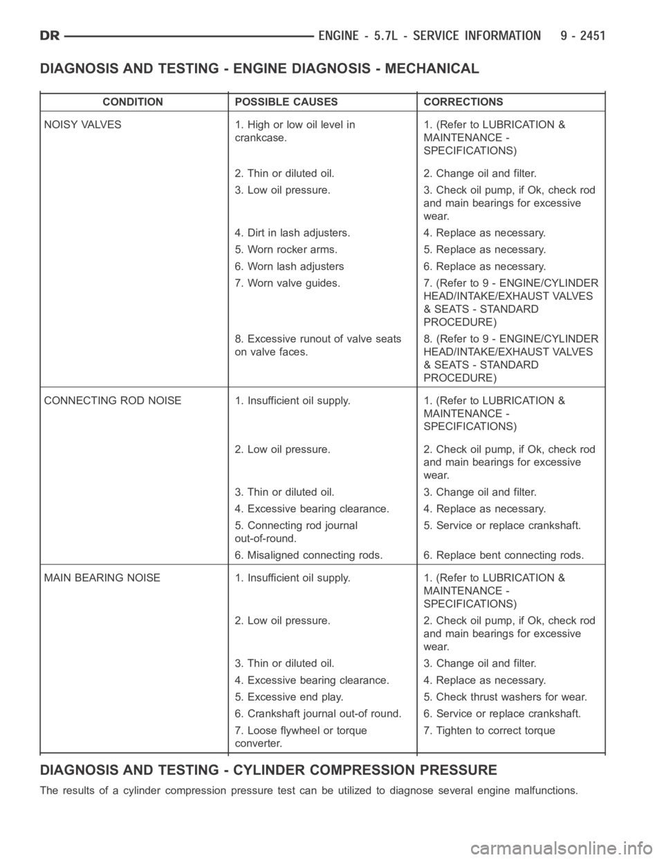
DIAGNOSIS AND TESTING - ENGINE DIAGNOSIS - MECHANICAL
CONDITION POSSIBLE CAUSES CORRECTIONS
NOISY VALVES 1. High or low oil level in
crankcase.1. (Refer to LUBRICATION &
MAINTENANCE -
SPECIFICATIONS)
2. Thin or diluted oil. 2. Change oil and filter.
3. Low oil pressure. 3. Check oil pump, if Ok, check rod
and main bearings for excessive
wear.
4. Dirt in lash adjusters. 4. Replace as necessary.
5. Worn rocker arms. 5. Replace as necessary.
6. Worn lash adjusters 6. Replace as necessary.
7. Worn valve guides. 7. (Refer to 9 - ENGINE/CYLINDER
HEAD/INTAKE/EXHAUST VALVES
& SEATS - STANDARD
PROCEDURE)
8. Excessive runout of valve seats
on valve faces.8. (Refer to 9 - ENGINE/CYLINDER
HEAD/INTAKE/EXHAUST VALVES
& SEATS - STANDARD
PROCEDURE)
CONNECTING ROD NOISE 1. Insufficient oil supply. 1. (Refer to LUBRICATION&
MAINTENANCE -
SPECIFICATIONS)
2. Low oil pressure. 2. Check oil pump, if Ok, check rod
and main bearings for excessive
wear.
3. Thin or diluted oil. 3. Change oil and filter.
4. Excessive bearing clearance. 4. Replace as necessary.
5. Connecting rod journal
out-of-round.5. Service or replace crankshaft.
6. Misaligned connecting rods. 6. Replace bent connecting rods.
MAIN BEARING NOISE 1. Insufficient oil supply. 1. (Refer to LUBRICATION &
MAINTENANCE -
SPECIFICATIONS)
2. Low oil pressure. 2. Check oil pump, if Ok, check rod
and main bearings for excessive
wear.
3. Thin or diluted oil. 3. Change oil and filter.
4. Excessive bearing clearance. 4. Replace as necessary.
5. Excessive end play. 5. Check thrust washers for wear.
6. Crankshaft journal out-of round. 6. Service or replace crankshaft.
7. Loose flywheel or torque
converter.7. Tighten to correct torque
DIAGNOSIS AND TESTING - CYLINDER COMPRESSION PRESSURE
The results of a cylinder compressionpressure test can be utilized to diagnose several engine malfunctions.
Page 1764 of 5267
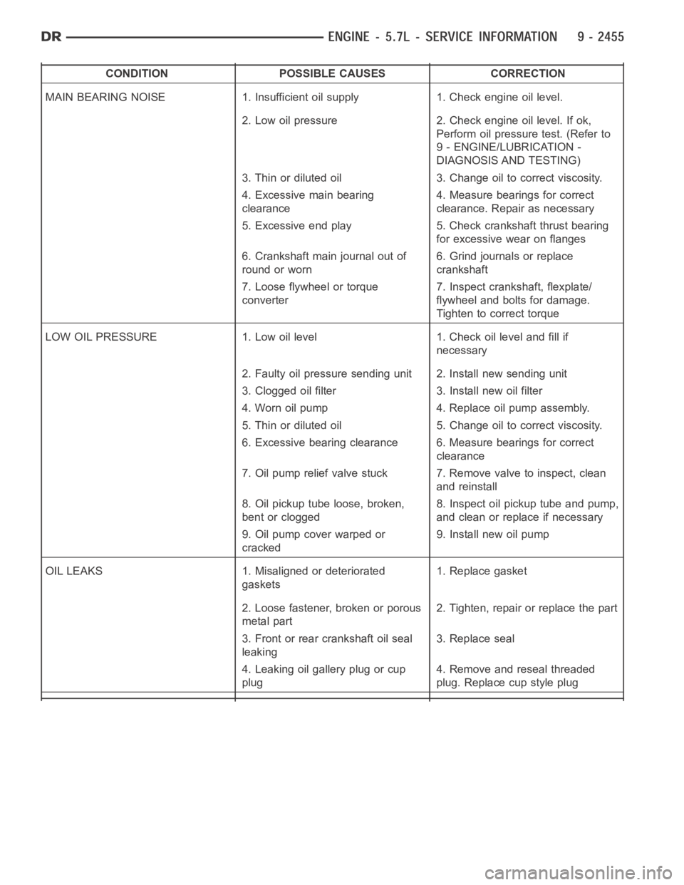
CONDITION POSSIBLE CAUSES CORRECTION
MAIN BEARING NOISE 1. Insufficient oil supply 1. Check engine oil level.
2. Low oil pressure 2. Check engine oil level. If ok,
Perform oil pressure test. (Refer to
9 - ENGINE/LUBRICATION -
DIAGNOSIS AND TESTING)
3. Thin or diluted oil 3. Change oil to correct viscosity.
4. Excessive main bearing
clearance4. Measure bearings for correct
clearance. Repair as necessary
5. Excessive end play 5. Check crankshaft thrust bearing
for excessive wear on flanges
6. Crankshaft main journal out of
round or worn6. Grind journals or replace
crankshaft
7. Loose flywheel or torque
converter7. Inspect crankshaft, flexplate/
flywheel and bolts for damage.
Tighten to correct torque
LOW OIL PRESSURE 1. Low oil level 1. Check oil level and fill if
necessary
2. Faulty oil pressure sending unit 2. Install new sending unit
3. Clogged oil filter 3. Install new oil filter
4. Worn oil pump 4. Replace oil pump assembly.
5. Thin or diluted oil 5. Change oil to correct viscosity.
6. Excessive bearing clearance 6. Measure bearings for correct
clearance
7. Oil pump relief valve stuck 7. Remove valve to inspect, clean
and reinstall
8. Oil pickup tube loose, broken,
bent or clogged8. Inspect oil pickup tube and pump,
and clean or replace if necessary
9. Oil pump cover warped or
cracked9. Install new oil pump
OIL LEAKS 1. Misaligned or deteriorated
gaskets1. Replace gasket
2. Loose fastener, broken or porous
metal part2. Tighten, repair or replace the part
3. Front or rear crankshaft oil seal
leaking3. Replace seal
4. Leaking oil gallery plug or cup
plug4. Remove and reseal threaded
plug. Replace cup style plug
Page 1909 of 5267
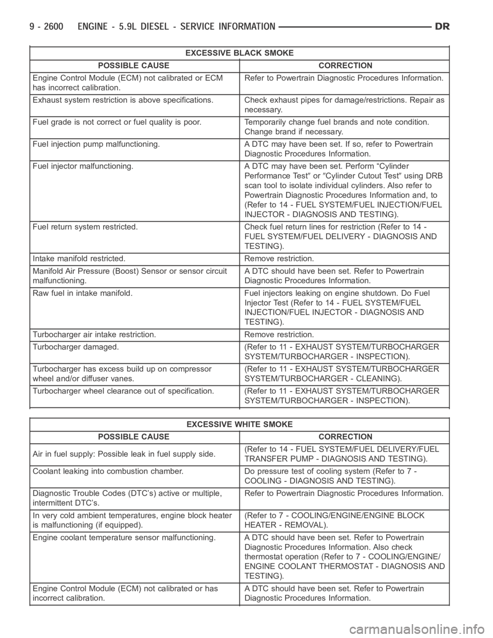
EXCESSIVE BLACK SMOKE
POSSIBLE CAUSE CORRECTION
Engine Control Module (ECM) not calibrated or ECM
has incorrect calibration.Refer to Powertrain Diagnostic Procedures Information.
Exhaust system restriction is above specifications. Check exhaust pipesfor damage/restrictions. Repair as
necessary.
Fuel grade is not correct or fuel quality is poor. Temporarily change fuel brands and note condition.
Change brand if necessary.
Fuel injection pump malfunctioning. A DTC may have been set. If so, refer toPowertrain
Diagnostic Procedures Information.
Fuel injector malfunctioning. A DTC may have been set. Perform “Cylinder
Performance Test
orCylinder Cutout Testusing DRB
scan tool to isolate individual cylinders. Also refer to
Powertrain Diagnostic Procedures Information and, to
(Refer to 14 - FUEL SYSTEM/FUEL INJECTION/FUEL
INJECTOR - DIAGNOSIS AND TESTING).
Fuel return system restricted. Check fuel return lines for restriction (Refer to 14 -
FUEL SYSTEM/FUEL DELIVERY - DIAGNOSIS AND
TESTING).
Intake manifold restricted. Remove restriction.
Manifold Air Pressure (Boost) Sensor or sensor circuit
malfunctioning.A DTC should have been set. Refer to Powertrain
Diagnostic Procedures Information.
Raw fuel in intake manifold. Fuel injectors leaking on engine shutdown. DoFuel
Injector Test (Refer to 14 - FUEL SYSTEM/FUEL
INJECTION/FUEL INJECTOR - DIAGNOSIS AND
TESTING).
Turbocharger air intake restriction. Remove restriction.
Turbocharger damaged. (Refer to 11 - EXHAUST SYSTEM/TURBOCHARGER
SYSTEM/TURBOCHARGER - INSPECTION).
Turbocharger has excess build up on compressor
wheel and/or diffuser vanes.(Refer to 11 - EXHAUST SYSTEM/TURBOCHARGER
SYSTEM/TURBOCHARGER - CLEANING).
Turbocharger wheel clearance out of specification. (Refer to 11 - EXHAUSTSYSTEM/TURBOCHARGER
SYSTEM/TURBOCHARGER - INSPECTION).
EXCESSIVE WHITE SMOKE
POSSIBLE CAUSE CORRECTION
Air in fuel supply: Possible leak in fuel supply side.(Refer to 14 - FUEL SYSTEM/FUEL DELIVERY/FUEL
TRANSFER PUMP - DIAGNOSIS AND TESTING).
Coolant leaking into combustion chamber. Do pressure test of cooling system (Refer to 7 -
COOLING - DIAGNOSIS AND TESTING).
Diagnostic Trouble Codes (DTC’s) active or multiple,
intermittent DTC’s.Refer to Powertrain Diagnostic Procedures Information.
In very cold ambient temperatures, engine block heater
is malfunctioning (if equipped).(Refer to 7 - COOLING/ENGINE/ENGINE BLOCK
HEATER - REMOVAL).
Engine coolant temperature sensor malfunctioning. A DTC should have beenset. Refer to Powertrain
Diagnostic Procedures Information. Also check
thermostat operation (Refer to 7 - COOLING/ENGINE/
ENGINE COOLANT THERMOSTAT - DIAGNOSIS AND
TESTING).
Engine Control Module (ECM) not calibrated or has
incorrect calibration.A DTC should have been set. Refer to Powertrain
Diagnostic Procedures Information.
Page 2026 of 5267
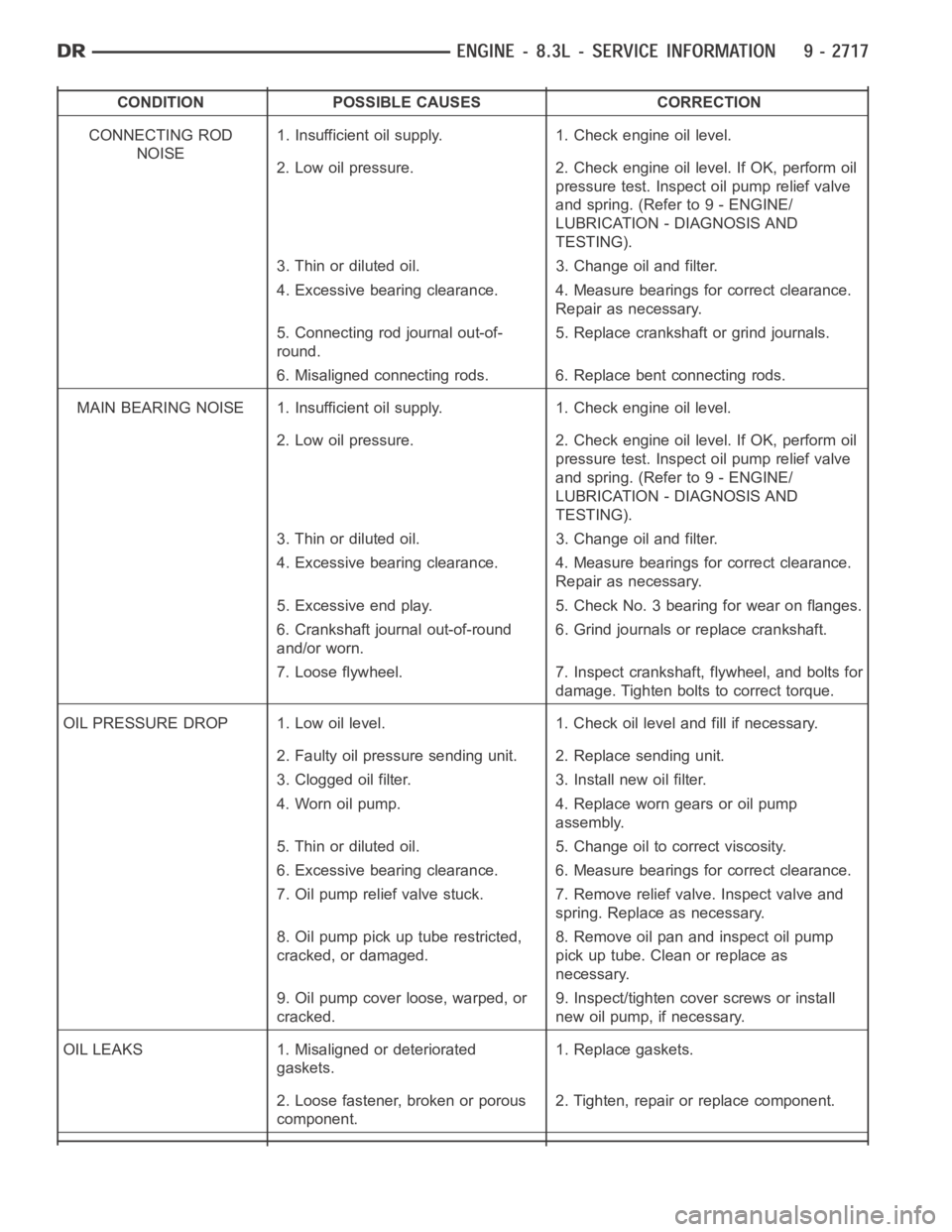
CONDITION POSSIBLE CAUSES CORRECTION
CONNECTING ROD
NOISE1. Insufficient oil supply. 1. Check engine oil level.
2. Low oil pressure. 2. Check engine oil level. If OK, perform oil
pressure test. Inspect oil pump relief valve
and spring. (Refer to 9 - ENGINE/
LUBRICATION - DIAGNOSIS AND
TESTING).
3. Thin or diluted oil. 3. Change oil and filter.
4. Excessive bearing clearance. 4. Measure bearings for correct clearance.
Repair as necessary.
5. Connecting rod journal out-of-
round.5. Replace crankshaft or grind journals.
6. Misaligned connecting rods. 6. Replace bent connecting rods.
MAIN BEARING NOISE 1. Insufficient oil supply. 1. Check engine oil level.
2. Low oil pressure. 2. Check engine oil level. If OK, perform oil
pressure test. Inspect oil pump relief valve
and spring. (Refer to 9 - ENGINE/
LUBRICATION - DIAGNOSIS AND
TESTING).
3. Thin or diluted oil. 3. Change oil and filter.
4. Excessive bearing clearance. 4. Measure bearings for correct clearance.
Repair as necessary.
5. Excessive end play. 5. Check No. 3 bearing for wear on flanges.
6. Crankshaft journal out-of-round
and/or worn.6. Grind journals or replace crankshaft.
7. Loose flywheel. 7. Inspect crankshaft, flywheel, and bolts for
damage. Tighten bolts to correct torque.
OIL PRESSURE DROP 1. Low oil level. 1. Check oil level and fill if necessary.
2. Faulty oil pressure sending unit. 2. Replace sending unit.
3. Clogged oil filter. 3. Install new oil filter.
4. Worn oil pump. 4. Replace worn gears or oil pump
assembly.
5. Thin or diluted oil. 5. Change oil to correct viscosity.
6. Excessive bearing clearance. 6. Measure bearings for correct clearance.
7. Oil pump relief valve stuck. 7. Remove relief valve. Inspect valve and
spring. Replace as necessary.
8. Oil pump pick up tube restricted,
cracked, or damaged.8. Remove oil pan and inspect oil pump
pick up tube. Clean or replace as
necessary.
9. Oil pump cover loose, warped, or
cracked.9. Inspect/tighten cover screws or install
new oil pump, if necessary.
OIL LEAKS 1. Misaligned or deteriorated
gaskets.1. Replace gaskets.
2. Loose fastener, broken or porous
component.2. Tighten, repair or replace component.
Page 2380 of 5267
SENSOR-CAMSHAFT POSITION
DESCRIPTION
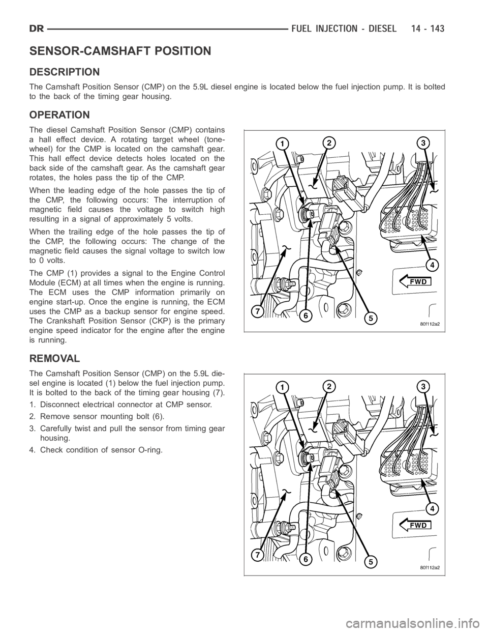
The Camshaft Position Sensor (CMP) on the 5.9L diesel engine is located below the fuel injection pump. It is bolted
to the back of the timing gear housing.
OPERATION
The diesel Camshaft Position Sensor (CMP) contains
a hall effect device. A rotating target wheel (tone-
wheel) for the CMP is located on the camshaft gear.
This hall effect device detects holes located on the
back side of the camshaft gear. As the camshaft gear
rotates, the holes pass the tip of the CMP.
When the leading edge of the hole passes the tip of
the CMP, the following occurs: The interruption of
magnetic field causes the voltage to switch high
resulting in a signal of approximately 5 volts.
When the trailing edge of the hole passes the tip of
the CMP, the following occurs: The change of the
magnetic field causes the signal voltage to switch low
to 0 volts.
The CMP (1) provides a signal to the Engine Control
Module (ECM) at all times when the engine is running.
TheECMusestheCMPinformationprimarilyon
engine start-up. Once the engine is running, the ECM
uses the CMP as a backup sensor for engine speed.
The Crankshaft Position Sensor (CKP) is the primary
engine speed indicator for the engine after the engine
is running.
REMOVAL
The Camshaft Position Sensor (CMP) on the 5.9L die-
sel engine is located (1) below the fuel injection pump.
It is bolted to the back of the timing gear housing (7).
1. Disconnect electrical connector at CMP sensor.
2. Remove sensor mounting bolt (6).
3. Carefully twist and pull the sensor from timing gear
housing.
4. Check condition of sensor O-ring.
Page 2382 of 5267
SENSOR-CRANKSHAFT POSITION
DESCRIPTION
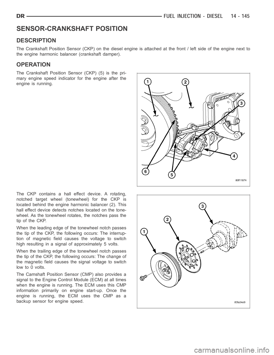
The Crankshaft Position Sensor (CKP) on the diesel engine is attached at thefront/leftsideoftheenginenextto
the engine harmonic balancer (crankshaft damper).
OPERATION
The Crankshaft Position Sensor (CKP) (5) is the pri-
mary engine speed indicator for the engine after the
engine is running.
The CKP contains a hall effect device. A rotating,
notched target wheel (tonewheel) for the CKP is
located behind the engine harmonic balancer (2). This
hall effect device detects notches located on the tone-
wheel. As the tonewheel rotates, the notches pass the
tip of the CKP.
When the leading edge of the tonewheel notch passes
the tip of the CKP, the following occurs: The interrup-
tion of magnetic field causes the voltage to switch
high resulting in a signal of approximately 5 volts.
When the trailing edge of the tonewheel notch passes
the tip of the CKP, the following occurs: The change of
the magnetic field causes the signal voltage to switch
lowto0volts.
The Camshaft Position Sensor (CMP) also provides a
signal to the Engine Control Module (ECM) at all times
when the engine is running. The ECM uses this CMP
information primarily on engine start-up. Once the
engine is running, the ECM uses the CMP as a
backup sensor for engine speed.
Page 2407 of 5267
STEERING
DESCRIPTION
CAUTION: MOPARATF+4 is to be used in the power steering system. No other power steering or auto-
matic transmission fluid is to be used in the system. Damage may result to the power steering pump and
system if any other fluid is used, and do not overfill.
Power steering systems consist of:
Steering column
Rack and pinion steering gear
Belt driven hydraulic steering pump
Pump pressure and return hoses
Oil Cooler
OPERATION
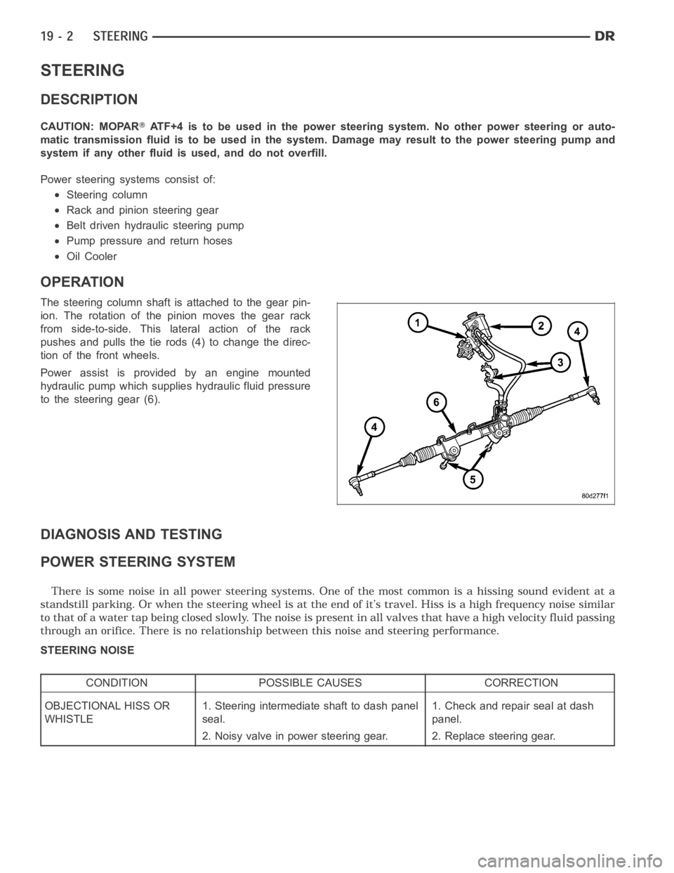
The steering column shaft isattached to the gear pin-
ion. The rotation of the pinion moves the gear rack
from side-to-side. This lateral action of the rack
pushes and pulls the tie rods (4) to change the direc-
tion of the front wheels.
Power assist is provided by an engine mounted
hydraulic pump which supplies hydraulic fluid pressure
to the steering gear (6).
DIAGNOSIS AND TESTING
POWER STEERING SYSTEM
STEERING NOISE
CONDITION POSSIBLE CAUSES CORRECTION
OBJECTIONAL HISS OR
WHISTLE1. Steering intermediate shaft to dash panel
seal.1. Check and repair seal at dash
panel.
2. Noisy valve in power steering gear. 2. Replace steering gear.
Page 2765 of 5267
When Monitored:
The transmission gear ratio is monitored continuously while the transmission is in gear.
Set Condition:
If there is an excessive change in the Output RPM in any gear.
Possible Causes
(T14) OUTPUT SPEED SENSOR SIGNAL CIRCUIT OPEN
(T13) SPEED SENSOR GROUND CIRCUIT OPEN
(T14) OUTPUT SPEED SENSOR SIGNAL CIRCUIT SHORT TO GROUND
(T14) OUTPUT SPEED SENSOR SIGNAL CIRCUIT SHORT TO VOLTAGE
(T13) SPEED SENSOR GROUND CIRCUIT SHORT TO VOLTAGE
OUTPUT SPEED SENSOR
POWERTRAIN CONTROL MODULE
Always perform the Pre-Diagnostic Troubleshooting procedure before proceeding. (Refer to 21 - TRANSMIS-
SION/TRANSAXLE/AUTOMATIC - 42RLE - STANDARD PROCEDURE)
Theory of Operation
The transmission system uses two speed sensors, one to measure input RPM and one to measure output RPM.
These inputs are essential for proper transmission operation. Therefore, the integrity of this data is verified through
system checks.
Diagnostic Test
1.CHECK IF THE DTC IS CURRENT
Start the engine in park.
Raise the drive wheels off of the ground.
WARNING: Properly support the vehicle.
Firmly apply the brakes and place the transmission selector in drive.
WARNING: Be sure to keep hands and feet clear of rotating wheels.
Release the brakes and allow the drive wheels to spin freely.
NOTE: The drive wheels must be turning at this point.
With the scan tool, read the Output RPM
Is the Output RPM below 100?
Ye s>>
Go To 2
No>>
Go To 8
2.CHECK THE PCM AND WIRING USING THE TRANSMISSION SIMULATOR
Turn the ignition off to the lock position.
Remove the Ignition Switch Feed fuse from the TIPM.
CAUTION: Removal of the Ignition Switch Feed fuse from the TIPM will prevent the vehicle from being
startedingear.
WARNING: The Ignition Switch Feed fuse must be removed from the TIPM. Failure to do so can result in
personal injury or death.
Install the Transmission Simulator,Miller tool #8333 and the ElectronicTransmission Adapter kit.
Ignition on, engine not running.
With the Transmission Simulator, set the
Input/Output Speedswitch toONand the rotary switch to the3000/
1250
position.