2006 DODGE RAM SRT-10 display
[x] Cancel search: displayPage 969 of 5267
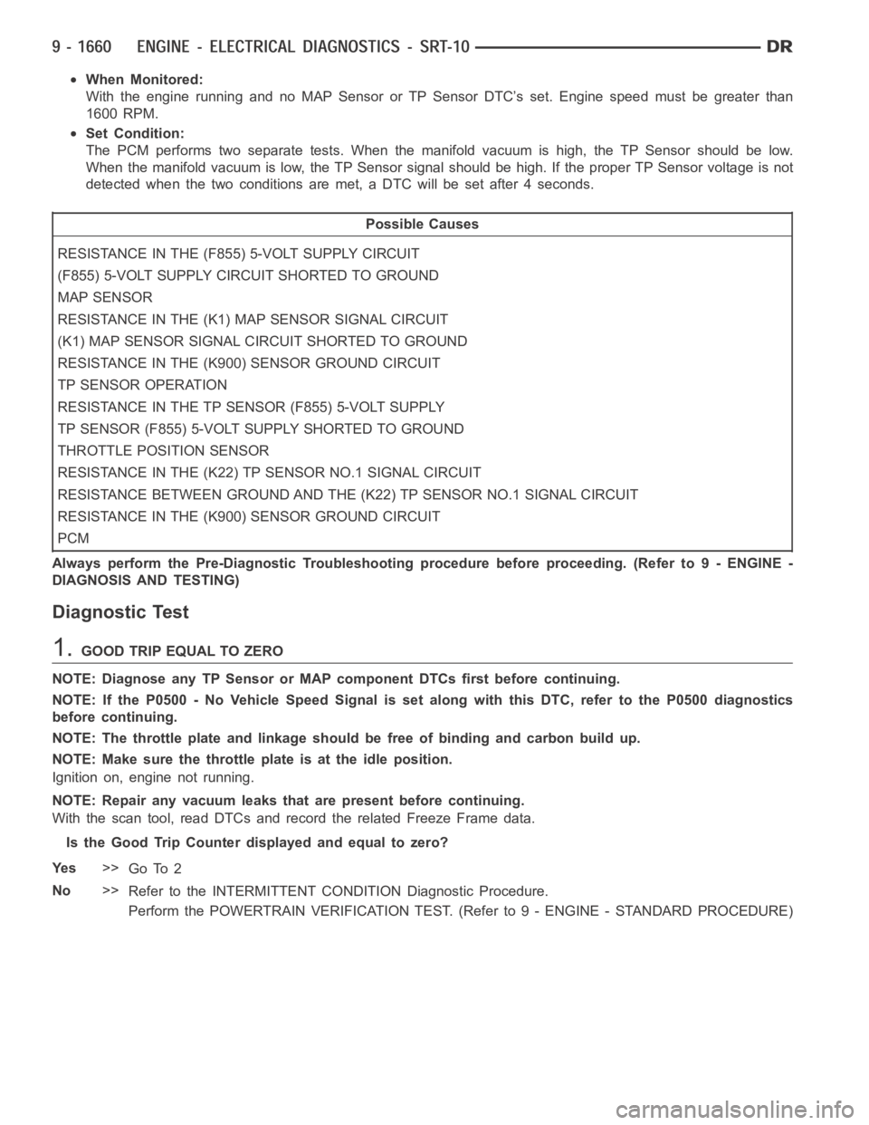
When Monitored:
With the engine running and no MAP Sensor or TP Sensor DTC’s set. Engine speed must be greater than
1600 RPM.
Set Condition:
The PCM performs two separate tests. When the manifold vacuum is high, the TP Sensor should be low.
When the manifold vacuum is low, the TP Sensor signal should be high. If the proper TP Sensor voltage is not
detected when the two conditions are met, a DTC will be set after 4 seconds.
Possible Causes
RESISTANCE IN THE (F855) 5-VOLT SUPPLY CIRCUIT
(F855) 5-VOLT SUPPLY CIRCUIT SHORTED TO GROUND
MAP SENSOR
RESISTANCE IN THE (K1) MAP SENSOR SIGNAL CIRCUIT
(K1) MAP SENSOR SIGNAL CIRCUIT SHORTED TO GROUND
RESISTANCE IN THE (K900) SENSOR GROUND CIRCUIT
TP SENSOR OPERATION
RESISTANCE IN THE TP SENSOR (F855) 5-VOLT SUPPLY
TP SENSOR (F855) 5-VOLT SUPPLY SHORTED TO GROUND
THROTTLE POSITION SENSOR
RESISTANCE IN THE (K22) TP SENSOR NO.1 SIGNAL CIRCUIT
RESISTANCE BETWEEN GROUND AND THE (K22) TP SENSOR NO.1 SIGNAL CIRCUIT
RESISTANCE IN THE (K900) SENSOR GROUND CIRCUIT
PCM
Always perform the Pre-Diagnostic Troubleshooting procedure before proceeding. (Refer to 9 - ENGINE -
DIAGNOSIS AND TESTING)
Diagnostic Test
1.GOOD TRIP EQUAL TO ZERO
NOTE: Diagnose any TP Sensor or MAP component DTCs first before continuing.
NOTE: If the P0500 - No Vehicle Speed Signal is set along with this DTC, referto the P0500 diagnostics
before continuing.
NOTE: The throttle plate and linkage should be free of binding and carbon build up.
NOTE: Make sure the throttle plate is at the idle position.
Ignition on, engine not running.
NOTE: Repair any vacuum leaks that are present before continuing.
With the scan tool, read DTCs and record the related Freeze Frame data.
Is the Good Trip Counter displayed and equal to zero?
Ye s>>
Go To 2
No>>
Refer to the INTERMITTENT CONDITION Diagnostic Procedure.
Perform the POWERTRAIN VERIFICATION TEST. (Refer to 9 - ENGINE - STANDARD PROCEDURE)
Page 970 of 5267
2.MAP SENSOR OPERATION
Start the engine.
With the scan tool, monitor the MAP Sensor voltage.
Snap the throttle.
Does the scan tool display MAP voltage from below 2.0 volts at idle to above 3.5 volts at WOT?
Ye s>>
Go To 3
No>>
Go To 10
3.TP SENSOR OPERATION
Ignition on, engine not running.
With the scan tool, monitor the TP Sensor voltage while slowly depressing the throttle pedal from the idle position
to the wide open throttle position.
Does voltage start at approximately 0.8 of a volt and go above 3.5 volts witha smooth transition?
Ye s>>
Refer to the INTERMITTENT CONDITION Diagnostic Procedure. (Refer to 9 - ENGINE - DIAGNOSIS
AND TESTING)
Perform the POWERTRAIN VERIFICATION TEST. (Refer to 9 - ENGINE - STANDARD PROCEDURE)
No>>
Go To 4
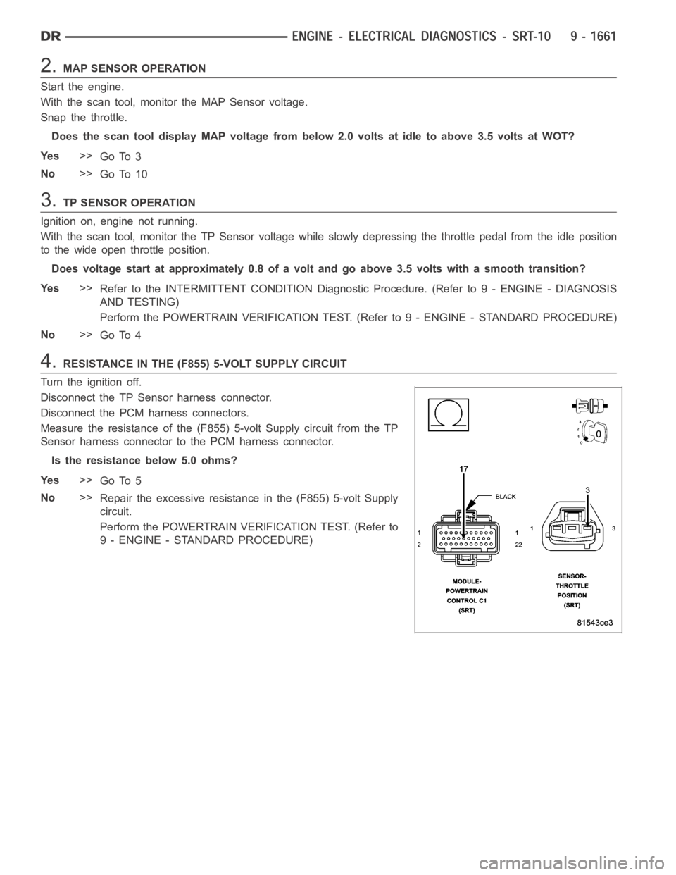
4.RESISTANCE IN THE (F855) 5-VOLT SUPPLY CIRCUIT
Turn the ignition off.
Disconnect the TP Sensor harness connector.
Disconnect the PCM harness connectors.
Measure the resistance of the (F855) 5-volt Supply circuit from the TP
Sensor harness connector to the PCM harness connector.
Is the resistance below 5.0 ohms?
Ye s>>
Go To 5
No>>
Repair the excessive resistance in the (F855) 5-volt Supply
circuit.
Perform the POWERTRAIN VERIFICATION TEST. (Refer to
9 - ENGINE - STANDARD PROCEDURE)
Page 1004 of 5267
When Monitored:
Ignition ON, with battery voltage greater than 10.4 volts.
Set Condition:
The state of the PCM relay control circuit, between the PCM and relay coil, does not match the desired state.
Possible Causes
O2 SENSOR HEATER RELAY
(K343) FUSED ASD RELAY OUTPUT CIRCUIT
(K127) O2 HEATER RELAY CONTROL CIRCUIT OPEN
(K127) O2 HEATER RELAY CONTROL CIRCUIT SHORTED TO GROUND
O2 SENSOR
PCM
Always perform the Pre-Diagnostic Troubleshooting procedure before proceeding. (Refer to 9 - ENGINE -
DIAGNOSIS AND TESTING)
1.GOOD TRIP EQUAL TO ZERO
Ignition on, engine not running.
With the Scan Tool, read DTCs and record the related Freeze Frame data.
Is the Good Trip Counter displayed and equal to zero?
Ye s>>
Go To 2
No>>
Refer to the INTERMITTENT CONDITION Diagnostic Procedure. (Refer to 9 - ENGINE - STANDARD
PROCEDURE)
2.O2 SENSOR HEATER RELAY
Turn the ignition off.
Remove the Heater Relay from the PDC.
Measurement is taken at the Heater Relay component.
Measure the resistance of the O2 Sensor Heater Relay Coil.
Is the resistance above 100 ohms?
Ye s>>
Replace the O2 Sensor Heater Relay.
Perform the POWERTRAIN VERIFICATION TEST. (Refer to 9 - ENGINE - STANDARD PROCEDURE)
No>>
Go To 3
3.(K344) FUSED ASD RELAY OUTPUT CIRCUIT
Ignition on, engine not running.
With the Scan Tool, actuate the ASD Relay.
Using a 12-volt test light connected to ground, probe the (K344) Fused ASD Relay Output circuit of the O2 Heater
Relay in the PDC.
Does the test light illuminate brightly when the relay actuates?
Ye s>>
Go To 4
No>>
Repair the open or short to ground in the ASD Relay Output circuit. Inspect the related fuse and repair
as necessary.
Perform the POWERTRAIN VERIFICATION TEST. (Refer to 9 - ENGINE - STANDARD PROCEDURE)
Page 1054 of 5267
Theory of Operation
The fuel feedback system will maintain a stoiciometric fuel/air mixture,14.7:1, by modifying the injector pulsewidth
according to the oxygen content of the exhaust gas. The PCM makes short termand long term fuel corrections to
maintain stoiciometric fuel/air ratio for best catalytic converter efficiency. Short term fuel correction is based on
upstream O2 sensor output and is designed for quick engine response. The long term fuel correction compensated
for variations in the engine specifications, sensor tolerances and component aging and is designed to correct rich
and lean conditions over a longer period of time.
When Monitored:
With the engine running in closed loop mode, the ambient/battery temperature above 20 deg. F and altitude
below 8500 ft.
Set Condition:
If the PCM multiplies short term compensation by long term adaptive and a certain percentage is exceeded for
two trips, a freeze frame is stored, the MIL illuminates and a trouble code is stored. Two Trip Fault. Three good
trips to turn off the MIL
Possible Causes
FUEL PRESSURE OUT OF SPECS
RESTRICTED FUEL SUPPLY LINE
FUEL PUMP INLET STRAINER PLUGGED
FUEL PUMP MODULE
O2 SENSOR
(K41) O2 SENSOR 1/1 SIGNAL CIRCUIT SHORTED TO GROUND
O2 SENSOR 1/1 HEATER OPERATION
TP SENSOR
MAP SENSOR
ECT SENSOR
ENGINE MECHANICAL CONDITION
FUEL FILTER/PRESSURE REGULATOR
PCM
Always perform the Pre-Diagnostic Troubleshooting procedure before proceeding. (Refer to 9 - ENGINE -
DIAGNOSIS AND TESTING).
Diagnostic Test
1.GOOD TRIP EQUAL TO ZERO
NOTE: Check for contaminates that may have damaged the O2 Sensor: contaminated fuel, unapproved sil-
icone, oil and coolant.
Ignition on, engine not running.
With the scan tool, read DTCs and record the related Freeze Frame data.
Is the Good Trip Counter displayed and equal to zero?
Ye s>>
Go To 2
No>>
Refer to the INTERMITTENT CONDITION Diagnostic Procedure.
Perform the POWERTRAIN VERIFICATION TEST. (Refer to 9 - ENGINE - STANDARD PROCEDURE)
Page 1061 of 5267
Theory of Operation
The fuel feedback system will maintain a stoiciometric fuel/air mixture,14.7:1, by modifying the injector pulsewidth
according to the oxygen content of the exhaust gas. The PCM makes short termand long term fuel corrections to
maintain stoiciometric fuel/air ratio for best catalytic converter efficiency. Short term fuel correction is based on
upstream O2 sensor output and is designed for quick engine response. The long term fuel correction compensated
for variations in the engine specifications, sensor tolerances and component aging and is designed to correct rich
and lean conditions over a longer period of time.
When Monitored:
With the engine running in closed loop mode, the ambient/battery temperature above 20 deg. F and altitude
below 8500 ft.
Set Condition:
If the PCM multiplies short term compensation by long term adaptive and a purge fuel multiplier and the result
is below a certain value for 30 seconds over two trips, a freeze frame is stored, the MIL illuminates and a
trouble code is stored. Two Trip Fault. Three good trips to turn off the MIL.
Possible Causes
O2 SENSOR
(K41) O2 SENSOR 1/1 SIGNAL CIRCUIT OPEN
(K41) O2 SENSOR 1/1 SIGNAL CIRCUIT SHORTED TO VOLTAGE
1/1 O2 SENSOR HEATER OPERATION
EVAP SYSTEM OPERATION
TP SENSOR VOLTAGE GREATER THAN 0.92 OF A VOLT WITH THROTTLE CLOSED
TP SENSOR
FUEL FILTER/PRESSURE REGULATOR
MAP SENSOR
ECT SENSOR
ENGINE MECHANICAL CONDITION
PCM
Always perform the Pre-Diagnostic Troubleshooting procedure before proceeding. (Refer to 9 - ENGINE -
DIAGNOSIS AND TESTING).
Diagnostic Test
1.GOOD TRIP EQUAL TO ZERO
NOTE: Check for contaminates that may have damaged the O2 Sensor: contaminated fuel, unapproved sil-
icone, oil and coolant.
Ignition on, engine not running.
With the scan tool, read DTCs and record the related Freeze Frame data.
NOTE: Any O2 Sensor, TPS, ECT, MAP, or EVAP DTCs must be repaired before continuing.
Is the Good Trip Counter displayed and equal to zero?
Ye s>>
Go To 2
No>>
Refer to the INTERMITTENT CONDITIONSymptom (Diagnostic Procedure).
Perform the POWERTRAIN VERIFICATION TEST. (Refer to 9 - ENGINE - STANDARD PROCEDURE)
Page 1067 of 5267
Theory of Operation
The fuel feedback system will maintain a stoiciometric fuel/air mixture,14.7:1, by modifying the injector pulsewidth
according to the oxygen content of the exhaust gas. The PCM makes short termand long term fuel corrections to
maintain stoiciometric fuel/air ratio for best catalytic converter efficiency. Short term fuel correction is based on
upstream O2 sensor output and is designed for quick engine response. The long term fuel correction compensated
for variations in the engine specifications, sensor tolerances and component aging and is designed to correct rich
and lean conditions over a longer period of time.
When Monitored:
With the engine running in closed loop mode, the ambient/battery temperature above 20 deg. F and altitude
below 8500 ft.
Set Condition:
If the PCM multiplies short term compensation by long term adaptive and a certain percentage is exceeded for
two trips, a freeze frame is stored, the MIL illuminates and a trouble code is stored. Two Trip Fault. Three good
trips to turn off the MIL.
Possible Causes
FUEL PRESSURE OUT OF SPECS
RESTRICTED FUEL SUPPLY LINE
FUEL PUMP INLET STRAINER PLUGGED
FUEL PUMP MODULE
O2 SENSOR
(K43) O2 SENSOR 2/1 SIGNAL CIRCUIT SHORTED TO GROUND
O2 SENSOR 2/1 HEATER OPERATION
TP SENSOR
MAP SENSOR
ECT SENSOR
ENGINE MECHANICAL CONDITION
FUEL FILTER/PRESSURE REGULATOR
PCM
Always perform the Pre-Diagnostic Troubleshooting procedure before proceeding. (Refer to 9 - ENGINE -
DIAGNOSIS AND TESTING).
Diagnostic Test
1.GOOD TRIP EQUAL TO ZERO
NOTE: Check for contaminates that may have damaged the O2 Sensor: contaminated fuel, unapproved sil-
icone, oil and coolant.
Ignition on, engine not running.
With the scan tool, read DTCs and record the related Freeze Frame data.
Is the Good Trip Counter displayed and equal to zero?
Ye s>>
Go To 2
No>>
Refer to the INTERMITTENT CONDITION Diagnostic Procedure.
Perform the POWERTRAIN VERIFICATION TEST. (Refer to 9 - ENGINE - STANDARD PROCEDURE)
Page 1074 of 5267

Theory of Operation
The fuel feedback system will maintain a stoiciometric fuel/air mixture,14.7:1, by modifying the injector pulsewidth
according to the oxygen content of the exhaust gas. The PCM makes short termand long term fuel corrections to
maintain stoiciometric fuel/air ratio for best catalytic converter efficiency. Short term fuel correction is based on
upstream O2 sensor output and is designed for quick engine response. The long term fuel correction compensated
for variations in the engine specifications, sensor tolerances and component aging and is designed to correct rich
and lean conditions over a longer period of time.
When Monitored:
With the engine running in closed loop mode, the ambient/battery temperature above 20 deg. F and altitude
below 8500 ft.
Set Condition:
If the PCM multiplies short term compensation by long term adaptive and a purge fuel multiplier and the result
is below a certain value for 30 seconds over two trips, a freeze frame is stored, the MIL illuminates and a
trouble code is stored. Two Trip Fault. Three good trips to turn off the MIL.
Possible Causes
O2 SENSOR
(K43) O2 SENSOR 2/1 SIGNAL CIRCUIT OPEN
(K43) O2 SENSOR 2/1 SIGNAL CIRCUIT SHORTED TO VOLTAGE
2/1 O2 SENSOR HEATER OPERATION
EVAP SYSTEM OPERATION
TP SENSOR VOLTAGE GREATER THAN 0.92 OF A VOLT WITH THROTTLE CLOSED
TP SENSOR
FUEL FILTER/PRESSURE REGULATOR
MAP SENSOR
ECT SENSOR
ENGINE MECHANICAL CONDITION
PCM
Always perform the Pre-Diagnostic Troubleshooting procedure before proceeding. (Refer to 9 - ENGINE -
DIAGNOSIS AND TESTING).
Diagnostic Test
1.GOOD TRIP EQUAL TO ZERO
NOTE: Check for contaminates that may have damaged the O2 Sensor: contaminated fuel, unapproved sil-
icone, oil and coolant.
Ignition on, engine not running.
With the scan tool, read DTCs and record the related Freeze Frame data.
NOTE: Any O2 Sensor, TPS, ECT, MAP, or EVAP DTCs must be repaired before continuing.
Is the Good Trip Counter displayed and equal to zero?
Ye s>>
Go To 2
No>>
Refer to the INTERMITTENT CONDITIONSymptom (Diagnostic Procedure).
Perform the POWERTRAIN VERIFICATION TEST. (Refer to 9 - ENGINE - STANDARD PROCEDURE)
Page 1233 of 5267
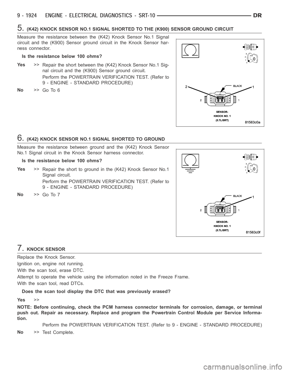
5.(K42) KNOCK SENSOR NO.1 SIGNAL SHORTED TO THE (K900) SENSOR GROUND CIRCUIT
Measure the resistance between the (K42) Knock Sensor No.1 Signal
circuit and the (K900) Sensor ground circuit in the Knock Sensor har-
ness connector.
Istheresistancebelow100ohms?
Ye s>>
Repair the short between the (K42) Knock Sensor No.1 Sig-
nal circuit and the (K900) Sensor ground circuit.
Perform the POWERTRAIN VERIFICATION TEST. (Refer to
9 - ENGINE - STANDARD PROCEDURE)
No>>
Go To 6
6.(K42) KNOCK SENSOR NO.1 SIGNAL SHORTED TO GROUND
Measure the resistance between ground and the (K42) Knock Sensor
No.1 Signal circuit in the Knock Sensor harness connector.
Istheresistancebelow100ohms?
Ye s>>
Repair the short to ground in the (K42) Knock Sensor No.1
Signal circuit.
Perform the POWERTRAIN VERIFICATION TEST. (Refer to
9 - ENGINE - STANDARD PROCEDURE)
No>>
Go To 7
7.KNOCK SENSOR
Replace the Knock Sensor.
Ignition on, engine not running.
With the scan tool, erase DTC.
Attempt to operate the vehicle using the information noted in the Freeze Frame.
With the scan tool, read DTCs.
Does the scan tool display the DTC that was previously erased?
Ye s>>
NOTE: Before continuing, check the PCM harness connector terminals for corrosion, damage, or terminal
push out. Repair as necessary. Replace and program the Powertrain ControlModule per Service Informa-
tion.
Perform the POWERTRAIN VERIFICATION TEST. (Refer to 9 - ENGINE - STANDARD PROCEDURE)
No>>
Te s t C o m p l e t e .