2006 DODGE RAM SRT-10 display
[x] Cancel search: displayPage 1407 of 5267
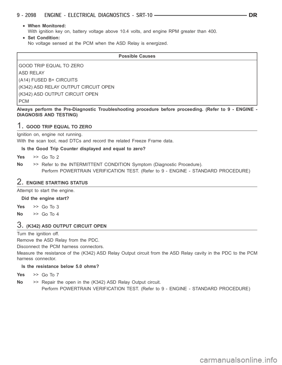
When Monitored:
With ignition key on, battery voltage above 10.4 volts, and engine RPM greater than 400.
Set Condition:
No voltage sensed at the PCM when the ASD Relay is energized.
Possible Causes
GOOD TRIP EQUAL TO ZERO
ASD RELAY
(A14) FUSED B+ CIRCUITS
(K342) ASD RELAY OUTPUT CIRCUIT OPEN
(K342) ASD OUTPUT CIRCUIT OPEN
PCM
Always perform the Pre-Diagnostic Troubleshooting procedure before proceeding. (Refer to 9 - ENGINE -
DIAGNOSIS AND TESTING)
1.GOOD TRIP EQUAL TO ZERO
Ignition on, engine not running.
With the scan tool, read DTCs and record the related Freeze Frame data.
Is the Good Trip Counter displayed and equal to zero?
Ye s>>
Go To 2
No>>
Refer to the INTERMITTENT CONDITIONSymptom (Diagnostic Procedure).
Perform POWERTRAIN VERIFICATION TEST. (Refer to 9 - ENGINE - STANDARD PROCEDURE)
2.ENGINE STARTING STATUS
Attempt to start the engine.
Did the engine start?
Ye s>>
Go To 3
No>>
Go To 4
3.(K342) ASD OUTPUT CIRCUIT OPEN
Turn the ignition off.
Remove the ASD Relay from the PDC.
Disconnect the PCM harness connectors.
Measure the resistance of the (K342) ASD Relay Output circuit from the ASD Relay cavity in the PDC to the PCM
harness connector.
Is the resistance below 5.0 ohms?
Ye s>>
Go To 7
No>>
Repair the open in the (K342)ASD Relay Output circuit.
Perform POWERTRAIN VERIFICATION TEST. (Refer to 9 - ENGINE - STANDARD PROCEDURE)
Page 1416 of 5267
When Monitored:
Immediately after a cold start, with battery/ambient temperature between 40 deg. F and 90 Deg. F and coolant
temperature within 10 Deg. F of battery/ambient.
Set Condition:
LDP test must pass first. If the PCM suspects a pinched hose it will not set a fault until it runs the EVAP purge
flow monitor. If the purge monitor does not pass then the pinched hose faultwill be set.
Possible Causes
EVAP CANISTER OBSTRUCTED
OBSTRUCTION IN HOSE/TUBE BETWEEN EVAP CANISTER AND PURGE SOLENOID
LDP PRESSURE HOSE OBSTRUCTED
LEAK DETECTION PUMP
Always perform the Pre-Diagnostic Troubleshooting procedure before proceeding. (Refer to 9 - ENGINE -
DIAGNOSIS AND TESTING)
Diagnostic Test
1.VEHICLE HISTORY AND SERVICE BULLETIN INVESTIGATION
Ignition on, engine not running.
With a scan tool, read DTCs and record the related Freeze Frame data if any DTC(s) are present.
Whether or not any DTC(s) are present you will want to check the following items which may assist in repairing the
customer’s complaint successfully.
Check the vehicles repair history.
If the vehicle has a repair history that pertains to the customer’s currentcomplaint, review the repair.
Inspect the vehicle for any aftermarket accessories that may have been installed incorrectly.
Check for any service bulletin(s) related to the customer’s complaint or DTC(s).
If a service bulletin applies, follow the instructions per the service bulletin.
Choose the following scenario that best applies.
The service bulletin repaired the customer’s complaint.
Testing complete.
A DTC is present, no service bulletins apply, or the service bulletin didn’t repair the customer’s complaint.
Go To 2
2.GOOD TRIP EQUAL TO ZERO
Ignition on, engine not running.
With the scan tool, read DTCs.
Is the Good Trip Counter displayed and equal to zero?
Ye s>>
Go To 3
No>>
Go To 8
Page 1427 of 5267
When Monitored:
Immediately after a cold start, with battery/ambient temperature between 40 Deg. F and 90 Deg. F and coolant
temperature within 10 Deg. F of battery/ambient.
Set Condition:
The state of the switch does not change when the solenoid is energized.
Possible Causes
GOOD TRIP EQUAL TO ZERO
LDP VACUUM SUPPLY
LEAK DETECTION PUMP
(K107) LDP SWITCH SENSE CIRCUIT OPEN
(K107) LDP SWITCH SENSE CIRCUIT SHORTED TO GROUND
PCM
Always perform the Pre-Diagnostic Troubleshooting procedure before proceeding. (Refer to 9 - ENGINE -
DIAGNOSIS AND TESTING)
Diagnostic Test
1.VEHICLE HISTORY AND SERVICE BULLETIN INVESTIGATION
Ignition on, engine not running.
With a scan tool, read DTCs and record the related Freeze Frame data if any DTC(s) are present.
Whether or not any DTC(s) are present you will want to check the following items which may assist in repairing the
customer’s complaint successfully.
Check the vehicles repair history.
If the vehicle has a repair history that pertains to the customer’s currentcomplaint, review the repair.
Inspect the vehicle for any aftermarket accessories that may have been installed incorrectly.
Check for any service bulletin(s) related to the customer’s complaint or DTC(s).
If a service bulletin applies, follow the instructions per the service bulletin.
Choose the following scenario that best applies.
The service bulletin repaired the customer’s complaint.
Testing complete.
A DTC is present, no service bulletins apply, or the service bulletin didn’t repair the customer’s complaint.
Go To 2
2.GOOD TRIP EQUAL TO ZERO
Check for any related TSBs.
Ignition on, engine not running.
With the scan tool, read DTCs and record the related Freeze Frame data.
Is the Good Trip Counter displayed and equal to zero?
Ye s>>
Go To 3
No>>
Refer to the INTERMITTENT CONDITION Diagnostic Procedure.
Perform POWERTRAIN VERIFICATION TEST. (Refer to 9 - ENGINE - STANDARD PROCEDURE)
Page 1431 of 5267
When Monitored:
Continuously when the ignition is on and battery voltage is greater than 10.4 volts.
Set Condition:
The state of the solenoid circuit does not match the PCM’s desired state.
Possible Causes
(K125) GENERATOR SOURCE CIRCUIT OPEN
(K107) LDP SWITCH SIGNAL CIRCUIT OPEN
(K107) LDP SWITCH SIGNAL CIRCUIT SHORTED TO GROUND
(K106) LEAK DETECTION PUMP SOLENOID CONTROL CIRCUIT OPEN
(K106) LDP SOLENOID CONTROL CIRCUIT SHORTED TO GROUND
LEAK DETECTION PUMP
PCM
Always perform the Pre-Diagnostic Troubleshooting procedure before proceeding. (Refer to 9 - ENGINE -
DIAGNOSIS AND TESTING)
Diagnostic Test
1.VEHICLE HISTORY AND SERVICE BULLETIN INVESTIGATION
Ignition on, engine not running.
With a scan tool, read DTCs and record the related Freeze Frame data if any DTC(s) are present.
Whether or not any DTC(s) are present you will want to check the following items which may assist in repairing the
customer’s complaint successfully.
Check the vehicles repair history.
If the vehicle has a repair history that pertains to the customer’s currentcomplaint, review the repair.
Inspect the vehicle for any aftermarket accessories that may have been installed incorrectly.
Check for any service bulletin(s) related to the customer’s complaint or DTC(s).
If a service bulletin applies, follow the instructions per the service bulletin.
Choose the following scenario that best applies.
The service bulletin repaired the customer’s complaint.
Testing complete.
A DTC is present, no service bulletins apply, or the service bulletin didn’t repair the customer’s complaint.
Go To 2
2.GOOD TRIP EQUAL TO ZERO
Ignition on, engine not running.
With the scan tool, read DTCs.
Is the Good Trip Counter displayed and equal to zero?
Ye s>>
Go To 3
No>>
Refer to the INTERMITTENT CONDITION Diagnostic Procedure.
Perform POWERTRAIN VERIFICATION TEST. (Refer to 9 - ENGINE - STANDARD PROCEDURE)
Page 1456 of 5267
When Monitored:
With the ignition on.
Set Condition:
The PCM has not received an expected Cluster Status Bus message from the instrument cluster within the last
20 seconds.
Possible Causes
(D25) OPEN BETWEEN PCM AND CLUSTER
(D25) SHORTED BETWEEN PCM AND CLUSTER
CLUSTER
PCM
Always perform the Pre-Diagnostic Troubleshooting procedure before proceeding. (Refer to 9 - ENGINE -
DIAGNOSIS AND TESTING)
Diagnostic Test
1.NO CLUSTER BUS MESSAGE
Ignition on, engine not running.
With the scan tool, erase DTCs.
Cycle the ignition key on and off several times.
With the scan tool, read DTCs.
Does the DTC reset?
Ye s>>
Go To 2
No>>
Refer to the INTERMITTENT CONDITION Diagnostic Procedure.
Perform the POWERTRAIN VERIFICATION TEST. (Refer to 9 - ENGINE - STANDARD PROCEDURE)
2.COMMUNICATE WITH CLUSTER
Ignition on, engine not running.
With the scan tool, attempt to communicate with the Instrument cluster.
Can communication be established with the Instrument Cluster?
Ye s>>
Go To 3
No>>
Refer to the Communication Category of the Body Diagnostic Manual and perform the appropriate
symptom related to no communication with cluster.
Perform the POWERTRAIN VERIFICATION TEST. (Refer to 9 - ENGINE - STANDARD PROCEDURE)
3.INSTRUMENT CLUSTER OPERATION
Start the engine
Allow the engine to idle.
Is the correct engine speed display in the instrument cluster (Tach)?
Ye s>>
Replace and program the Powertrain Control Module per Service Information.
Perform the POWERTRAIN VERIFICATION TEST. (Refer to 9 - ENGINE - STANDARD PROCEDURE)
No>>
Refer to the Instrument Category in the Body Diagnostic Manual and performthe appropriate symptom.
Perform the POWERTRAIN VERIFICATION TEST. (Refer to 9 - ENGINE - STANDARD PROCEDURE)
Page 1460 of 5267
P1696-PCM FAILURE EEPROM WRITE DENIED
For a complete wiring diagramRefer to Section 8W.
When Monitored:
Ignition on and battery voltage greater than 10 volts.
Set Condition:
An attempt to program/write to the internal EEPROM failed, also checks at powerdown.
Possible Causes
SRI MILEAGE INVALID
PCM
Always perform the Pre-Diagnostic Troubleshooting procedure before proceeding. (Refer to 9 - ENGINE -
DIAGNOSIS AND TESTING)
Diagnostic Test
1.SCAN TOOL DISPLAYS WRITE FAILURE
Ignition on, engine not running.
With the scan tool, perform the SRI Memory Test.
Does the scan tool display Write Failure?
Ye s>>
Replace and program the Powertrain Control Module per Service Information.
Perform the POWERTRAIN VERIFICATION TEST. (Refer to 9 - ENGINE - STANDARD PROCEDURE)
No>>
Go To 2
2.SCAN TOOL DISPLAYS WRITE REFUSED
With the scan tool, perform the SRI Memory Test.
Does the scan tool display Write Refused?
Ye s>>
Go To 3
No>>
Go To 4
3.PCM REFUSED 2ND TEST
With the scan tool, perform the SRI Memory Test a second time.
NOTE: Retest the SRI Memory two more times.
Does the scan tool display Write Refused again?
Ye s>>
Replace and program the Powertrain Control Module per Service Information.
Perform the POWERTRAIN VERIFICATION TEST. (Refer to 9 - ENGINE - STANDARD PROCEDURE)
No>>
Te s t C o m p l e t e .
4.SCAN TOOL DISPLAYS SRI MILEAGE INVALID
With the scan tool, perform the SRI Memory Test.
Does the scan tool display SRI Mileage Invalid?
Ye s>>
Update the mileage and retest the SRI Memory.
Perform the POWERTRAIN VERIFICATION TEST. (Refer to 9 - ENGINE - STANDARD PROCEDURE)
No>>
Go To 5
Page 1461 of 5267

5.COMPARE SRI MILEAGE WITH ODOMETER
Compare the SRI Mileage stored with the Instrument Panel Odometer.
Is the mileage within the specified range displayed on the scan tool?
Ye s>>
Te s t C o m p l e t e .
No>>
Update the mileage and retest the SRI Memory.
Perform the POWERTRAIN VERIFICATION TEST. (Refer to 9 - ENGINE - STANDARD PROCEDURE)
Page 1463 of 5267
Possible Causes
(A103) FUSED B+ CIRCUIT
(Z429) BRAKE LAMP SWITCH GROUND CIRCUIT OPEN
BRAKE LAMP SWITCH
(B29) BRAKE SWITCH NO.1 SIGNAL CIRCUIT OPEN
(B29) BRAKE SWITCH NO.1 SIGNAL CIRCUIT SHORT TO GROUND
PCM
Always perform the Pre-Diagnostic Troubleshooting procedure before proceeding. (Refer to 9 - ENGINE -
DIAGNOSIS AND TESTING)
Diagnostic Test
1.SCAN TOOL DOES NOT SHOW BRAKE SW PRESSED OR RELEASED
Ignition on, engine not running.
With the scan tool in Inputs/Outputs, read the Brake Switch state.
While observing the scan tool display, press and release the brake pedal several times.
Does the scan tool display Brake Switch PRESSED and RELEASED?
Ye s>>
The Brake Lamp Switch is operating properly at this time.
Perform the POWERTRAIN VERIFICATION TEST. (Refer to 9 - ENGINE - STANDARD PROCEDURE)
No>>
Go To 2
2.(A103) FUSED B+ CIRCUIT OPEN
Turn the ignition off.
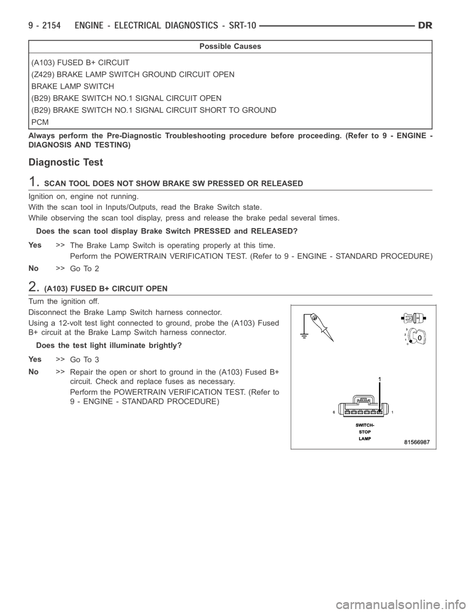
Disconnect the Brake Lamp Switch harness connector.
Using a 12-volt test light connected to ground, probe the (A103) Fused
B+ circuit at the Brake Lamp Switch harness connector.
Does the test light illuminate brightly?
Ye s>>
Go To 3
No>>
Repair the open or short to ground in the (A103) Fused B+
circuit. Check and replace fuses as necessary.
Perform the POWERTRAIN VERIFICATION TEST. (Refer to
9 - ENGINE - STANDARD PROCEDURE)