2006 DODGE RAM SRT-10 display
[x] Cancel search: displayPage 3362 of 5267
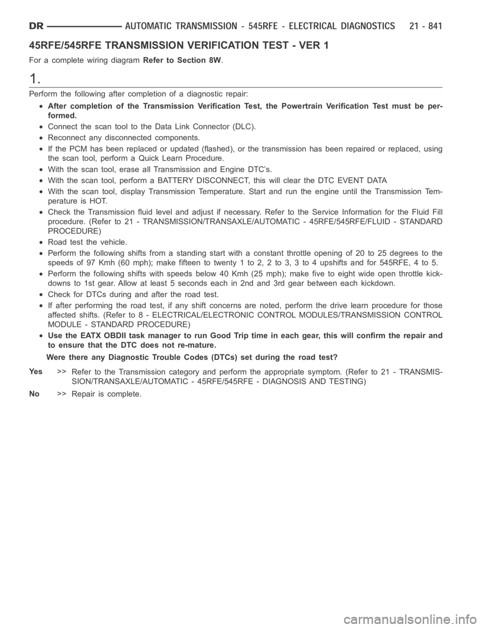
45RFE/545RFE TRANSMISSION VERIFICATION TEST - VER 1
For a complete wiring diagramRefer to Section 8W.
1.
Perform the following after completion of a diagnostic repair:
After completion of the Transmission Verification Test, the Powertrain Verification Test must be per-
formed.
Connect the scan tool to the Data Link Connector (DLC).
Reconnect any disconnected components.
If the PCM has been replaced or updated (flashed), or the transmission has been repaired or replaced, using
the scan tool, perform a Quick Learn Procedure.
With the scan tool, erase all Transmission and Engine DTC’s.
With the scan tool, perform a BATTERY DISCONNECT, this will clear the DTC EVENT DATA
With the scan tool, display Transmission Temperature. Start and run the engine until the Transmission Tem-
perature is HOT.
Check the Transmission fluid level and adjust if necessary. Refer to the Service Information for the Fluid Fill
procedure. (Refer to 21 - TRANSMISSION/TRANSAXLE/AUTOMATIC - 45RFE/545RFE/FLUID - STANDARD
PROCEDURE)
Road test the vehicle.
Perform the following shifts from a standing start with a constant throttle opening of 20 to 25 degrees to the
speeds of 97 Kmh (60 mph); make fifteen to twenty 1 to 2, 2 to 3, 3 to 4 upshifts andfor545RFE,4to5.
Perform the following shifts with speeds below 40 Kmh (25 mph); make five toeight wide open throttle kick-
downs to 1st gear. Allow at least 5 seconds each in 2nd and 3rd gear between each kickdown.
Check for DTCs during and after the road test.
If after performing the road test, if any shift concerns are noted, performthe drive learn procedure for those
affected shifts. (Refer to 8 - ELECTRICAL/ELECTRONIC CONTROL MODULES/TRANSMISSION CONTROL
MODULE - STANDARD PROCEDURE)
Use the EATX OBDII task manager to run Good Trip time in each gear, this will confirm the repair and
to ensure that the DTC does not re-mature.
Were there any Diagnostic Trouble Codes (DTCs) set during the road test?
Ye s>>
Refer to the Transmission category and perform the appropriate symptom. (Refer to 21 - TRANSMIS-
SION/TRANSAXLE/AUTOMATIC - 45RFE/545RFE - DIAGNOSIS AND TESTING)
No>>
Repair is complete.
Page 3567 of 5267
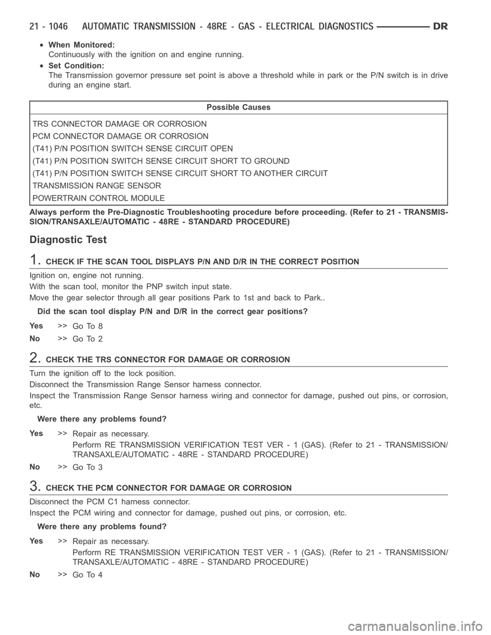
When Monitored:
Continuously with the ignition on and engine running.
Set Condition:
The Transmission governor pressure set point is above a threshold while inparkortheP/Nswitchisindrive
during an engine start.
Possible Causes
TRS CONNECTOR DAMAGE OR CORROSION
PCM CONNECTOR DAMAGE OR CORROSION
(T41) P/N POSITION SWITCH SENSE CIRCUIT OPEN
(T41) P/N POSITION SWITCH SENSE CIRCUIT SHORT TO GROUND
(T41) P/N POSITION SWITCH SENSE CIRCUIT SHORT TO ANOTHER CIRCUIT
TRANSMISSION RANGE SENSOR
POWERTRAIN CONTROL MODULE
Always perform the Pre-Diagnostic Troubleshooting procedure before proceeding. (Refer to 21 - TRANSMIS-
SION/TRANSAXLE/AUTOMATIC - 48RE - STANDARD PROCEDURE)
Diagnostic Test
1.CHECK IF THE SCAN TOOL DISPLAYS P/N AND D/R IN THE CORRECT POSITION
Ignition on, engine not running.
With the scan tool, monitor the PNP switch input state.
Move the gear selector through all gear positions Park to 1st and back to Park..
Did the scan tool display P/N and D/R in the correct gear positions?
Ye s>>
Go To 8
No>>
Go To 2
2.CHECK THE TRS CONNECTOR FOR DAMAGE OR CORROSION
Turn the ignition off to the lock position.
Disconnect the Transmission Range Sensor harness connector.
Inspect the Transmission Range Sensor harness wiring and connector for damage, pushed out pins, or corrosion,
etc.
Were there any problems found?
Ye s>>
Repair as necessary.
Perform RE TRANSMISSION VERIFICATION TEST VER - 1 (GAS). (Refer to 21 - TRANSMISSION/
TRANSAXLE/AUTOMATIC - 48RE - STANDARD PROCEDURE)
No>>
Go To 3
3.CHECK THE PCM CONNECTOR FOR DAMAGE OR CORROSION
Disconnect the PCM C1 harness connector.
Inspect the PCM wiring and connector for damage, pushed out pins, or corrosion, etc.
Were there any problems found?
Ye s>>
Repair as necessary.
Perform RE TRANSMISSION VERIFICATION TEST VER - 1 (GAS). (Refer to 21 - TRANSMISSION/
TRANSAXLE/AUTOMATIC - 48RE - STANDARD PROCEDURE)
No>>
Go To 4
Page 3569 of 5267
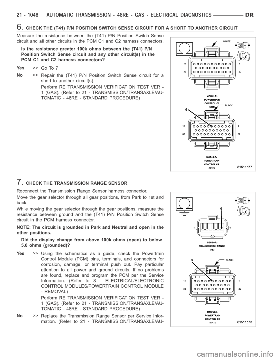
6.CHECK THE (T41) P/N POSITION SWITCH SENSE CIRCUIT FOR A SHORT TO ANOTHER CIRCUIT
Measure the resistance between the (T41) P/N Position Switch Sense
circuit and all other circuits in the PCM C1 and C2 harness connectors.
Is the resistance greater 100k ohms between the (T41) P/N
Position Switch Sense circuitand any other circuit(s) in the
PCM C1 and C2 harness connectors?
Ye s>>
Go To 7
No>>
Repair the (T41) P/N Position Switch Sense circuit for a
short to another circuit(s).
Perform RE TRANSMISSION VERIFICATION TEST VER -
1 (GAS). (Refer to 21 - TRANSMISSION/TRANSAXLE/AU-
TOMATIC - 48RE - STANDARD PROCEDURE)
7.CHECK THE TRANSMISSION RANGE SENSOR
Reconnect the Transmission Range Sensor harness connector.
Move the gear selector through all gear positions, from Park to 1st and
back.
While moving the gear selector through the gear positions, measure the
resistance between ground and the (T41) P/N Position Switch Sense
circuit in the PCM harness connector.
NOTE: The circuit is grounded in Park and Neutral and open in the
other positions.
Did the display change from above 100k ohms (open) to below
5.0 ohms (grounded)?
Ye s>>
Using the schematics as a guide, check the Powertrain
Control Module (PCM) pins, terminals, and connectors for
corrosion, damage, or terminal push out. Pay particular
attention to all power and ground circuits. If no problems
are found, replace and program the PCM per the Service
Information. (Refer to 8 - ELECTRICAL/ELECTRONIC
CONTROL MODULES/POWERTRAIN CONTROL MODULE
- REMOVAL)
Perform RE TRANSMISSION VERIFICATION TEST VER -
1 (GAS). (Refer to 21 - TRANSMISSION/TRANSAXLE/AU-
TOMATIC - 48RE - STANDARD PROCEDURE)
No>>
Replace the Transmission Range Sensor per Service Infor-
mation. (Refer to 21 - TRANSMISSION/TRANSAXLE/AU-
Page 3585 of 5267
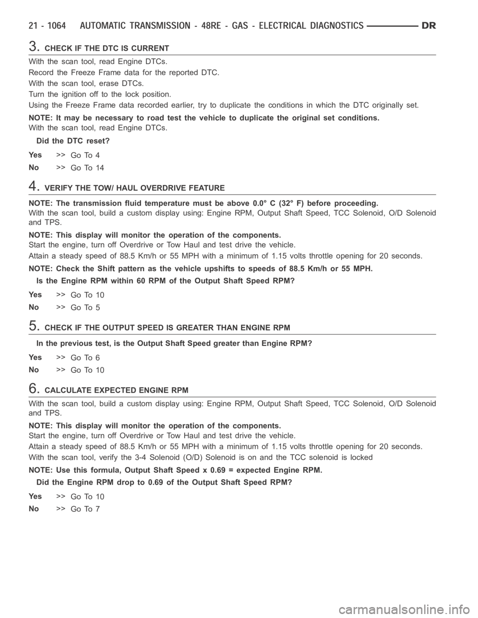
3.CHECK IF THE DTC IS CURRENT
With the scan tool, read Engine DTCs.
Record the Freeze Frame data for the reported DTC.
With the scan tool, erase DTCs.
Turn the ignition off to the lock position.
Using the Freeze Frame data recorded earlier, try to duplicate the conditions in which the DTC originally set.
NOTE: It may be necessary to road test the vehicle to duplicate the originalset conditions.
With the scan tool, read Engine DTCs.
Did the DTC reset?
Ye s>>
Go To 4
No>>
Go To 14
4.VERIFY THE TOW/ HAUL OVERDRIVE FEATURE
NOTE: The transmission fluid temperature must be above 0.0° C (32° F) before proceeding.
With the scan tool, build a custom display using: Engine RPM, Output Shaft Speed, TCC Solenoid, O/D Solenoid
and TPS.
NOTE: This display will monitor the operation of the components.
Start the engine, turn off Overdrive or Tow Haul and test drive the vehicle.
Attain a steady speed of 88.5 Km/h or 55 MPH with a minimum of 1.15 volts throttle opening for 20 seconds.
NOTE: Check the Shift pattern as the vehicle upshifts to speeds of 88.5 Km/hor 55 MPH.
Is the Engine RPM within 60 RPM of the Output Shaft Speed RPM?
Ye s>>
Go To 10
No>>
Go To 5
5.CHECK IF THE OUTPUT SPEED IS GREATER THAN ENGINE RPM
In the previous test, is the Output Shaft Speed greater than Engine RPM?
Ye s>>
Go To 6
No>>
Go To 10
6.CALCULATE EXPECTED ENGINE RPM
With the scan tool, build a custom display using: Engine RPM, Output Shaft Speed, TCC Solenoid, O/D Solenoid
and TPS.
NOTE: This display will monitor the operation of the components.
Start the engine, turn off Overdrive or Tow Haul and test drive the vehicle.
Attain a steady speed of 88.5 Km/h or 55 MPH with a minimum of 1.15 volts throttle opening for 20 seconds.
With the scan tool, verify the 3-4 Solenoid (O/D) Solenoid is on and the TCC solenoid is locked
NOTE: Use this formula, Output Shaft Speed x 0.69 = expected Engine RPM.
Did the Engine RPM drop to 0.69 of the Output Shaft Speed RPM?
Ye s>>
Go To 10
No>>
Go To 7
Page 3660 of 5267

When Monitored:
Continuously with the ignition on and engine running.
Set Condition:
The Transmission governor pressure set point is above a threshold while inparkortheP/Nswitchisindrive
during an engine start.
Possible Causes
TRS CONNECTOR DAMAGE OR CORROSION
ECM CONNECTOR DAMAGE OR CORROSION
(T41) P/N POSITION SWITCH SENSE CIRCUIT OPEN
(T41) P/N POSITION SWITCH SENSE CIRCUIT SHORT TO GROUND
(T41) P/N POSITION SWITCH SENSE CIRCUIT SHORT TO ANOTHER CIRCUIT
TRANSMISSION RANGE SENSOR
ENGINE CONTROL MODULE
Always perform the Pre-Diagnostic Troubleshooting procedure before proceeding. (Refer to 21 - TRANSMIS-
SION/TRANSAXLE/AUTOMATIC - 48RE - STANDARD PROCEDURE)
Diagnostic Test
1.CHECK IF THE SCAN TOOL DISPLAYS P/N AND D/R IN THE CORRECT POSITION
Ignition on, engine not running.
With the scan tool, monitor the PNP switch input state.
Move the gear selector through all gear positions Park to 1st and back to Park.
Did the scan tool display P/N and D/R in the correct gear positions?
Ye s>>
Go To 8
No>>
Go To 2
2.CHECK THE TRS CONNECTOR FOR DAMAGE OR CORROSION
Turn the ignition off to the lock position.
Disconnect the Transmission Range Sensor harness connector.
Inspect the Transmission Range Sensor harness wiring and connector for damage, pushed out pins, or corrosion,
etc.
Were there any problems found?
Ye s>>
Repair as necessary.
Perform RE TRANSMISSION VERIFICATION TEST VER - 1 (DIESEL). (Refer to 21 - TRANSMISSION/
TRANSAXLE/AUTOMATIC - 48RE - STANDARD PROCEDURE)
No>>
Go To 3
3.CHECK THE ECM CONNECTOR FOR DAMAGE OR CORROSION
Disconnect the ECM C2 harness connector.
Inspect the ECM wiring and connector for damage, pushed out pins, or corrosion, etc.
Were there any problems found?
Ye s>>
Repair as necessary.
Perform RE TRANSMISSION VERIFICATION TEST VER - 1 (DIESEL). (Refer to 21 - TRANSMISSION/
TRANSAXLE/AUTOMATIC - 48RE - STANDARD PROCEDURE)
No>>
Go To 4
Page 3662 of 5267
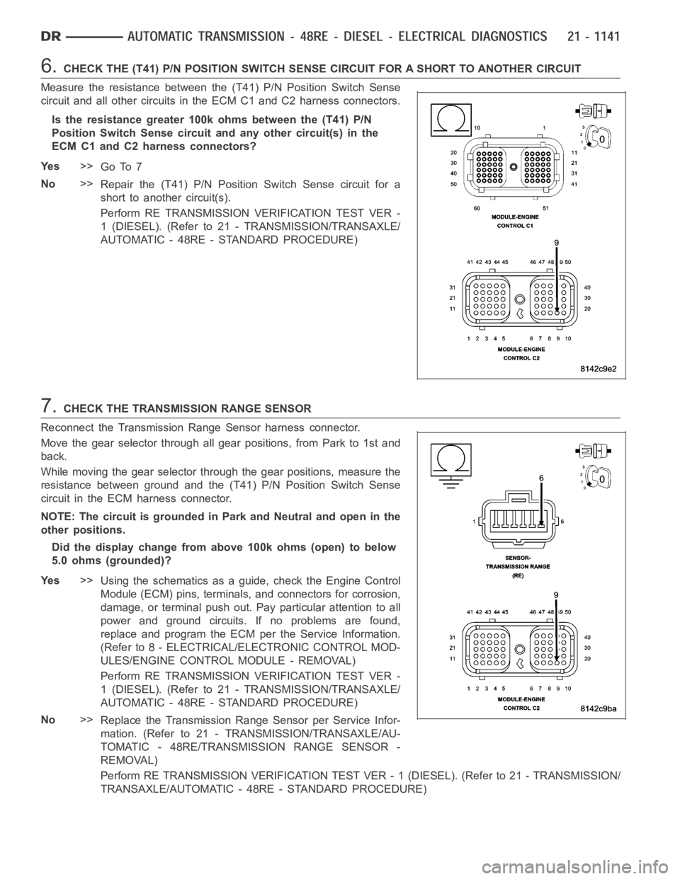
6.CHECK THE (T41) P/N POSITION SWITCH SENSE CIRCUIT FOR A SHORT TO ANOTHER CIRCUIT
Measure the resistance between the (T41) P/N Position Switch Sense
circuit and all other circuits in the ECM C1 and C2 harness connectors.
Is the resistance greater 100k ohms between the (T41) P/N
Position Switch Sense circuitand any other circuit(s) in the
ECM C1 and C2 harness connectors?
Ye s>>
Go To 7
No>>
Repair the (T41) P/N Position Switch Sense circuit for a
short to another circuit(s).
Perform RE TRANSMISSION VERIFICATION TEST VER -
1 (DIESEL). (Refer to 21 - TRANSMISSION/TRANSAXLE/
AUTOMATIC - 48RE - STANDARD PROCEDURE)
7.CHECK THE TRANSMISSION RANGE SENSOR
Reconnect the Transmission Range Sensor harness connector.
Move the gear selector through all gear positions, from Park to 1st and
back.
While moving the gear selector through the gear positions, measure the
resistance between ground and the (T41) P/N Position Switch Sense
circuit in the ECM harness connector.
NOTE: The circuit is grounded in Park and Neutral and open in the
other positions.
Did the display change from above 100k ohms (open) to below
5.0 ohms (grounded)?
Ye s>>
Using the schematics as a guide, check the Engine Control
Module (ECM) pins, terminals, and connectors for corrosion,
damage, or terminal push out. Pay particular attention to all
power and ground circuits. If no problems are found,
replace and program the ECM per the Service Information.
(Refer to 8 - ELECTRICAL/ELECTRONIC CONTROL MOD-
ULES/ENGINE CONTROL MODULE - REMOVAL)
Perform RE TRANSMISSION VERIFICATION TEST VER -
1 (DIESEL). (Refer to 21 - TRANSMISSION/TRANSAXLE/
AUTOMATIC - 48RE - STANDARD PROCEDURE)
No>>
Replace the Transmission Range Sensor per Service Infor-
mation. (Refer to 21 - TRANSMISSION/TRANSAXLE/AU-
TOMATIC - 48RE/TRANSMISSION RANGE SENSOR -
REMOVAL)
Perform RE TRANSMISSION VERIFICATION TEST VER - 1 (DIESEL). (Refer to 21 - TRANSMISSION/
TRANSAXLE/AUTOMATIC - 48RE - STANDARD PROCEDURE)
Page 3711 of 5267
3.CHECK IF THE DTC IS CURRENT
With the scan tool, read Engine DTCs.
Record the Freeze Frame data for the reported DTC.
With the scan tool, erase DTCs.
Turn the ignition off to the lock position.
Using the Freeze Frame data recorded earlier, try to duplicate the conditions in which the DTC originally set.
NOTE: It may be necessary to road test the vehicle to duplicate the originalset conditions.
With the scan tool, read Engine DTCs.
Did the DTC reset?
Ye s>>
Go To 4
No>>
Go To 14
4.VERIFY THE TOW/ HAUL OVERDRIVE FEATURE
NOTE: The transmission fluid temperature must be above 0.0° C (32° F) before proceeding.
With the scan tool, build a custom display using: Engine RPM, Output Shaft Speed, TCC Solenoid, O/D Solenoid
and TPS.
NOTE: This display will monitor the operation of the components.
Start the engine, turn off Overdrive or Tow Haul and test drive the vehicle.
Attain a steady speed of 88.5 Kmh or 55 mph with a minimum of 1.15 volts throttle opening for 20 seconds.
NOTE: Check the Shift pattern as the vehicle upshifts to speeds of 88.5 Kmh or55mph.
Is the Engine RPM within 60 RPM of the Output Shaft Speed RPM?
Ye s>>
Go To 10
No>>
Go To 5
5.CHECK IF THE OUTPUT SPEED IS GREATER THAN ENGINE RPM
In the previous test, is the Output Shaft Speed greater than Engine RPM?
Ye s>>
Go To 6
No>>
Go To 10
6.CALCULATE EXPECTED ENGINE RPM
With the scan tool, build a custom display using: Engine RPM, Output Shaft Speed, TCC Solenoid, O/D Solenoid
and TPS.
NOTE: This display will monitor the operation of the components.
Start the engine, turn off Overdrive or Tow Haul and test drive the vehicle.
Attain a steady speed of 88.5 Kmh or 55 mph with a minimum of 1.15 volts throttle opening for 20 seconds.
With the scan tool, verify the 3-4 Solenoid (O/D) Solenoid is on and the TCC solenoid is locked
NOTE: Use this formula, Output Shaft Speed x 0.69 = expected Engine RPM.
Did the Engine RPM drop to 0.69 of the Output Shaft Speed RPM?
Ye s>>
Go To 10
No>>
Go To 7
Page 3963 of 5267
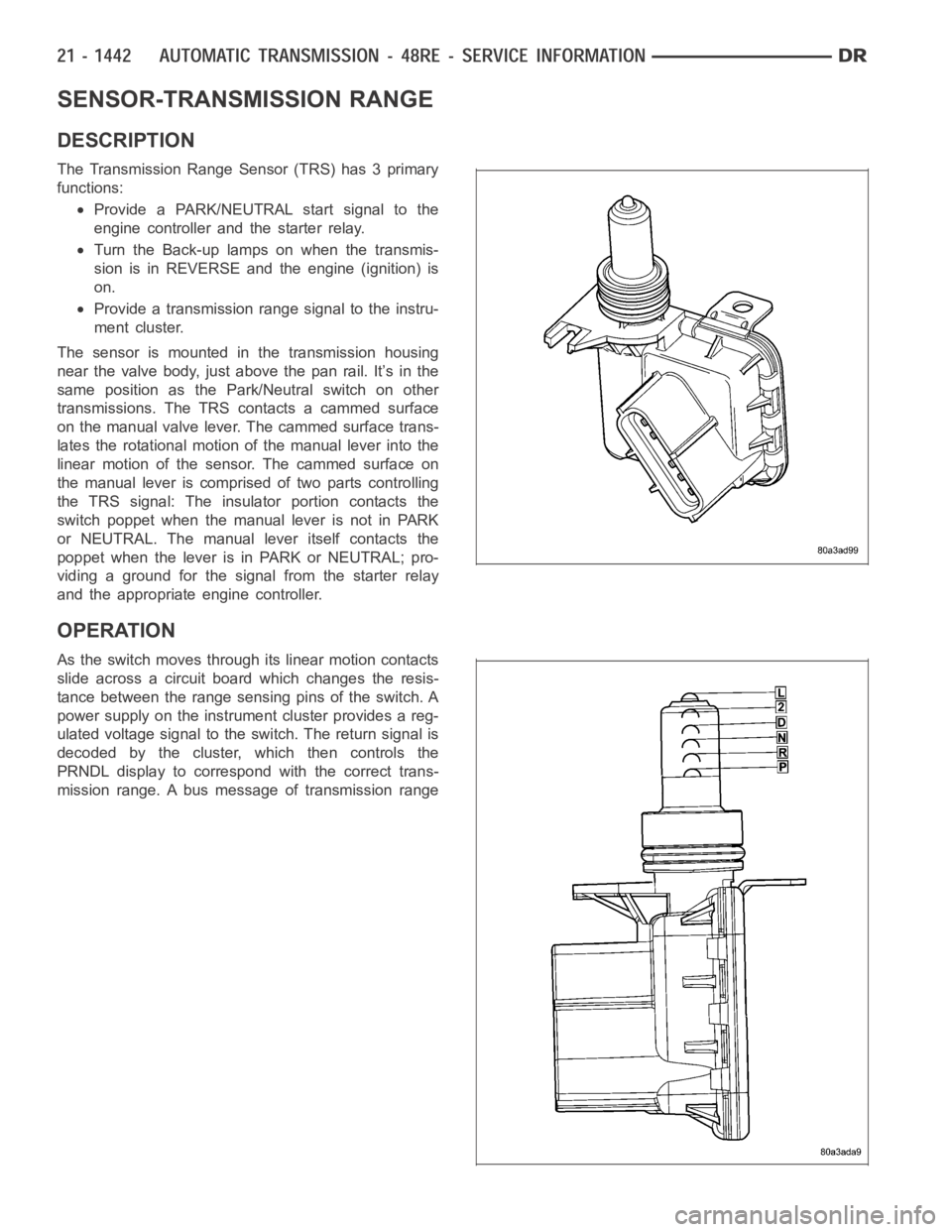
SENSOR-TRANSMISSION RANGE
DESCRIPTION
The Transmission Range Sensor (TRS) has 3 primary
functions:
Provide a PARK/NEUTRAL start signal to the
engine controller and the starter relay.
Turn the Back-up lamps on when the transmis-
sion is in REVERSE and the engine (ignition) is
on.
Provide a transmission range signal to the instru-
ment cluster.
The sensor is mounted in the transmission housing
near the valve body, just above the pan rail. It’s in the
same position as the Park/Neutral switch on other
transmissions. The TRS contacts a cammed surface
on the manual valve lever. The cammed surface trans-
lates the rotational motion of the manual lever into the
linear motion of the sensor. The cammed surface on
the manual lever is comprised of two parts controlling
the TRS signal: The insulator portion contacts the
switch poppet when the manual lever is not in PARK
or NEUTRAL. The manual lever itself contacts the
poppet when the lever is in PARK or NEUTRAL; pro-
viding a ground for the signal from the starter relay
and the appropriate engine controller.
OPERATION
As the switch moves through its linear motion contacts
slide across a circuit board which changes the resis-
tance between the range sensing pins of the switch. A
power supply on the instrument cluster provides a reg-
ulated voltage signal to the switch. The return signal is
decoded by the cluster, which then controls the
PRNDL display to correspond with the correct trans-
mission range. A bus message of transmission range