Page 1829 of 5267
18. Install a long bolt into front of camshaft to aid in
removal of the camshaft. Remove camshaft, being
careful not to damage cam bearings with the cam
lobes.
INSPECTION
1. The cam bearings are not serviceable. Do not attempt to replace cam bearings for any reason.
INSTALLATION
INSTALLATION - CAMSHAFT CORE HOLE PLUG
1. Clean core hole in block.
NOTE: Do not apply adhesive to the new core hole plug. A new plug will have adhesive pre-applied.
2. Install a new core hole plug at the rear of camshaft, using suitable flat faced tool. The plug must be fully seated
on the cylinder block shoulder.
Page 1832 of 5267
CAUTION: 5.7L engines equipped with MDS uses both standard roller tappetsand deactivating roller tap-
pets, for use with the Multi Displacement System. The deactivating rollertappets must be used in cylinders
1,4,6,7. The deactivating tappets can be identified by the two holes in theside of the tappet body, for the
latching pins.
8. Install tappets (2) and retaining yoke assembly (1). (Refer to 9 - ENGINE/ENGINE BLOCK/HYDRAULIC LIFT-
ERS (CAM IN BLOCK) - INSTALLATION).
9. Install both left and right cylinder heads (4) (Refer
to 9 - ENGINE/CYLINDER HEAD - INSTALLA-
TION).
10. Install pushrods.
Page 1836 of 5267
CRANKSHAFT
REMOVAL
1. Remove the vibration damper (1) (Refer to 9 -
ENGINE/ENGINE BLOCK/VIBRATION DAMPER -
REMOVAL).
2. Remove the rear oil seal retainer (Refer to 9 -
ENGINE/ENGINE BLOCK/CRANKSHAFT REAR
OIL SEAL RETAINE - REMOVAL).
3. Remove the oil pan (Refer to 9 - ENGINE/LUBRI-
CATION/OIL PAN - REMOVAL).
4. Remove the oil pump pickup.
5. Remove the windage tray/oil pan gasket.
Page 1839 of 5267
11. Remove main bearing caps (1) and bearings one
at a time.
12. Remove the thrust washers.
13. Remove the crankshaft out of the block.
Page 1840 of 5267
INSTALLATION
1. Select the proper main bearings (Refer to 9 -
ENGINE/ENGINE BLOCK/CRANKSHAFT MAIN
BEARINGS - STANDARD PROCEDURE).
2. Install main bearings in block and caps, and lubri-
cate bearings.
3. Position the crankshaft into the cylinder block.
4. Install the thrust washers (1).
Page 1842 of 5267
6.Step 1 – 27 Nꞏm ( 20 ft. lbs.) torque.
7.
Step 2 – Turn main cap bolts an additional 90°.
8. Install the crossbolts with new washer/gasket.
Starting with crossbolt A torque each crossbolt to
28 Nꞏm ( 21 ft. lbs.)torque.
9. Repeat crossbolt torque procedure.
10. Measure crankshaft end play (Refer to 9 -
ENGINE/ENGINE BLOCK/CRANKSHAFT MAIN
BEARINGS - STANDARD PROCEDURE).
11. Position the connecting rods onto the crankshaft and install the rod bearing caps (Refer to 9 - ENGINE/ENGINE
BLOCK/PISTON & CONNECTING ROD - INSTALLATION).
Page 1844 of 5267
14. Install the timing chain cover (1) (Refer to 9 - ENGINE/VALVE TIMING/TIMING BELT / CHAIN COVER(S) -
INSTALLATION).
15. Install the rear main seal and retainer (Refer to 9
- ENGINE/ENGINE BLOCK/CRANKSHAFT REAR
OIL SEAL RETAINE - INSTALLATION).
16. Install the windage tray/oil pan gasket.
17. Install the oil pick up tube.
18. Install the oil pan (Refer to 9 - ENGINE/LUBRICA-
TION/OIL PAN - INSTALLATION).
19. Install the vibration damper (Refer to 9 - ENGINE/
ENGINE BLOCK/VIBRATION DAMPER - INSTAL-
LATION).
20. Install the engine (Refer to 9 - ENGINE -
INSTALLATION).
Page 1845 of 5267

BEARINGS - CRANKSHAFT MAIN
STANDARD PROCEDURE - CRANKSHAFT MAIN BEARING - FITTING
MAIN BEARING JOURNAL DIAMETER (CRANKSHAFT REMOVED)
Crankshaft removed from the cylinder block.
Clean the oil off the main bearing journal.
Determine the maximum diameter of the journal with a micrometer. Measure at two locations 90° apart at each end
of the journal.
The maximum allowable taper is 0.008mm (0.0004 inch.) and maximum out of round is 0.005mm (0.0002 inch).
Compare the measured diameter with the journal diameter specification (Main Bearing Fitting Chart). Select inserts
required to obtain the specified bearing-to-journal clearance.
CRANKSHAFT MAIN BEARING SELECTION
The main bearings are “select fit” to achieve proper oil clearances. For main bearing selection, the crankshaft coun-
terweight has grade identification marks stamped into it. These marks areread from left to right, corresponding with
journalnumber1,2,3,4and5.
NOTE: Service main bearings are coded. These codes identify what size (grade) the bearing is.
MAIN BEARING SELECTION CHART - 5.7L
GRADE SIZE mm (in.) FOR USE WITH
MARKING JOURNAL SIZE
A0.008 mm U/S 64.988–64.995 mm
(0.0004 in.) U/S (2.5585– 2.5588in.)
BNOMINAL 64.996–65.004 mm
(2.5588–2.5592 in.)
C0.008 mm O/S 65.005–65.012 mm
(0.0004 in.) O/S (2.5592–2.5595 in.)
INSPECTION
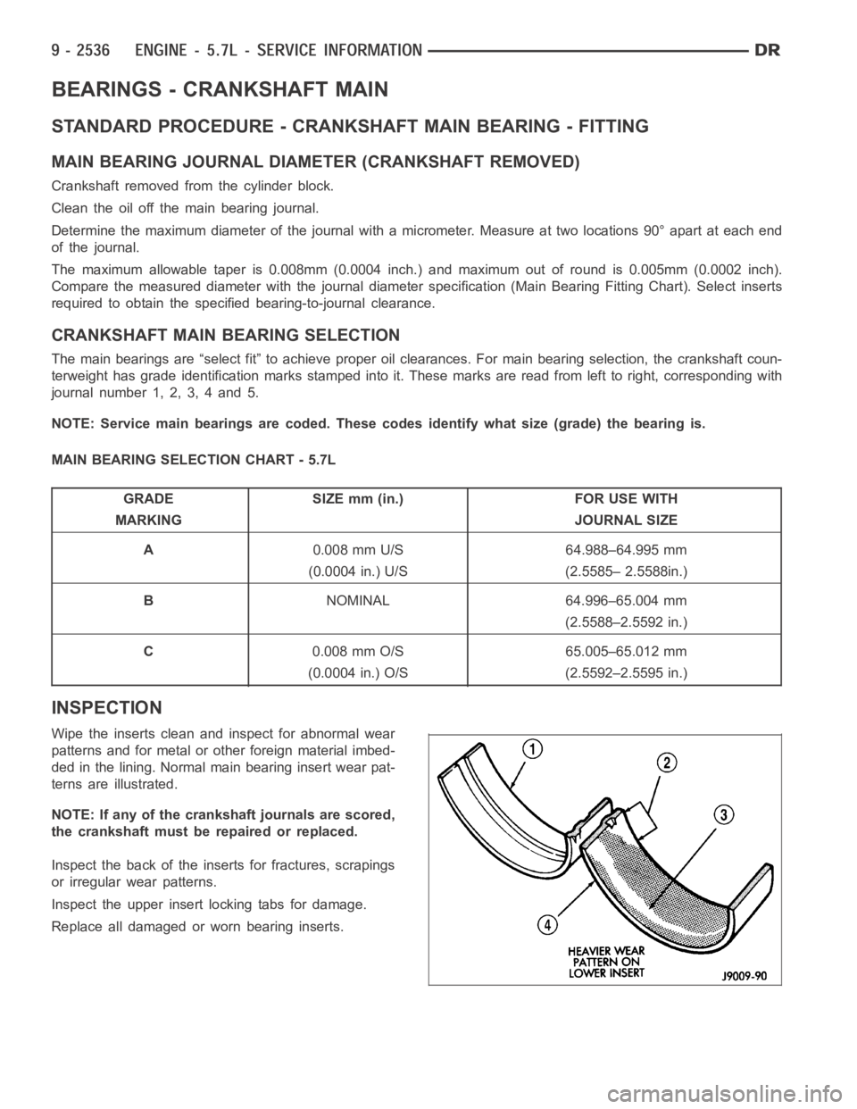
Wipe the inserts clean and inspect for abnormal wear
patterns and for metal or other foreign material imbed-
ded in the lining. Normal main bearing insert wear pat-
terns are illustrated.
NOTE: If any of the crankshaft journals are scored,
the crankshaft must be repaired or replaced.
Inspect the back of the inserts for fractures, scrapings
or irregular wear patterns.
Inspect the upper insert locking tabs for damage.
Replace all damaged or worn bearing inserts.