Page 1725 of 5267
FILTER - ENGINE OIL
REMOVAL
All engines are equipped with a high quality full-flow,
disposable type oil filter. DaimlerChrysler Corporation
recommends a Mopar
or equivalent oil filter be used.
1. Position a drain pan under the oil filter.
2. Using a suitable oil filter wrench loosen filter.
3. Rotate the oil filter counterclockwise to remove it
from the cylinder block oil filter boss.
4. When filter separates from cylinder block oil filter
boss, tip gasket end upward to minimize oil spill.
Remove filter from vehicle.
NOTE: Make sure filter gasket was removed with
filter.
5. With a wiping cloth, clean the gasket sealing sur-
face of oil and grime.
INSTALLATION
1. Lightly lubricate oil filter gasket (2) with engine oil.
2. Thread filter (3) onto adapter nipple. When gasket
makes contact with sealing surface, hand tighten
filter one full turn, do not over tighten.
3. Add oil, verify crankcase oil level and start engine.
Inspect for oil leaks.
Page 1733 of 5267
15. Remove the heater hoses (1) from the engine
front cover and the heater core.
16. Unclip (2) and remove heater hoses and tubes
from intake manifold.
17. Remove coolant temperature sensor (Refer to 7 -
COOLING/ENGINE/ENGINE COOLANT TEM-
PERATURE SENSO - REMOVAL).
18. Remove intake manifoldretaining fasteners in
reverse order of tightening sequence.
19. Remove intake manifold.
CLEANING
NOTE: There is NO approved repair procedure for the intake manifold. If severe damage is found during
inspection, the intake manifold must be replaced.
Before installing the intake manifoldthoroughly clean the mating surfaces. Use a suitable cleaning solvent, then air
dry.
INSPECTION
1. Inspect the intake sealing surface for cracks, nicks and distortion.
2. Inspect the intake manifold vacuum hose fittings for looseness or blockage.
3. Inspect the manifold to throttlebody mating surface for cracks, nicks and distortion.
Page 1739 of 5267

VALVE TIMING
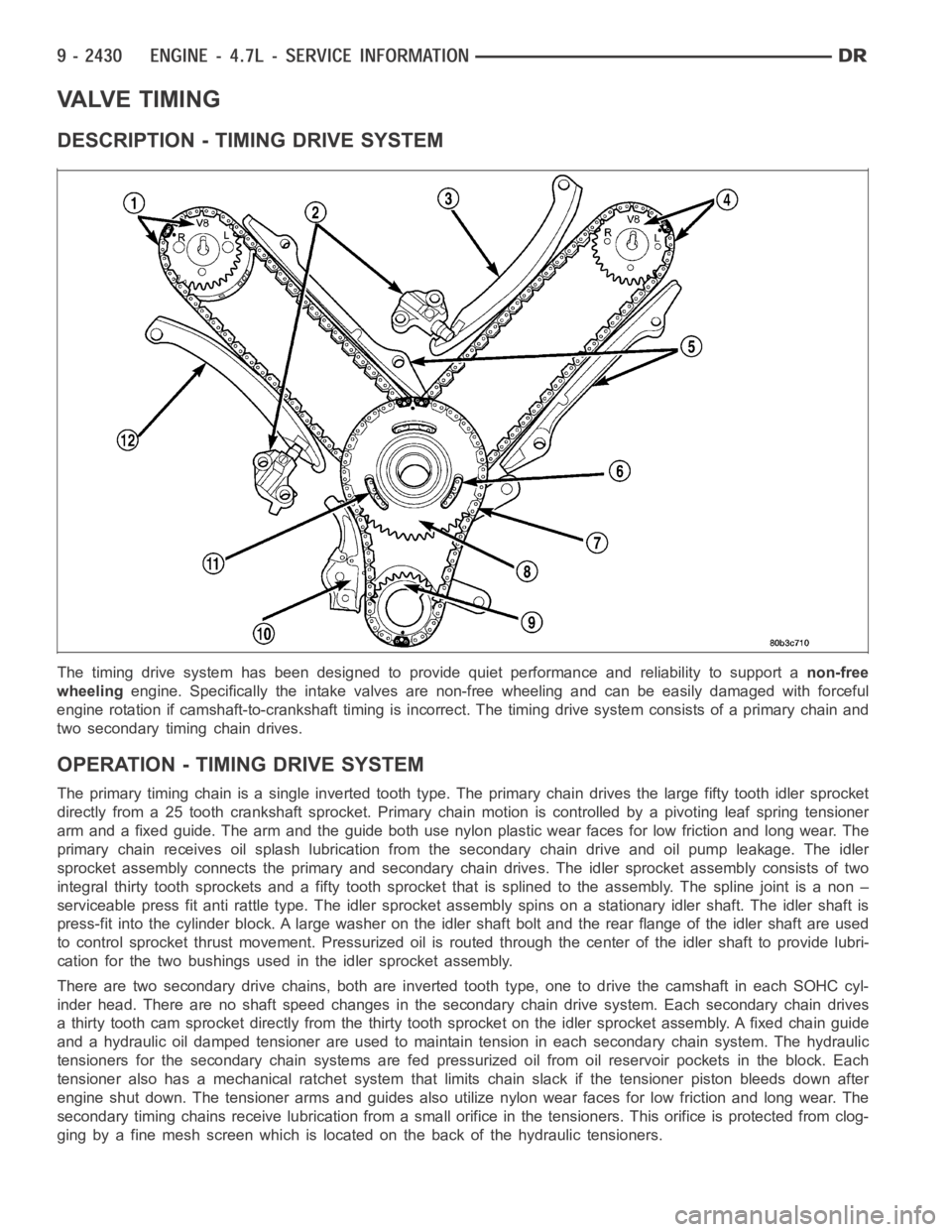
DESCRIPTION - TIMING DRIVE SYSTEM
The timing drive system has been designed to provide quiet performance andreliability to support anon-free
wheelingengine. Specifically the intake valves are non-free wheeling and can be easily damaged with forceful
engine rotation if camshaft-to-crankshaft timing is incorrect. The timing drive system consists of a primary chain and
two secondary timing chain drives.
OPERATION - TIMING DRIVE SYSTEM
The primary timing chain is a single inverted tooth type. The primary chaindrives the large fifty tooth idler sprocket
directly from a 25 tooth crankshaft sprocket. Primary chain motion is controlled by a pivoting leaf spring tensioner
arm and a fixed guide. The arm and the guide both use nylon plastic wear facesfor low friction and long wear. The
primary chain receives oil splash lubrication from the secondary chain drive and oil pump leakage. The idler
sprocket assembly connects the primary and secondary chain drives. The idler sprocket assembly consists of two
integral thirty tooth sprockets and afifty tooth sprocket that is splinedto the assembly. The spline joint is a non –
serviceable press fit anti rattle type. The idler sprocket assembly spinson a stationary idler shaft. The idler shaft is
press-fit into the cylinder block. A large washer on the idler shaft bolt and the rear flange of the idler shaft are used
to control sprocket thrust movement. Pressurized oil is routed through the center of the idler shaft to provide lubri-
cation for the two bushings used in the idler sprocket assembly.
There are two secondary drive chains, both are inverted tooth type, one to drive the camshaft in each SOHC cyl-
inder head. There are no shaft speed changes in the secondary chain drive system. Each secondary chain drives
a thirty tooth cam sprocket directly from the thirty tooth sprocket on the idler sprocket assembly. A fixed chain guide
and a hydraulic oil damped tensioner are used to maintain tension in each secondary chain system. The hydraulic
tensioners for the secondary chainsystems are fed pressurized oil from oil reservoir pockets in the block. Each
tensioner also has a mechanical ratchet system that limits chain slack if the tensioner piston bleeds down after
engine shut down. The tensioner arms and guides also utilize nylon wear faces for low friction and long wear. The
secondary timing chains receive lubrication from a small orifice in the tensioners. This orifice is protected from clog-
ging by a fine mesh screen which is located on the back of the hydraulic tensioners.
Page 1740 of 5267

STANDARD PROCEDURE
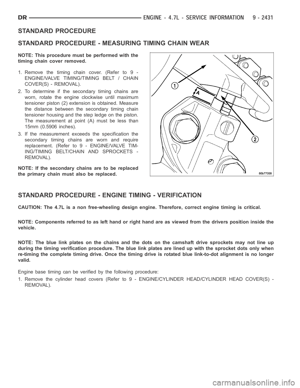
STANDARD PROCEDURE - MEASURING TIMING CHAIN WEAR
NOTE: This procedure must be performed with the
timing chain cover removed.
1.Removethetimingchaincover.(Referto9-
ENGINE/VALVE TIMING/TIMING BELT / CHAIN
COVER(S) - REMOVAL).
2. To determine if the secondary timing chains are
worn, rotate the engine clockwise until maximum
tensioner piston (2) extension is obtained. Measure
the distance between the secondary timing chain
tensioner housing and the step ledge on the piston.
The measurement at point (A) must be less than
15mm (0.5906 inches).
3. If the measurement exceeds the specification the
secondary timing chains are worn and require
replacement. (Refer to 9 - ENGINE/VALVE TIM-
ING/TIMING BELT/CHAIN AND SPROCKETS -
REMOVAL).
NOTE: If the secondary chains are to be replaced
the primary chain must also be replaced.
STANDARD PROCEDURE - ENGINE TIMING - VERIFICATION
CAUTION: The 4.7L is a non free-wheeling design engine. Therefore, correct engine timing is critical.
NOTE: Components referred to as left hand or right hand are as viewed from thedriverspositioninsidethe
vehicle.
NOTE: The blue link plates on the chains and the dots on the camshaft drive sprockets may not line up
during the timing verification procedure. The blue link plates are lined up with the sprocket dots only when
re-timing the complete timing drive.Once the timing drive is rotated bluelink-to-dot alignment is no longer
valid.
Engine base timing can be verified by the following procedure:
1. Remove the cylinder head covers (Refer to 9 - ENGINE/CYLINDER HEAD/CYLINDERHEADCOVER(S)-
REMOVAL).
Page 1741 of 5267

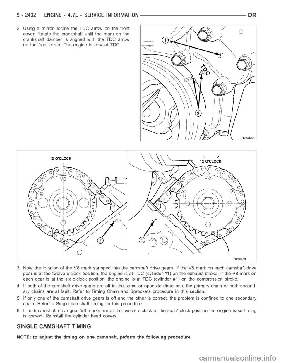
2. Using a mirror, locate the TDC arrow on the front
cover. Rotate the crankshaft until the mark on the
crankshaft damper is aligned with the TDC arrow
on the front cover. The engine is now at TDC.
3. Note the location of the V8 mark stamped into the camshaft drive gears. IftheV8markoneachcamshaftdrive
gear is at the twelve o’clock position, the engine is at TDC (cylinder #1) onthe exhaust stroke. If the V8 mark on
each gear is at the six o’clock position, the engine is at TDC (cylinder #1) on the compression stroke.
4. If both of the camshaft drive gears are off in the same or opposite directions, the primary chain or both second-
ary chains are at fault. Refer to Timing Chain and Sprockets procedure in this section.
5. If only one of the camshaft drive gears is off and the other is correct, theproblem is confined to one secondary
chain. Refer to Single camshaft timing, in this procedure.
6. If both camshaft drive gear V8 marks are at the twelve o’clock or the six o’clock position the engine base timing
is correct. Reinstall the cylinder head covers.
SINGLE CAMSHAFT TIMING
NOTE: to adjust the timing on one camshaft, peform the following procedure.
Page 1745 of 5267
COVER - TIMING
REMOVAL
1. Disconnect the battery negative cable.
2. Drain cooling system (Refer to 7 - COOLING -
STANDARD PROCEDURE).
3. Disconnect both heater hoses at timing cover.
4. Disconnect lower radiator hose at engine.
5. Remove crankshaft damper (Refer to 9 - ENGINE/
ENGINE BLOCK/VIBRATION DAMPER -
REMOVAL).
6. Remove accessory drive belt tensioner assembly
(1).
7. Remove the generator and A/C compressor.
CAUTION:The4.7LengineusesanRTVsealer
instead of a gasket to seal the front cover to the
engine block, from the factory. For service, Mopar
Grey Engine RTV sealant must be substituted.
NOTE: It is not necessary to remove the water
pump for timing cover removal.
8. Remove the bolts holding the timing cover to
engine block.
9. Remove cover.
Page 1746 of 5267

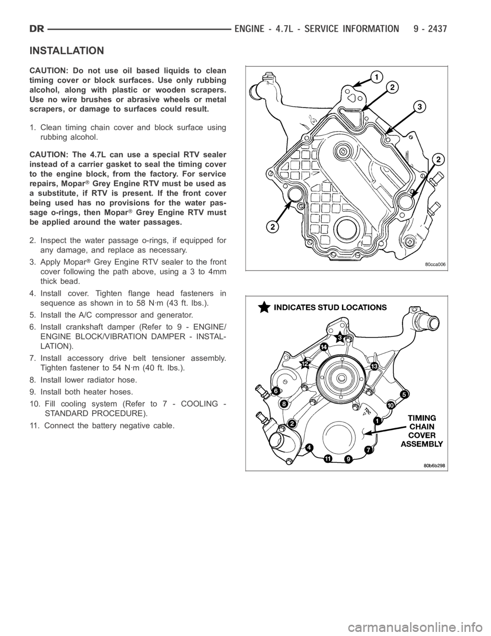
INSTALLATION
CAUTION: Do not use oil based liquids to clean
timing cover or block surfaces. Use only rubbing
alcohol, along with plastic or wooden scrapers.
Use no wire brushes or abrasive wheels or metal
scrapers, or damage to surfaces could result.
1. Clean timing chain cover and block surface using
rubbing alcohol.
CAUTION: The 4.7L can use a special RTV sealer
instead of a carrier gasket to seal the timing cover
to the engine block, from the factory. For service
repairs, Mopar
Grey Engine RTV must be used as
a substitute, if RTV is present. If the front cover
being used has no provisions for the water pas-
sage o-rings, then Mopar
Grey Engine RTV must
be applied around the water passages.
2. Inspect the water passage o-rings, if equipped for
any damage, and replace as necessary.
3. Apply Mopar
Grey Engine RTV sealer to the front
cover following the path above, using a 3 to 4mm
thick bead.
4. Install cover. Tighten flange head fasteners in
sequence as shown in to 58 Nꞏm (43 ft. lbs.).
5. Install the A/C compressor and generator.
6. Install crankshaft damper (Refer to 9 - ENGINE/
ENGINE BLOCK/VIBRATION DAMPER - INSTAL-
LATION).
7. Install accessory drive belt tensioner assembly.
Tighten fastener to 54 Nꞏm (40 ft. lbs.).
8. Install lower radiator hose.
9. Install both heater hoses.
10. Fill cooling system (Refer to 7 - COOLING -
STANDARD PROCEDURE).
11. Connect the battery negative cable.
Page 1747 of 5267
TIMING CHAIN & SPROCKETS
REMOVAL
1. Disconnect negative cable from battery.
2. Drain cooling system (Refer to 7 - COOLING -
STANDARD PROCEDURE).
3. Remove right and left cylinder head covers (Refer
to 9 - ENGINE/CYLINDER HEAD/CYLINDER
HEAD COVER(S) - REMOVAL).
4. Remove radiator fan shroud.
5. Rotate engine until timing mark (2) on crankshaft
damper aligns with TDC mark on timing chain
cover (2) (#1 cylinder exhaust stroke) and the cam-
shaft sprocket “V8” marks are at the 12 o’clock
position (1,2).