Page 1793 of 5267
13. Remove the head bolts from each cylinder head,
using the sequence provided, and remove cylin-
der heads. Discard the cylinder head gasket.
CLEANING
Clean all surfaces of cylinder block and cylinder heads.
Clean cylinder block front and rear gasket surfaces using a suitable solvent.
INSPECTION
1. Inspect the cylinder head for out-of-flatness, using a straightedge and a feeler gauge. If tolerances exceed
0.0508 mm (0.002 in.) replace the cylinder head.
2. Inspect the valve seats for damage. Service the valve seats as necessary.
3. Inspect the valve guides for wear, cracks or looseness. If either condition exist, replace the cylinder head.
4. Inspect pushrods. Replace worn or bent pushrods.
Page 1794 of 5267
INSTALLATION
1. Clean all surfaces of cylinder block and cylinder heads.
2. Clean cylinder block front and rear gasket surfaces using a suitable solvent.
CAUTION: The head gaskets (1) are not interchangeable between left and right sides. They are marked “L”
and “R” to indicate left and right sides.
CAUTION: The head gaskets (1) are marked “TOP” to indicate which side goes up.
Page 1795 of 5267
3. Position new cylinder head gaskets (5) onto the
cylinder block.
4. Position cylinder heads (4) onto head gaskets (5)
and cylinder block.
Page 1805 of 5267

VALVES & SEATS - INTAKE/EXHAUST
DESCRIPTION
DESCRIPTION - VALVE GUIDES
The valve guides are made of powdered metal and are pressed into the cylinder head. The guides are not replace-
able or serviceable, and valve guide reaming is not recommended. If the guides are worn beyond acceptable limits,
replace the cylinder heads.
DESCRIPTION
Both the intake and exhaust valves are made of steel. The intake valve is 50.93 mm (2.00 inches) in diameter and
the exhaust valve is 39.53 mm (1.55 inches) in diameter. All valves use three bead lock keepers to retain the
springs and promote valve rotation.
STANDARD PROCEDURE - REFACING
NOTE: Valve seats that are worn or burned can be reworked, provided that correct angle and seat width are
maintained. Otherwise the cylinder head must be replaced.
NOTE: When refacing valves and valve seats, it is important that the correct size valve guide pilot be used
for reseating stones. A true and complete surface must be obtained.
1. Using a suitable dial indicator measure the center of the valve seat Total run out must not exceed 0.051 mm
(0.002 in).
2. Apply a small amount of Prussian blue to the valve seat, insert the valve into the cylinder head, while applying
light pressure on the valve rotate the valve. Remove the valve and examine the valve face. If the blue is trans-
ferred below the top edge of the valve face, lower the valve seat using a 15 degree stone. If the blue is trans-
ferred to the bottom edge of the valve face, raise the valve seat using a 65 degree stone.
3. When the seat is properly positioned the width of the intake seat must be 1.018 - 1.62 mm (0.0464 - 0.0637 in.)
and the exhaust seat must be 1.48 - 1.92 mm (0.058 - 0.075 in.).
4. Check the valve spring installed height after refacing the valve and seat.Theinstalledheightforbothintakeand
exhaust valve springs must not exceed 46.0 mm (1.81 in.).
VALVE FACE AND VALVE SEAT ANGLE CHART
DESCRIPTION SPECIFICATION
SEAT WIDTH
INTAKE 1.018 - 1.62 mm
(0.0464 - 0.0637 in.)
EXHAUST 1.48 - 1.92 mm
(0.058 - 0.075 in.)
FA C E A N G L E
(INT. AND EXT.) 45° - 45
1⁄2°
SEAT ANGLE
(INT. AND EXT.) 44
1⁄2° - 45°
Page 1806 of 5267

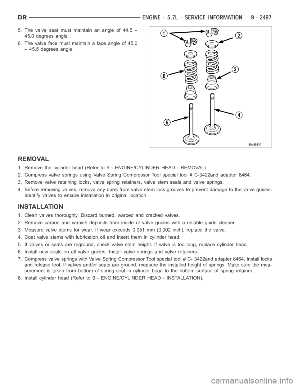
5. The valve seat must maintain an angle of 44.5 –
45.0 degrees angle.
6. Thevalvefacemustmaintainafaceangleof45.0
– 45.5 degrees angle.
REMOVAL
1. Remove the cylinder head (Refer to 9 - ENGINE/CYLINDER HEAD - REMOVAL).
2. Compress valve springs using Valve Spring Compressor Tool special tool# C-3422and adapter 8464.
3. Remove valve retaining locks, valve spring retainers, valve stem sealsand valve springs.
4. Before removing valves, remove any burrs from valve stem lock grooves toprevent damage to the valve guides.
Identify valves to ensure installation in original location.
INSTALLATION
1. Clean valves thoroughly. Discard burned, warped and cracked valves.
2. Remove carbon and varnish deposits from inside of valve guides with a reliable guide cleaner.
3. Measure valve stems for wear. If wear exceeds 0.051 mm (0.002 inch), replace the valve.
4. Coat valve stems with lubrication oil and insert them in cylinder head.
5. If valves or seats are reground, check valve stem height. If valve is too long, replace cylinder head.
6. Install new seals on all valve guides. Install valve springs and valve retainers.
7. Compress valve springs with Valve Spring Compressor Tool special tool #C- 3422and adapter 8464, install locks
and release tool. If valves and/or seats are ground, measure the installedheight of springs. Make sure the mea-
surement is taken from bottom of spring seat in cylinder head to the bottom surface of spring retainer.
8. Install cylinder head (Refer to 9 - ENGINE/CYLINDER HEAD - INSTALLATION).
Page 1818 of 5267
10. Install spring compressor (1,3,), special tool#
9065, and exhaust adapter arm (1) tool # 9065if
needed.
NOTE: All valve springs and seals are removed in
the same manner.
11. Insert air hose (1) into spark plug hole and charge cylinder with air.
NOTE: Tap the top of the valve spring retainer to loosen the spring retainers locks.
12. Compress valve spring with valve spring compessor (3) tool # 9065and remove valve retainer locks.
13. Release spring compressor (3) and remove valve spring.
NOTE: The valve springs are interchangeable between intake and exhaust.
14. Remove valve seal.
Page 1820 of 5267
1. Install valve seal.
2. Install valve spring.
3. Using special tool# 9065 (1,3,), compress valve
spring and install valve spring retainer and locks.
4. Release air charge in cylinder (1).
5. Remove spring compressor tool # 9065 (3).
CAUTION: Verify that the pushrods are fully seated into lifter and rocker arm. Recheck after rocker arm
shaft has been torqued to specification.
Page 1824 of 5267

ENGINE BLOCK
CLEANING
Thoroughly clean the oil pan and engine block gasket surfaces.
Use compressed air to clean out:
The galley at the oil filter adaptor hole.
The front and rear oil galley holes.
The feed holes for the crankshaft main bearings.
Once the block has been completely cleaned, apply Loctite PST pipe sealantwith Teflon 592 to the threads of the
front and rear oil galley plugs. Tighten the 1/4 inch NPT plugs to 20 Nꞏm (177in. lbs.) torque. Tighten the 3/8 inch
NPT plugs to 27 Nꞏm (240 in. lbs.) torque.
INSPECTION
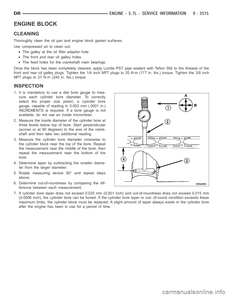
1. It is mandatory to use a dial bore gauge to mea-
sure each cylinder bore diameter. To correctly
select the proper size piston, a cylinder bore
gauge, capable of reading in 0.003 mm (.0001 in.)
INCREMENTS is required. If a bore gauge is not
available, do not use an inside micrometer.
2. Measure the inside diameter of the cylinder bore at
three levels below top of bore. Start perpendicular
(across or at 90 degrees) to the axis of the crank-
shaft and then take two additional reading.
3. Measure the cylinder bore diameter crosswise to
the cylinder block near the top of the bore. Repeat
the measurement near the middle of the bore, then
repeat the measurement near the bottom of the
bore.
4. Determine taper by subtracting the smaller diame-
ter from the larger diameter.
5. Rotate measuring device 90° and repeat steps
above.
6. Determine out-of-roundness by comparing the dif-
ference between each measurement.
7. If cylinder bore taper does not exceed 0.025 mm (0.001 inch) and out-of-roundness does not exceed 0.015 mm
(0.0006 inch), the cylinder bore can be honed. If the cylinder bore taper orout- of-round condition exceeds these
maximum limits, the cylinder block must be replaced. A slight amount of taper always exists in the cylinder bore
after the engine has been in use for a period of time.