2006 DODGE RAM SRT-10 engine
[x] Cancel search: enginePage 5075 of 5267
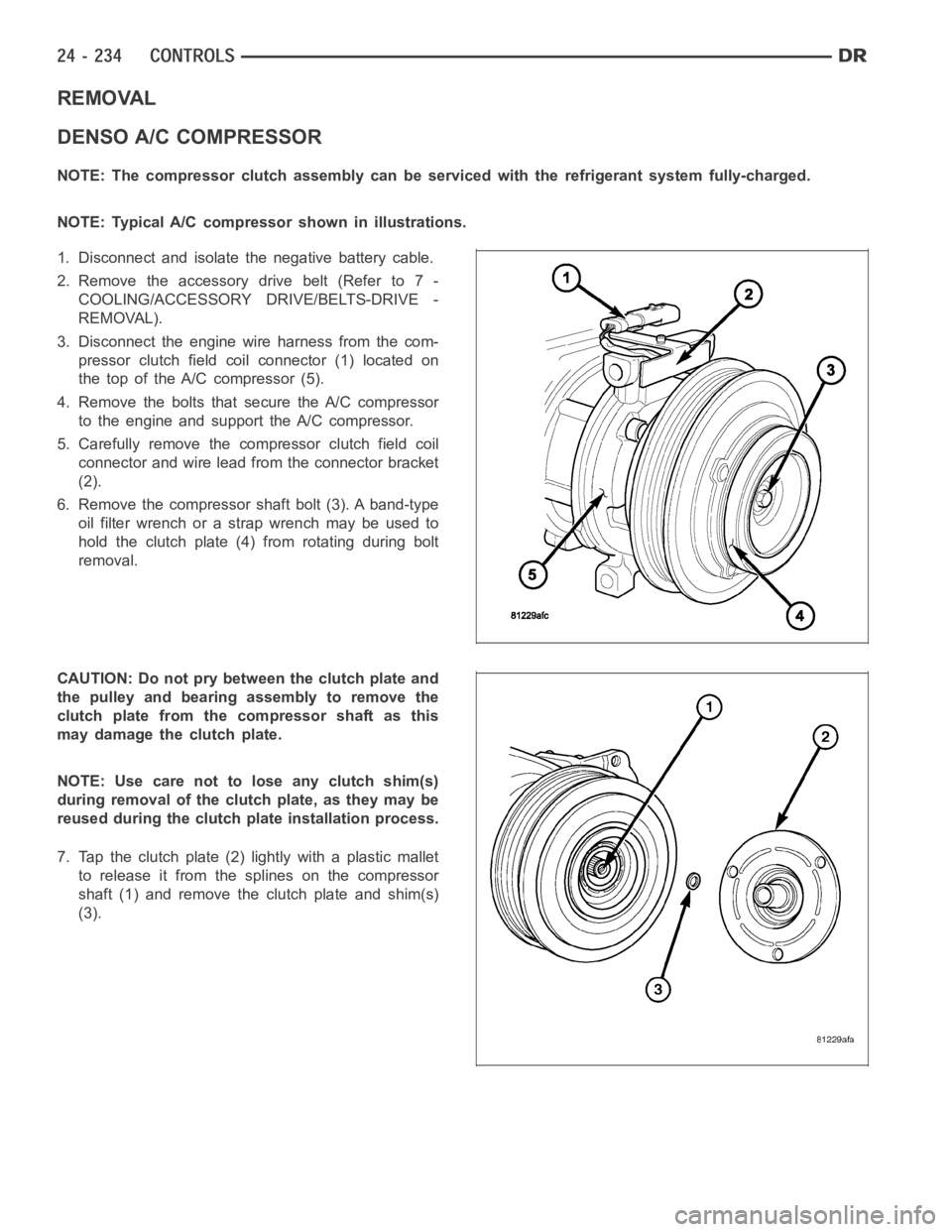
REMOVAL
DENSO A/C COMPRESSOR
NOTE: The compressor clutch assembly can be serviced with the refrigerantsystem fully-charged.
NOTE: Typical A/C compressor shown in illustrations.
1. Disconnect and isolate the negative battery cable.
2. Remove the accessory drive belt (Refer to 7 -
COOLING/ACCESSORY DRIVE/BELTS-DRIVE -
REMOVAL).
3. Disconnect the engine wire harness from the com-
pressor clutch field coilconnector (1) located on
the top of the A/C compressor (5).
4. Remove the bolts that secure the A/C compressor
to the engine and support the A/C compressor.
5. Carefully remove the compressor clutch field coil
connector and wire lead from the connector bracket
(2).
6. Remove the compressor shaft bolt (3). A band-type
oil filter wrench or a strap wrench may be used to
hold the clutch plate (4) from rotating during bolt
removal.
CAUTION: Do not pry between the clutch plate and
the pulley and bearing assembly to remove the
clutch plate from the compressor shaft as this
may damage the clutch plate.
NOTE: Use care not to lose any clutch shim(s)
during removal of the clutch plate, as they may be
reused during the clutch plate installation process.
7. Tap the clutch plate (2) lightly with a plastic mallet
to release it from the splines on the compressor
shaft (1) and remove the clutch plate and shim(s)
(3).
Page 5077 of 5267
1. Disconnect and isolate negative battery cable.
2. Remove the accessory drive belt (Refer to 7 -
COOLING/ACCESSORY DRIVE/BELTS-DRIVE -
REMOVAL).
3. Raise and support the vehicle.
4. Disconnect the engine wire harness from the clutch
field coil connector (4).
5. Remove the bolts that secure the A/C compressor
(5)tothemountingbracket(Referto24-HEAT-
ING & AIR CONDITIONING/PLUMBING/COM-
PRESSOR-A/C - REMOVAL).
6. Remove the A/C compressor from the mounting
bracket and support the compressor while servicing
the clutch.
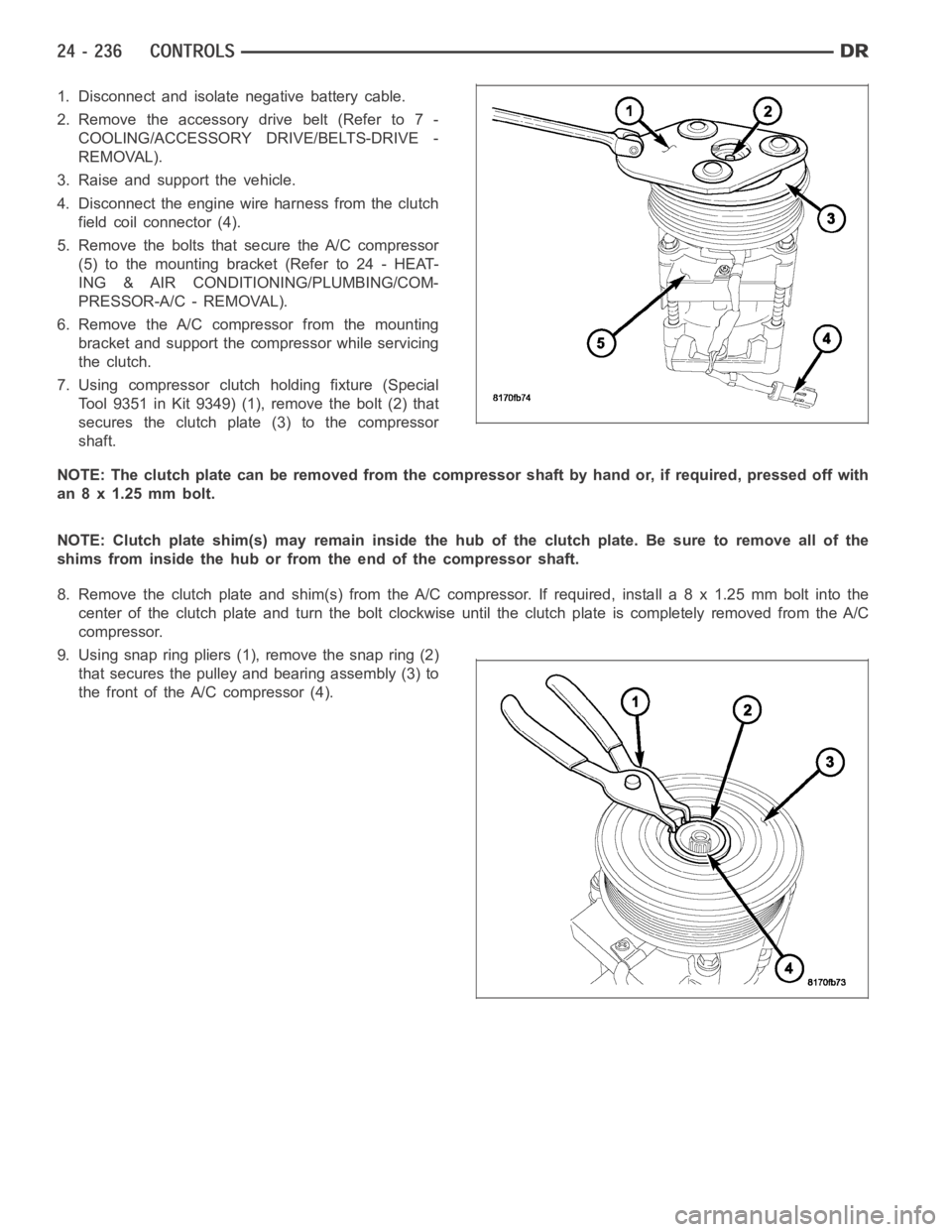
7. Using compressor clutch holding fixture (Special
Tool 9351 in Kit 9349) (1), remove the bolt (2) that
secures the clutch plate (3) to the compressor
shaft.
NOTE: The clutch plate can be removed from the compressor shaft by hand or, if required, pressed off with
an 8 x 1.25 mm bolt.
NOTE: Clutch plate shim(s) may remain inside the hub of the clutch plate. Besure to remove all of the
shims from inside the hub or from the end of the compressor shaft.
8. Remove the clutch plate and shim(s) from the A/C compressor. If required, install a 8 x 1.25 mm bolt into the
centeroftheclutchplateandturntheboltclockwiseuntiltheclutchplate is completely removed from the A/C
compressor.
9. Using snap ring pliers (1), remove the snap ring (2)
that secures the pulley and bearing assembly (3) to
the front of the A/C compressor (4).
Page 5081 of 5267
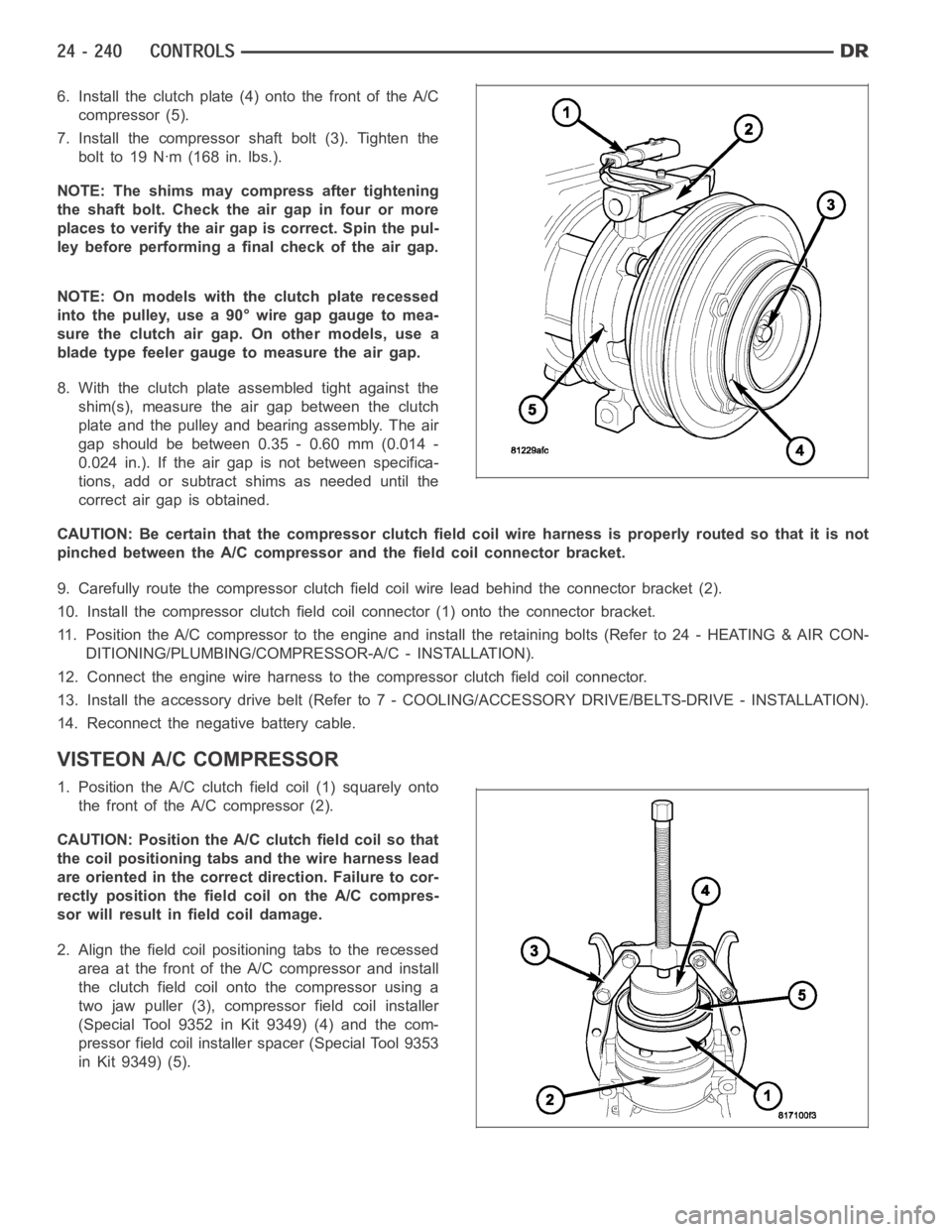
6. Install the clutch plate (4) onto the front of the A/C
compressor (5).
7. Install the compressor shaft bolt (3). Tighten the
bolt to 19 Nꞏm (168 in. lbs.).
NOTE: The shims may compress after tightening
the shaft bolt. Check the air gap in four or more
places to verify the air gap is correct. Spin the pul-
ley before performing a final check of the air gap.
NOTE: On models with the clutch plate recessed
intothepulley,usea90°wiregapgaugetomea-
sure the clutch air gap. On other models, use a
blade type feeler gauge to measure the air gap.
8. With the clutch plate assembled tight against the
shim(s), measure the air gap between the clutch
plate and the pulley and bearing assembly. The air
gap should be between 0.35 - 0.60 mm (0.014 -
0.024 in.). If the air gap is not between specifica-
tions, add or subtract shims as needed until the
correct air gap is obtained.
CAUTION: Be certain that the compressor clutch field coil wire harness is properly routed so that it is not
pinched between the A/C compressor and the field coil connector bracket.
9. Carefully route the compressor clutch field coil wire lead behind the connector bracket (2).
10. Install the compressor clutch fieldcoil connector (1) onto the connector bracket.
11. Position the A/C compressor to the engine and install the retaining bolts (Refer to 24 - HEATING & AIR CON-
DITIONING/PLUMBING/COMPRESSOR-A/C - INSTALLATION).
12. Connect the engine wire harness to the compressor clutch field coil connector.
13. Install the accessory drive belt (Refer to 7 - COOLING/ACCESSORY DRIVE/BELTS-DRIVE - INSTALLATION).
14. Reconnect the negative battery cable.
VISTEON A/C COMPRESSOR
1. Position the A/C clutch field coil (1) squarely onto
the front of the A/C compressor (2).
CAUTION: Position the A/C clutch field coil so that
the coil positioning tabs and the wire harness lead
are oriented in the correct direction. Failure to cor-
rectly position the fieldcoil on the A/C compres-
sor will result in field coil damage.
2. Align the field coil positioning tabs to the recessed
area at the front of the A/C compressor and install
the clutch field coil onto the compressor using a
two jaw puller (3), compressor field coil installer
(Special Tool 9352 in Kit 9349) (4) and the com-
pressor field coil installer spacer (Special Tool 9353
in Kit 9349) (5).
Page 5083 of 5267
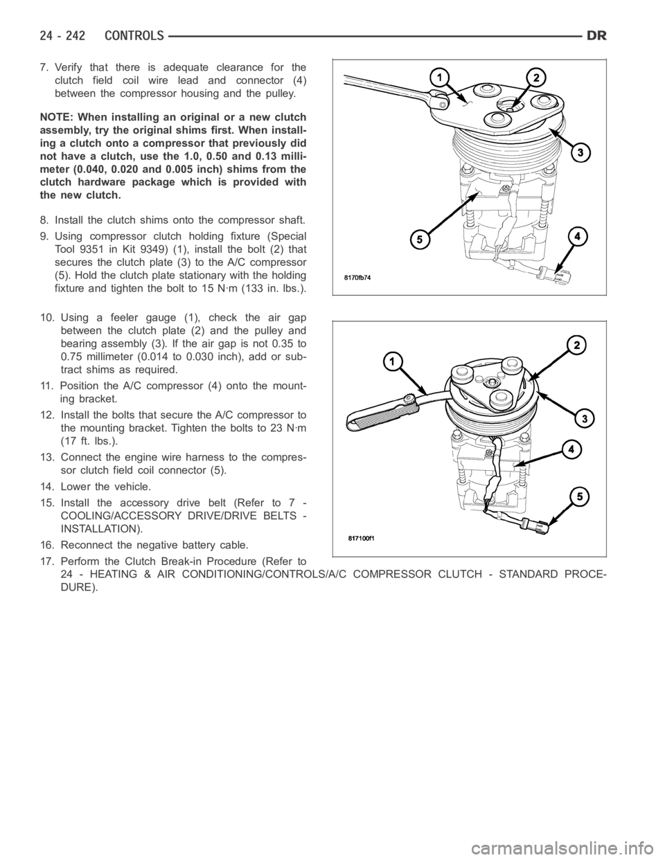
7. Verify that there is adequate clearance for the
clutch field coil wire lead and connector (4)
between the compressor housing and the pulley.
NOTE: When installing an original or a new clutch
assembly, try the original shims first. When install-
ing a clutch onto a compressor that previously did
not have a clutch, use the 1.0, 0.50 and 0.13 milli-
meter (0.040, 0.020 and 0.005 inch) shims from the
clutch hardware package which is provided with
the new clutch.
8. Install the clutch shims onto the compressor shaft.
9. Using compressor clutch holding fixture (Special
Tool 9351 in Kit 9349) (1), install the bolt (2) that
secures the clutch plate (3) to the A/C compressor
(5). Hold the clutch plate stationary with the holding
fixture and tighten the bolt to 15 Nꞏm (133 in. lbs.).
10. Using a feeler gauge (1), check the air gap
between the clutch plate (2) and the pulley and
bearing assembly (3). If the air gap is not 0.35 to
0.75 millimeter (0.014 to 0.030 inch), add or sub-
tract shims as required.
11. Position the A/C compressor (4) onto the mount-
ing bracket.
12. Install the bolts that secure the A/C compressor to
themountingbracket.Tightentheboltsto23Nꞏm
(17 ft. lbs.).
13. Connect the engine wire harness to the compres-
sor clutch field coil connector (5).
14. Lower the vehicle.
15. Install the accessory drive belt (Refer to 7 -
COOLING/ACCESSORY DRIVE/DRIVE BELTS -
INSTALLATION).
16. Reconnect the negative battery cable.
17. Perform the Clutch Break-in Procedure (Refer to
24 - HEATING & AIR CONDITIONING/CONTROLS/A/C COMPRESSOR CLUTCH - STANDARD PROCE-
DURE).
Page 5089 of 5267
SENSOR-EVAPORATOR TEMPERATURE
DESCRIPTION
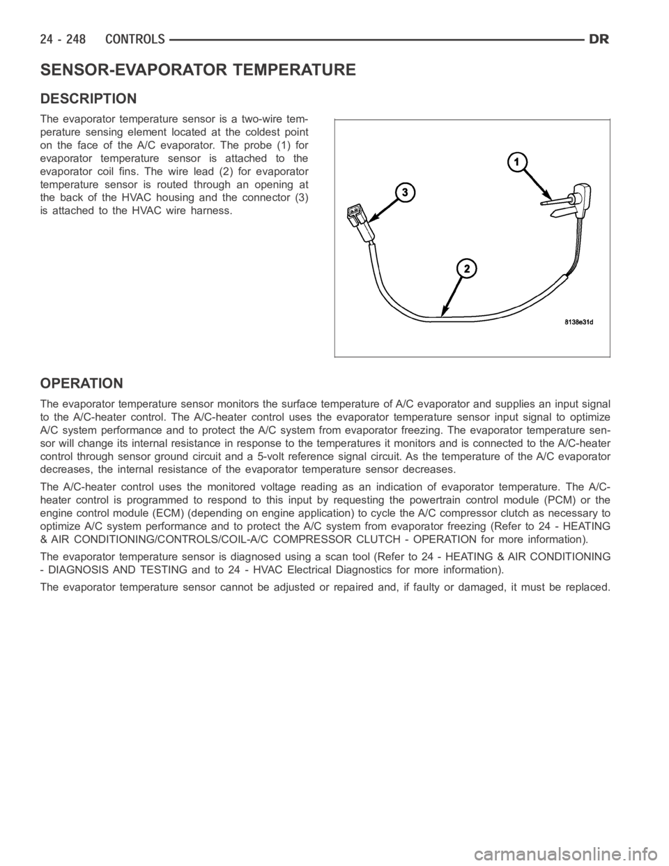
The evaporator temperature sensor is a two-wire tem-
perature sensing element located at the coldest point
on the face of the A/C evaporator. The probe (1) for
evaporator temperature sensor is attached to the
evaporator coil fins. The wire lead (2) for evaporator
temperature sensor is routed through an opening at
the back of the HVAC housing and the connector (3)
is attached to the HVAC wire harness.
OPERATION
The evaporator temperature sensor monitors the surface temperature of A/C evaporator and supplies an input signal
to the A/C-heater control. The A/C-heater control uses the evaporator temperature sensor input signal to optimize
A/C system performance and to protect the A/C system from evaporator freezing. The evaporator temperature sen-
sor will change its internal resistance in response to the temperatures itmonitors and is connected to the A/C-heater
control through sensor ground circuit and a 5-volt reference signal circuit. As the temperature of the A/C evaporator
decreases, the internal resistance of the evaporator temperature sensordecreases.
The A/C-heater control uses the monitored voltage reading as an indication of evaporator temperature. The A/C-
heater control is programmed to respond to this input by requesting the powertrain control module (PCM) or the
engine control module (ECM) (depending on engine application) to cycle the A/C compressor clutch as necessary to
optimize A/C system performance and to protect the A/C system from evaporatorfreezing(Referto24-HEATING
& AIR CONDITIONING/CONTROLS/COIL-A/C COMPRESSOR CLUTCH - OPERATION formore information).
The evaporator temperature sensor is diagnosed using a scan tool (Refer to24 - HEATING & AIR CONDITIONING
- DIAGNOSIS AND TESTING and to 24 - HVAC Electrical Diagnostics for more information).
The evaporator temperature sensor cannot be adjusted or repaired and, if faulty or damaged, it must be replaced.
Page 5092 of 5267

TRANSDUCER-A/C PRESSURE
DESCRIPTION
The A/C pressure transducer (1) is a switch that is
installed on a fitting located on the A/C discharge line.
An internally threaded fitting on the A/C pressure
transducer connects it to the externally threaded
Schrader-type fitting on the A/C discharge line. A rub-
ber O-ring seals the connection between the A/C pres-
sure transducer and the discharge line fitting. The A/C
pressure transducer is connected to the vehicle elec-
trical system by a molded plastic connector with three
terminals.
OPERATION
The A/C pressure transducer monitors the pressures in the high side of the refrigerant system through its connection
to a fitting on the A/C discharge line. The A/C pressure transducer will change its internal resistance in response to
the pressures it monitors. A Schrader-type valve in the A/C discharge linefitting permits the A/C pressure transducer
to be removed or installed without disturbing the refrigerant in the A/C system.
The A/C pressure transducer will change its internal resistance in response to the pressures it monitors. The pow-
ertrain control module (PCM) or the engine control module (ECM) (depending on engine application) provides a five
volt reference signal and a sensor ground to the A/C pressure transducer, then monitors the output voltage of the
transducer on a sensor return circuit to determine refrigerant pressure.The PCM/ECM is programmed to respond to
this and other sensor inputs by controlling the operation of the A/C compressor clutch and the radiator cooling fan
to help optimize A/C system performance and to protect the system components from damage. The PCM will dis-
engagetheA/Ccompressorclutchwhenhighsidepressurerisesabove3172kPa (460 psi) and re-engage the
clutch when high side pressure drops below 1999 kPa (290 psi). The A/C pressure transducer will also disengage
the A/C compressor clutch if the high side pressure drops below 193 kPa (28 psi) and will re-engage the clutch
when the high side pressure rises above 234 kPa (34 psi). If the refrigerantpressure rises above 1655 kPa (240
psi), the PCM will actuate the cooling fan. The A/C pressure transducer signal to the PCM/ECM will also prevent the
A/C compressor clutch from engaging when ambient temperatures are below about 10° C (50° F) due to the pres-
sure/temperature relationship of the refrigerant. The A/C pressure transducer input to the PCM/ECM will also pre-
vent the A/C compressor clutch from engaging when ambient temperatures are below about 10° C (50° F) due to
the pressure/temperature relationship of the refrigerant.
The A/C pressure transducer is diagnosed using a scan tool. Refer to 9 - Engine Electrical Diagnostics for more
information.
The A/C pressure transducer cannot be adjusted or repaired and, if faulty or damaged, it must be replaced.
REMOVAL
NOTE: It is not necessary to discharge the refrigerant system to replace the A/C pressure transducer.
Page 5104 of 5267
REMOVAL
HVAC HOUSING ASSEMBLY
WARNING: Refer to the applicable warnings and cautions for this system before performing the following
operation (Refer to 24 - HEATING & AIR CONDITIONING/PLUMBING - WARNINGS) and (Refer to 24 - HEAT-
ING & AIR CONDITIONING/PLUMBING - CAUTIONS). Failure to follow the warnings and cautions could result
in possible personal injury or death.
WARNING: On vehicles equipped with airbags, disable the airbag system before attempting any steering
wheel, steering column, or instrument panel component diagnosis or service. Disconnect and isolate the
negative battery (ground) cable, then wait two minutes for the airbag system capacitor to discharge before
performing further diagnosis or service. This is the only sure way to disable the airbag system. Failure to
take the proper precautions could result in accidental airbag deploymentand possible personal injury or
death.
NOTE: The HVAC housing must be removedfrom the vehicle and disassembled for service of the A/C evap-
orator, evaporator temperature sensor, mode-air and blend-air doors.
1. Recover the refrigerant from the refrigerant system
(Refer to 24 - HEATING & AIR CONDITIONING/
PLUMBING - STANDARD PROCEDURE -
REFRIGERANT SYSTEM RECOVERY).
2. Drain the engine cooling system (Refer to 7 -
COOLING - STANDARD PROCEDURE - COOL-
ING SYSTEM DRAIN).
3. Disconnect and isolate the negative battery cable.
4. Disconnect the A/C liquid line and the A/C accumu-
lator from the A/C evaporator (Refer to 24 - HEAT-
ING & AIR CONDITIONING/PLUMBING/LINE-A/C
LIQUID - REMOVAL) and (Refer to 24 - HEATING
& AIR CONDITIONING/PLUMBING/ACCUMULA-
TOR-A/C - REMOVAL).
5. Disconnect the heater hoses from the heater core
tubes.
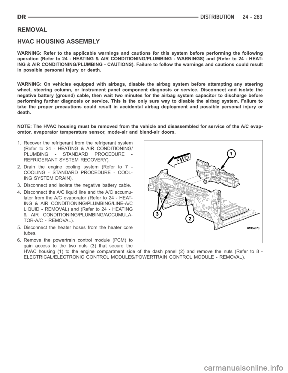
6. Remove the powertrain control module (PCM) to
gain access to the two nuts (3) that secure the
HVAC housing (1) to the engine compartment side of the dash panel (2) and remove the nuts (Refer to 8 -
ELECTRICAL/ELECTRONIC CONTROL MODULES/POWERTRAIN CONTROL MODULE - REMOVAL).
Page 5119 of 5267
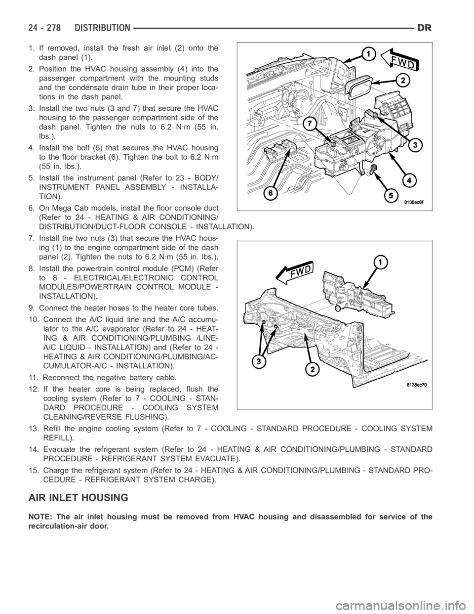
1. If removed, install the fresh air inlet (2) onto the
dash panel (1).
2. Position the HVAC housing assembly (4) into the
passenger compartment with the mounting studs
and the condensate drain tube in their proper loca-
tions in the dash panel.
3. Install the two nuts (3 and 7) that secure the HVAC
housing to the passenger compartment side of the
dash panel. Tighten the nuts to 6.2 Nꞏm (55 in.
lbs.).
4. Install the bolt (5) that secures the HVAC housing
to the floor bracket (6). Tighten the bolt to 6.2 Nꞏm
(55 in. lbs.).
5. Install the instrument panel (Refer to 23 - BODY/
INSTRUMENT PANEL ASSEMBLY - INSTALLA-
TION).
6. On Mega Cab models, install the floor console duct
(Refer to 24 - HEATING & AIR CONDITIONING/
DISTRIBUTION/DUCT-FLOOR CONSOLE - INSTALLATION).
7. Install the two nuts (3) that secure the HVAC hous-
ing (1) to the engine compartment side of the dash
panel (2). Tighten the nuts to 6.2 Nꞏm (55 in. lbs.).
8. Install the powertrain control module (PCM) (Refer
to 8 - ELECTRICAL/ELECTRONIC CONTROL
MODULES/POWERTRAIN CONTROL MODULE -
INSTALLATION).
9. Connect the heater hoses to the heater core tubes.
10. Connect the A/C liquid line and the A/C accumu-
lator to the A/C evaporator (Refer to 24 - HEAT-
ING & AIR CONDITIONING/PLUMBING /LINE-
A/C LIQUID - INSTALLATION) and (Refer to 24 -
HEATING & AIR CONDITIONING/PLUMBING/AC-
CUMULATOR-A/C - INSTALLATION).
11. Reconnect the negative battery cable.
12. If the heater core is being replaced, flush the
coolingsystem(Referto7-COOLING-STAN-
DARD PROCEDURE - COOLING SYSTEM
CLEANING/REVERSE FLUSHING).
13. Refill the engine cooling system (Refer to 7 - COOLING - STANDARD PROCEDURE - COOLING SYSTEM
REFILL).
14. Evacuate the refrigerant system (Refer to 24 - HEATING & AIR CONDITIONING/PLUMBING - STANDARD
PROCEDURE - REFRIGERANT SYSTEM EVACUATE).
15. Charge the refrigerant system (Refer to 24 - HEATING & AIR CONDITIONING/PLUMBING - STANDARD PRO-
CEDURE - REFRIGERANT SYSTEM CHARGE).
AIR INLET HOUSING
NOTE: The air inlet housing must be removed from HVAC housing and disassembled for service of the
recirculation-air door.