2006 DODGE RAM SRT-10 engine
[x] Cancel search: enginePage 4321 of 5267
TIRES
DESCRIPTION
TIRES
Tires are designed and engineered for each specific vehicle. They providethe best overall performance for normal
operation. The ride and handling characteristics match the vehicle’s requirements. With proper care they will give
excellent reliability, traction,skid resistance, and tread life.
Driving habits have more effect on tire life than any other factor. Carefuldrivers will obtain in most cases, much
greater mileage than severe use or careless drivers. A few of the driving habits which will shorten the life of any tire
are:
Rapid acceleration
Severe brake applications
High speed driving
Excessive speeds on turns
Striking curbs and other obstacles
Radial-ply tires are more prone to irregular tread wear. It is important tofollow the tire rotation interval (Refer to 22
- TIRES/WHEELS - STANDARD PROCEDURE). This will help to achieve a greater tread life.
TIRE IDENTIFICATION
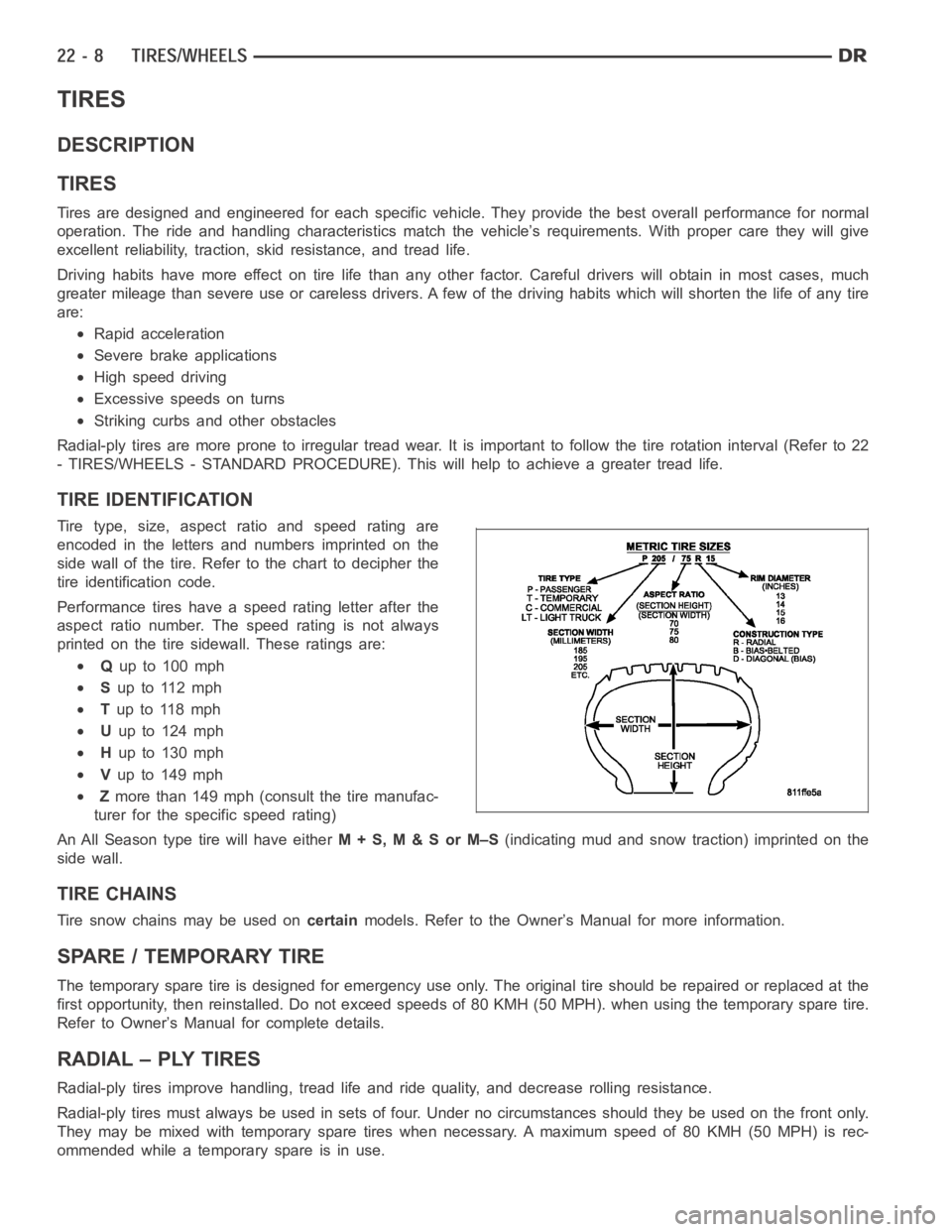
Tire type, size, aspect ratio and speed rating are
encoded in the letters and numbers imprinted on the
side wall of the tire. Refer to the chart to decipher the
tire identification code.
Performance tires have a speed rating letter after the
aspect ratio number. The speed rating is not always
printed on the tire sidewall. These ratings are:
Qup to 100 mph
Sup to 112 mph
Tup to 118 mph
Uup to 124 mph
Hup to 130 mph
Vup to 149 mph
Zmore than 149 mph (consult the tire manufac-
turer for the specific speed rating)
An All Season type tire will have eitherM+S,M&SorM–S(indicating mud and snow traction) imprinted on the
side wall.
TIRE CHAINS
Tire snow chains may be used oncertainmodels. Refer to the Owner’s Manual for more information.
SPARE / TEMPORARY TIRE
The temporary spare tire is designed for emergency use only. The original tire should be repaired or replaced at the
first opportunity, then reinstalled. Do not exceed speeds of 80 KMH (50 MPH). when using the temporary spare tire.
Refer to Owner’s Manual for complete details.
RADIAL – PLY TIRES
Radial-ply tires improve handling, tread life and ride quality, and decrease rolling resistance.
Radial-ply tires must always be used in sets of four. Under no circumstances should they be used on the front only.
They may be mixed with temporary spare tires when necessary. A maximum speedof80KMH(50MPH)isrec-
ommended while a temporary spare is in use.
Page 4323 of 5267
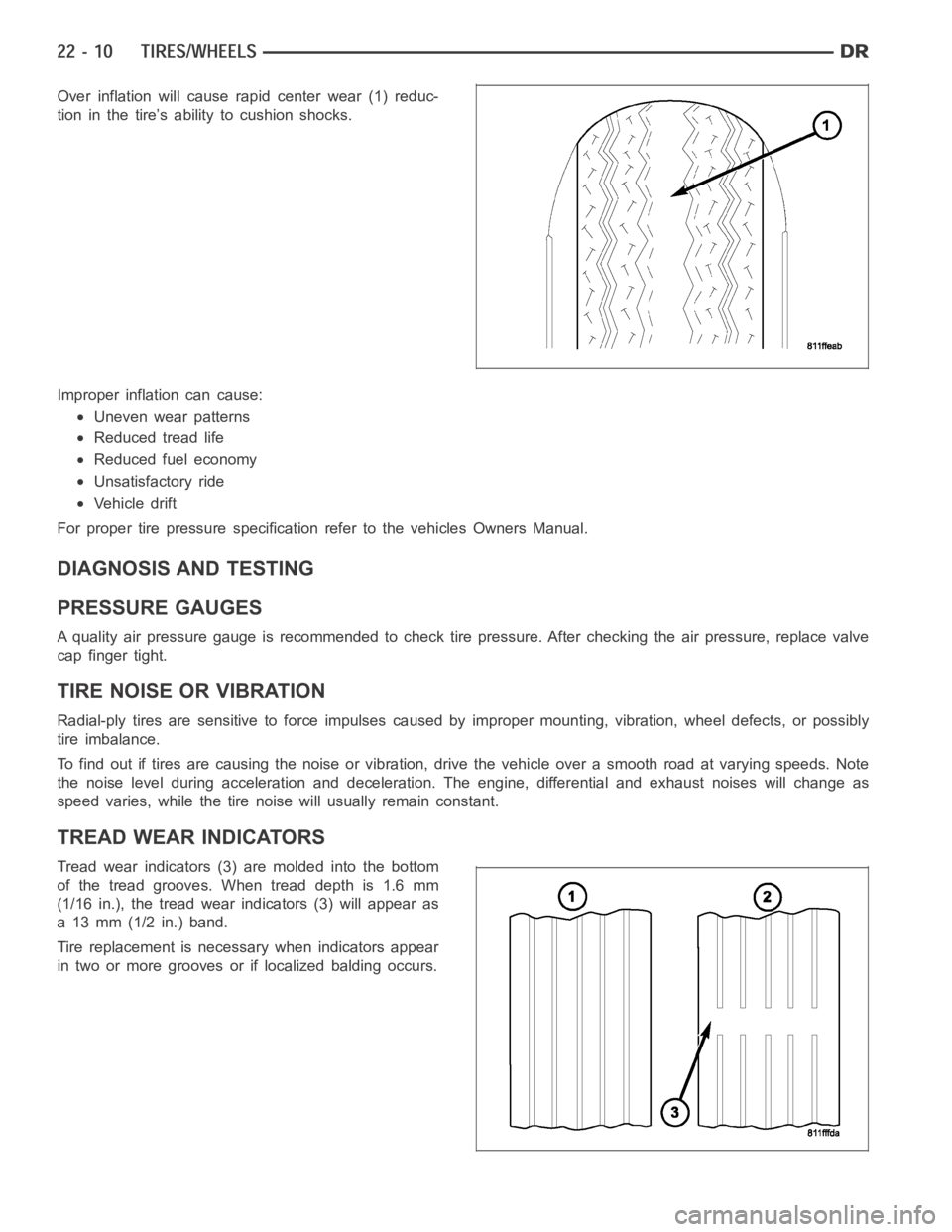
Over inflation will cause rapid center wear (1) reduc-
tion in the tire’s ability to cushion shocks.
Improper inflation can cause:
Uneven wear patterns
Reduced tread life
Reduced fuel economy
Unsatisfactory ride
Vehicle drift
For proper tire pressure specification refer to the vehicles Owners Manual.
DIAGNOSIS AND TESTING
PRESSURE GAUGES
A quality air pressure gauge is recommended to check tire pressure. After checking the air pressure, replace valve
cap finger tight.
TIRE NOISE OR VIBRATION
Radial-ply tires are sensitive to force impulses caused by improper mounting, vibration, wheel defects, or possibly
tire imbalance.
To find out if tires are causing the noise or vibration, drive the vehicle over a smooth road at varying speeds. Note
the noise level during acceleration and deceleration. The engine, differential and exhaust noises will change as
speed varies, while the tire noise will usually remain constant.
TREAD WEAR INDICATORS
Tread wear indicators (3) are molded into the bottom
of the tread grooves. When tread depth is 1.6 mm
(1/16 in.), the tread wear indicators (3) will appear as
a 13 mm (1/2 in.) band.
Tire replacement is necessary when indicators appear
in two or more grooves or if localized balding occurs.
Page 4340 of 5267
vehicle. If the leak occurs on left turns, hoist the left side of the vehicle. If the leak occurs on right turns, hoist
the right side of the vehicle. For hoisting recommendations (Refer to LUBRICATION & MAINTENANCE/HOIST-
ING - STANDARD PROCEDURE).
WATER LEAK DETECTION
To detect a water leak point-of-entry, do a water test and watch for water tracks or droplets forming on the inside of
the vehicle. If necessary, remove interior trim covers or panels to gain visual access to the leak area. If the hose
cannot be positioned without being held, have someone help do the water test.
Some water leaks must be tested for a considerable length of time to become apparent. When a leak appears, find
the highest point of the water track or drop. The highest point usually willshow the point of entry. After leak point
has been found, repair the leak and water test to verify that the leak has stopped.
Locating the entry point of water that is leaking into a cavity between panels can be difficult. The trapped water may
splash or run from the cavity, often at adistance from the entry point. Mostwater leaks of this type become appar-
ent after accelerating, stopping, turning, or when on an incline.
MIRROR INSPECTION METHOD
When a leak point area is visually obstructed, use a suitable mirror to gainvisual access. A mirror can also be used
to deflect light to a limited-access area to assist in locating a leak point.
BRIGHT LIGHT LEAK TEST METHOD
Some water leaks in the luggage compartment can be detected without water testing. Position the vehicle in a
brightly lit area. From inside the darkened luggage compartment inspect around seals and body seams. If neces-
sary, have a helper direct a drop light over the suspected leak areas aroundthe luggage compartment. If light is
visible through a normally sealed location, water could enter through theopening.
PRESSURIZED LEAK TEST METHOD
When a water leak into the passenger compartment cannot be detected by water testing, pressurize the passenger
compartment and soap test exterior ofthe vehicle. To pressurize the passenger compartment, close all doors and
windows, start engine, and set heater control to high blower in HEAT position. If engine can not be started, connect
a charger to the battery to ensure adequate voltage to the blower. With interior pressurized, apply dish detergent
solution to suspected leak area on the exterior of the vehicle. Apply detergent solution with spray device or soft
bristle brush. If soap bubbles occur at a body seam, joint, seal or gasket, the leak entry point could be at that
location.
WIND NOISE
Wind noise is the result of most air leaks. Air leaks can be caused by poor sealing, improper body component
alignment, body seam porosity, or missing plugs in the engine compartmentor door hinge pillar areas. All body
sealing points should be airtight in normal driving conditions. Moving sealing surfaces will not always seal airtight
under all conditions. At times, side glass or door seals will allow wind noise to be noticed in the passenger com-
partment during high cross winds. Over compensating on door or glass adjustments to stop wind noise that occurs
under severe conditions can cause premature seal wear and excessive closing or latching effort. After a repair pro-
cedure has been performed, test vehicle to verify noise has stopped beforereturning vehicle to use.
VISUAL INSPECTION BEFORE TESTS
Verify that floor and body plugs are in place and body components are aligned and sealed. If component alignment
or sealing is necessary, refer to the appropriate section of this group forproper procedures.
ROAD TESTING WIND NOISE
1. Drive the vehicle to verify the general location of the wind noise.
2. Apply 50 mm (2 in.) masking tape in 150 mm (6 in.) lengths along weatherstrips, weld seams or moldings. After
each length is applied, drive the vehicle. If noise goes away after a piece of tape is applied, remove tape, locate,
and repair defect.
Page 4471 of 5267
LATCH RELEASE CABLE/HANDLE ASSEMBLY
REMOVAL
REMOVAL
1.Removethehoodlatch(Referto23-BODY/
HOOD/LATCH - REMOVAL).
2. Remove the battery tray from the left side of the
engine compartment (Refer to 8 - ELECTRICAL/
BATTERY SYSTEM/TRAY - REMOVAL).
3. Remove the three hood release cable retainers
from the upper radiator crossmember and the left
fender rail.
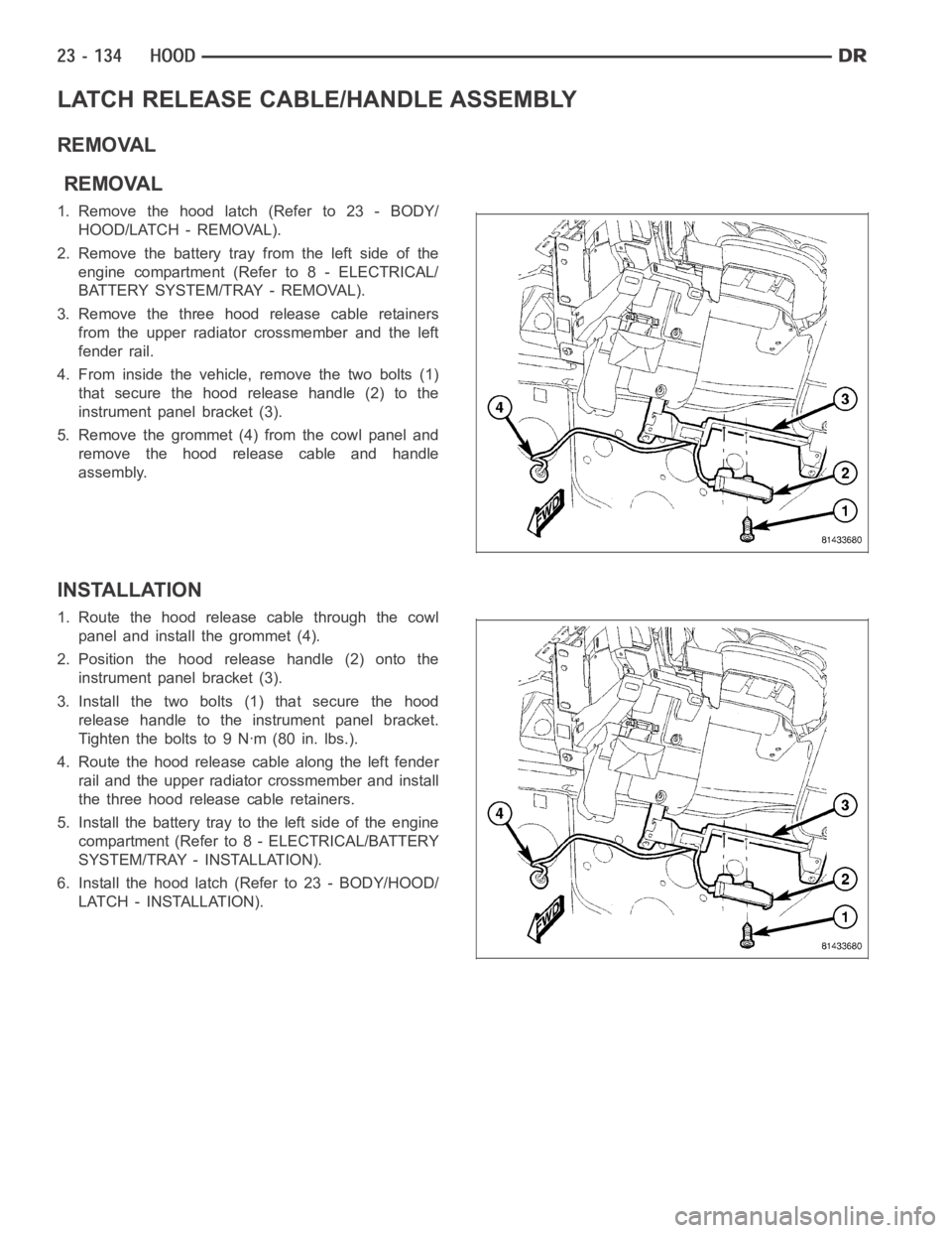
4. From inside the vehicle, remove the two bolts (1)
that secure the hood release handle (2) to the
instrument panel bracket (3).
5. Remove the grommet (4) from the cowl panel and
remove the hood release cable and handle
assembly.
INSTALLATION
1. Route the hood release cable through the cowl
panel and install the grommet (4).
2. Position the hood release handle (2) onto the
instrument panel bracket (3).
3. Install the two bolts (1) that secure the hood
release handle to the instrument panel bracket.
Tightentheboltsto9Nꞏm(80in.lbs.).
4. Route the hood release cable along the left fender
rail and the upper radiator crossmember and install
the three hood release cable retainers.
5. Install the battery tray to the left side of the engine
compartment (Refer to 8 - ELECTRICAL/BATTERY
SYSTEM/TRAY - INSTALLATION).
6. Install the hood latch (Refer to 23 - BODY/HOOD/
LATCH - INSTALLATION).
Page 4609 of 5267
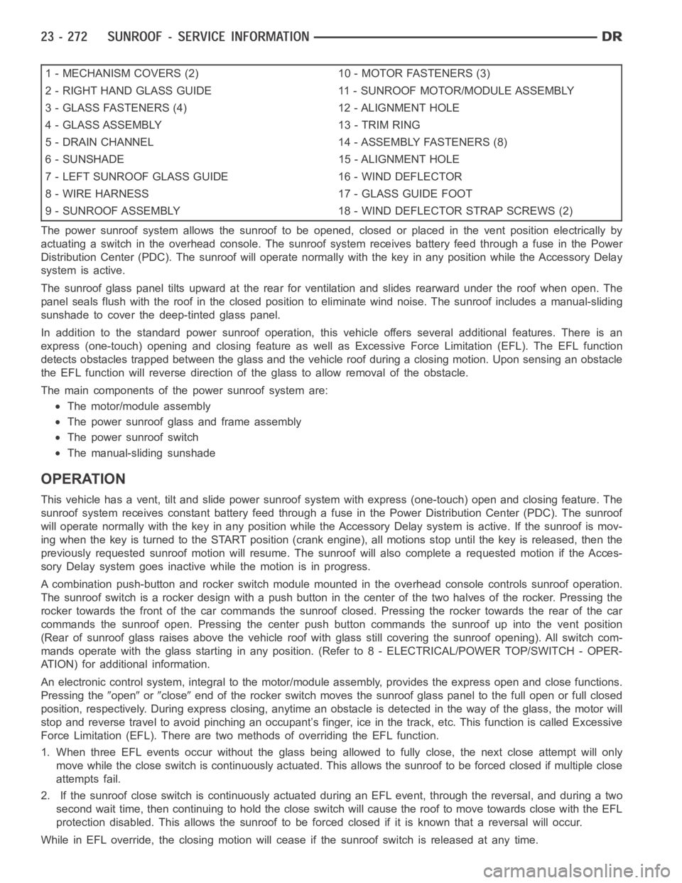
1 - MECHANISM COVERS (2) 10 - MOTOR FASTENERS (3)
2 - RIGHT HAND GLASS GUIDE 11 - SUNROOF MOTOR/MODULE ASSEMBLY
3 - GLASS FASTENERS (4) 12 - ALIGNMENT HOLE
4 - GLASS ASSEMBLY 13 - TRIM RING
5 - DRAIN CHANNEL 14 - ASSEMBLY FASTENERS (8)
6 - SUNSHADE 15 - ALIGNMENT HOLE
7 - LEFT SUNROOF GLASS GUIDE 16 - WIND DEFLECTOR
8 - WIRE HARNESS 17 - GLASS GUIDE FOOT
9 - SUNROOF ASSEMBLY 18 - WIND DEFLECTOR STRAP SCREWS (2)
The power sunroof system allows the sunroof to be opened, closed or placed in the vent position electrically by
actuating a switch in the overhead console. The sunroof system receives battery feed through a fuse in the Power
Distribution Center (PDC). The sunroof will operate normally with the keyin any position while the Accessory Delay
system is active.
The sunroof glass panel tilts upward at the rear for ventilation and slidesrearward under the roof when open. The
panel seals flush with the roof in the closed position to eliminate wind noise. The sunroof includes a manual-sliding
sunshade to cover the deep-tinted glass panel.
In addition to the standard power sunroof operation, this vehicle offers several additional features. There is an
express (one-touch) opening and closing feature as well as Excessive Force Limitation (EFL). The EFL function
detects obstacles trapped between the glass and the vehicle roof during a closing motion. Upon sensing an obstacle
the EFL function will reverse direction of the glass to allow removal of theobstacle.
The main components of thepower sunroof system are:
The motor/module assembly
The power sunroof glass and frame assembly
The power sunroof switch
The manual-sliding sunshade
OPERATION
This vehicle has a vent, tilt and slide power sunroof system with express (one-touch) open and closing feature. The
sunroof system receives constant battery feed through a fuse in the Power Distribution Center (PDC). The sunroof
will operate normally with the key in any position while the Accessory Delay system is active. If the sunroof is mov-
ing when the key is turned to the START position (crank engine), all motionsstop until the key is released, then the
previously requested sunroof motion will resume. The sunroof will also complete a requested motion if the Acces-
sory Delay system goes inactivewhile the motion is in progress.
A combination push-button and rocker switch module mounted in the overhead console controls sunroof operation.
The sunroof switch is a rocker design with a push button in the center of the two halves of the rocker. Pressing the
rocker towards the front of the car commands the sunroof closed. Pressing the rocker towards the rear of the car
commands the sunroof open. Pressing the center push button commands the sunroof up into the vent position
(Rear of sunroof glass raises above the vehicle roof with glass still covering the sunroof opening). All switch com-
mands operate with the glass startingin any position. (Refer to 8 - ELECTRICAL/POWER TOP/SWITCH - OPER-
ATION) for additional information.
An electronic control system, integralto the motor/module assembly, provides the express open and close functions.
Pressing the
openorcloseend of the rocker switch moves the sunroof glass panel to the full open or fullclosed
position, respectively. During express closing, anytime an obstacle is detected in the way of the glass, the motor will
stop and reverse travel to avoid pinching an occupant’s finger, ice in the track, etc. This function is called Excessive
Force Limitation (EFL). There are two methods of overriding the EFL function.
1. When three EFL events occur without the glass being allowed to fully close, the next close attempt will only
move while the close switch is continuously actuated. This allows the sunrooftobeforcedclosedifmultipleclose
attempts fail.
2. If the sunroof close switch is continuously actuated during an EFL event, through the reversal, and during a two
second wait time, then continuing to hold the close switch will cause the roof to move towards close with the EFL
protection disabled. This allows the sunroof to be forced closed if it is known that a reversal will occur.
While in EFL override, the closing motion will cease if the sunroof switch is released at any time.
Page 4704 of 5267
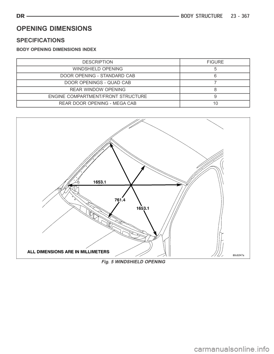
OPENING DIMENSIONS
SPECIFICATIONS
BODY OPENING DIMENSIONS INDEX
DESCRIPTION FIGURE
WINDSHIELD OPENING 5
DOOR OPENING - STANDARD CAB 6
DOOR OPENINGS - QUAD CAB 7
REAR WINDOW OPENING 8
ENGINE COMPARTMENT/FRONT STRUCTURE 9
REAR DOOR OPENING - MEGA CAB 10
Fig. 5 WINDSHIELD OPENING
Page 4706 of 5267
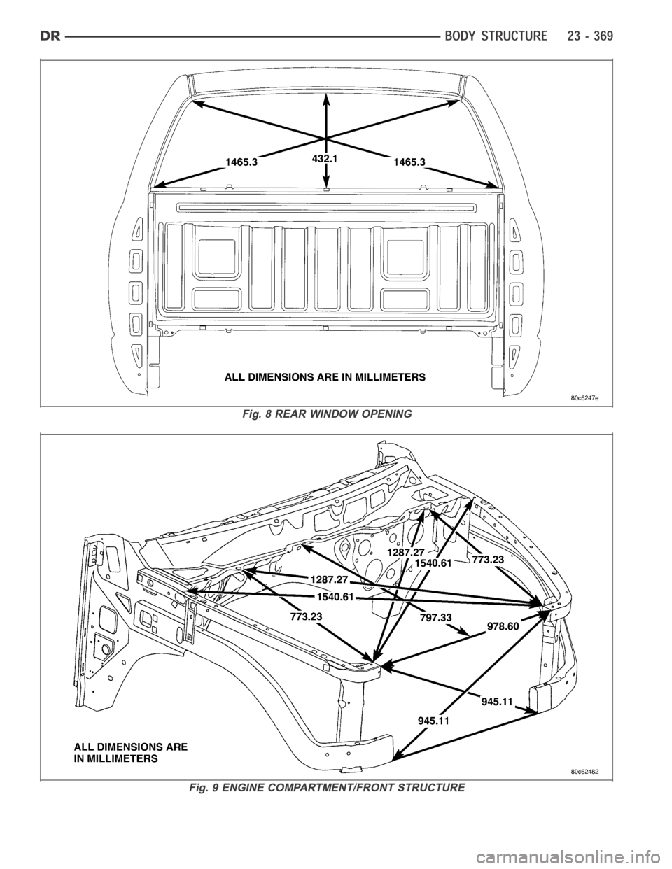
Fig. 8 REAR WINDOW OPENING
Fig. 9 ENGINE COMPARTMENT/FRONT STRUCTURE
Page 4877 of 5267
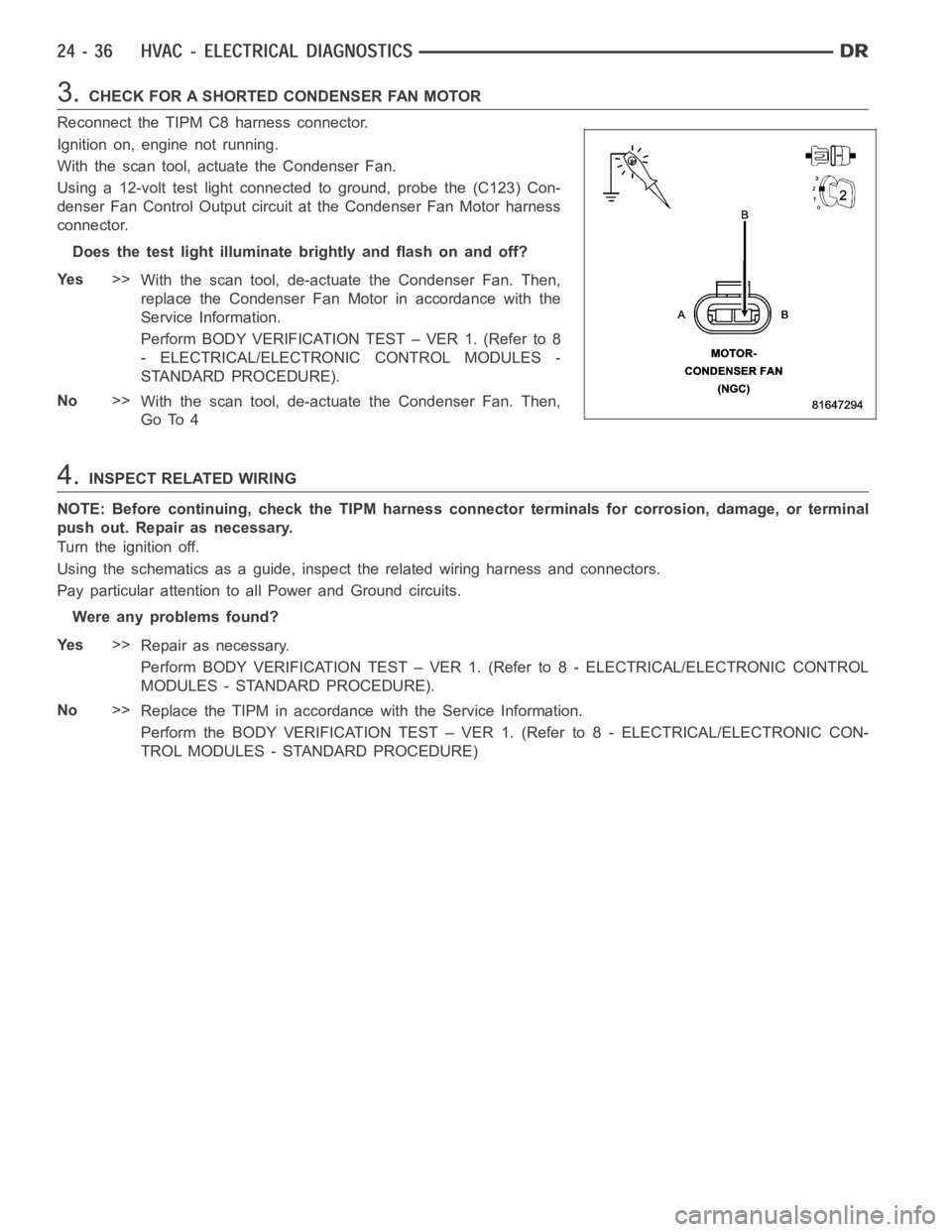
3.CHECK FOR A SHORTED CONDENSER FAN MOTOR
Reconnect the TIPM C8 harness connector.
Ignition on, engine not running.
With the scan tool, actuate the Condenser Fan.
Using a 12-volt test light connected to ground, probe the (C123) Con-
denser Fan Control Output circuit at the Condenser Fan Motor harness
connector.
Does the test light illuminate brightly and flash on and off?
Ye s>>
With the scan tool, de-actuate the Condenser Fan. Then,
replace the Condenser Fan Motor in accordance with the
Service Information.
Perform BODY VERIFICATION TEST – VER 1. (Refer to 8
- ELECTRICAL/ELECTRONIC CONTROL MODULES -
STANDARD PROCEDURE).
No>>
With the scan tool, de-actuate the Condenser Fan. Then,
Go To 4
4.INSPECT RELATED WIRING
NOTE: Before continuing, check the TIPM harness connector terminals for corrosion, damage, or terminal
push out. Repair as necessary.
Turn the ignition off.
Using the schematics as a guide, inspect the related wiring harness and connectors.
Pay particular attention to all Power and Ground circuits.
Were any problems found?
Ye s>>
Repair as necessary.
Perform BODY VERIFICATION TEST – VER 1. (Refer to 8 - ELECTRICAL/ELECTRONIC CONTROL
MODULES - STANDARD PROCEDURE).
No>>
Replace the TIPM in accordance with the Service Information.
Perform the BODY VERIFICATION TEST – VER 1. (Refer to 8 - ELECTRICAL/ELECTRONIC CON-
TROL MODULES - STANDARD PROCEDURE)