2006 DODGE RAM SRT-10 engine
[x] Cancel search: enginePage 3959 of 5267
VALVE-TORQUE CONVERTER DRAINBACK
DESCRIPTION
GAS ENGINES
The drainback valve is located in the transmission cooler outlet (pressure) line.
DIESEL ENGINE
The converter drainback check valve is located in the in the TOC pressure - supply line, between the engine
mounted TOC and the air to oil TOC.
OPERATION
GAS ENGINES
The valve prevents fluid from draining from the converter into the cooler and lines when the vehicle is shut down for
lengthy periods. Production valves have a hose nipple at one end, while theopposite end is threaded for a flare
fitting. All valves have an arrow (or similar mark) to indicate direction of flow through the valve.
DIESEL ENGINE
The valve prevents fluid from draining from the converter into the cooler and lines when the vehicle is shut down for
lengthy periods. Production valves have pipe thread on one end, while the opposite end is threaded for a flare
fitting, and are threaded into the oil cooler mounted on the side of the engine. All valves have an arrow (or similar
mark) to indicate direction of flow through the valve.
STANDARD PROCEDURE
GAS ENGINES
The converter drainback check valve is located in the cooler outlet (pressure) line near the radiator tank. The valve
prevents fluid drainback when the vehicle is parked for lengthy periods. The valve check ball is spring loaded and
has an opening pressure of approximately 2 psi.
The valve is serviced as an assembly; it is not repairable. Do not clean the valve if restricted, or contaminated by
sludge, or debris. If the valve fails, or if a transmission malfunction occurs that generates significant amounts of
sludge and/or clutch particles and metal shavings, the valve must be replaced.
If the valve is restricted, installed backwards, or in the wrong line, it will cause an transmission overheating condition
and possible transmission failure.
CAUTION: The drainback valve is a one-way flow device. It must be properly orientedintermsofflowdirec-
tion for the cooler to function properly. The valve must be installed in thepressure line. Otherwise flow will
be blocked and would cause an transmission overheating condition and eventual transmission failure.
DIESEL ENGINE
The converter drainback check valve is located in the in the TOC pressure - supply line, between the engine
mounted transmission oil cooler and the air to oil transmission oil cooler. The valve prevents fluid drainback when
the vehicle is parked for lengthy periods. The valve check ball is spring loaded and has an opening pressure of
approximately 2 psi.
The valve is serviced as an assembly; it is not repairable. Do not clean the valve if restricted, or contaminated by
sludge, or debris. If the valve fails, or if a transmission malfunction occurs that generates significant amounts of
sludge and/or clutch particles and metal shavings, the valve must be replaced.
If the valve is restricted, installed backwards, or in the wrong line, it will cause an transmission overheating condition
and possible transmission failure.
Page 3963 of 5267
SENSOR-TRANSMISSION RANGE
DESCRIPTION
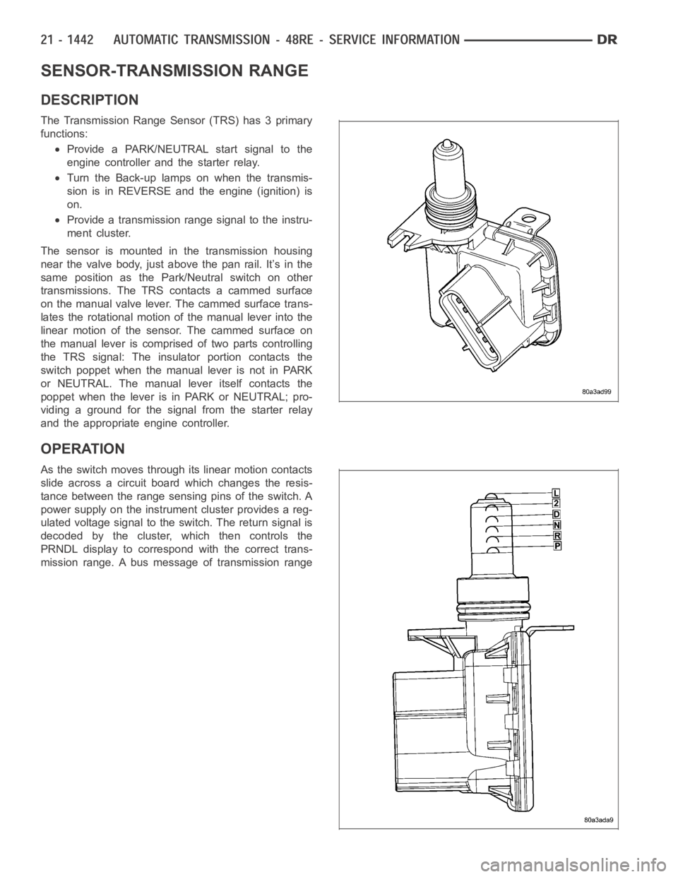
The Transmission Range Sensor (TRS) has 3 primary
functions:
Provide a PARK/NEUTRAL start signal to the
engine controller and the starter relay.
Turn the Back-up lamps on when the transmis-
sion is in REVERSE and the engine (ignition) is
on.
Provide a transmission range signal to the instru-
ment cluster.
The sensor is mounted in the transmission housing
near the valve body, just above the pan rail. It’s in the
same position as the Park/Neutral switch on other
transmissions. The TRS contacts a cammed surface
on the manual valve lever. The cammed surface trans-
lates the rotational motion of the manual lever into the
linear motion of the sensor. The cammed surface on
the manual lever is comprised of two parts controlling
the TRS signal: The insulator portion contacts the
switch poppet when the manual lever is not in PARK
or NEUTRAL. The manual lever itself contacts the
poppet when the lever is in PARK or NEUTRAL; pro-
viding a ground for the signal from the starter relay
and the appropriate engine controller.
OPERATION
As the switch moves through its linear motion contacts
slide across a circuit board which changes the resis-
tance between the range sensing pins of the switch. A
power supply on the instrument cluster provides a reg-
ulated voltage signal to the switch. The return signal is
decoded by the cluster, which then controls the
PRNDL display to correspond with the correct trans-
mission range. A bus message of transmission range
Page 3974 of 5267
REGULATOR VALVE
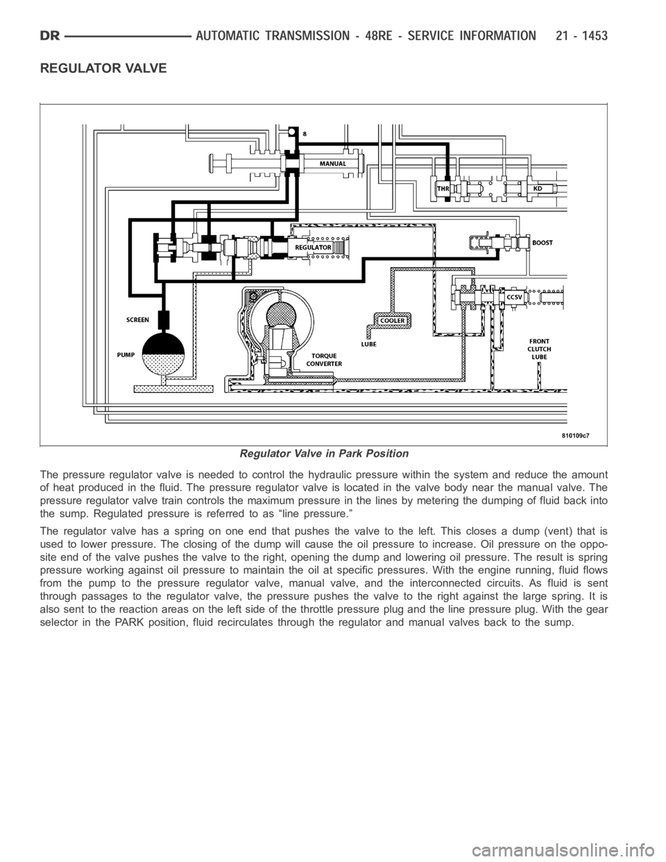
The pressure regulator valve is needed to control the hydraulic pressure within the system and reduce the amount
of heat produced in the fluid. The pressure regulator valve is located in the valve body near the manual valve. The
pressure regulator valve train controls the maximum pressure in the linesby metering the dumping of fluid back into
the sump. Regulated pressure is referred to as “line pressure.”
The regulator valve has a spring on one end that pushes the valve to the left.This closes a dump (vent) that is
used to lower pressure. The closing of the dump will cause the oil pressure to increase. Oil pressure on the oppo-
site end of the valve pushes the valve to the right, opening the dump and lowering oil pressure. The result is spring
pressure working against oil pressureto maintain the oil at specific pressures. With the engine running, fluid flows
from the pump to the pressure regulator valve, manual valve, and the interconnected circuits. As fluid is sent
through passages to the regulator valve, the pressure pushes the valve to the right against the large spring. It is
also sent to the reaction areas on the left side of the throttle pressure plug and the line pressure plug. With the gear
selector in the PARK position, fluid recirculates through the regulator and manual valves back to the sump.
Regulator Valve in Park Position
Page 3987 of 5267
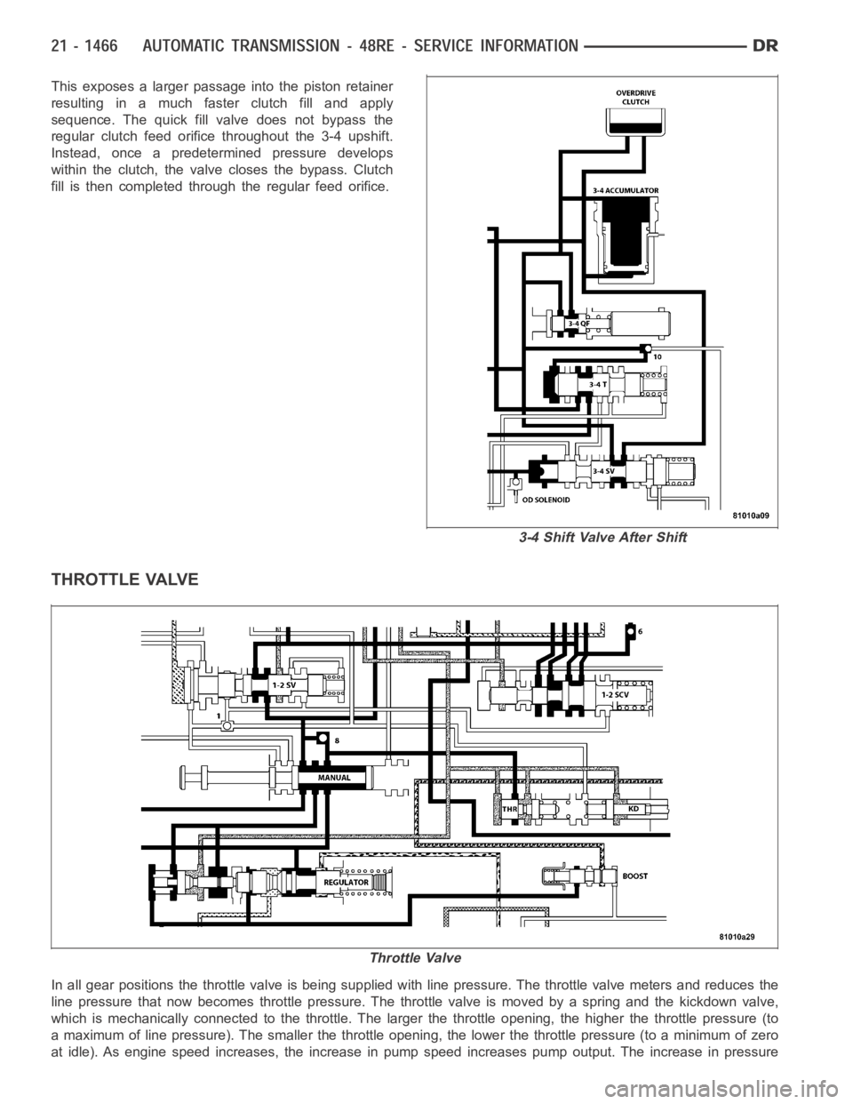
This exposes a larger passage into the piston retainer
resulting in a much faster clutch fill and apply
sequence. The quick fill valve does not bypass the
regular clutch feed orifice throughout the 3-4 upshift.
Instead, once a predetermined pressure develops
within the clutch, the valve closes the bypass. Clutch
fill is then completed through the regular feed orifice.
THROTTLE VALVE
In all gear positions the throttle valve is being supplied with line pressure. The throttle valve meters and reduces the
line pressure that now becomes throttle pressure. The throttle valve is moved by a spring and the kickdown valve,
which is mechanically connected to the throttle. The larger the throttle opening, the higher the throttle pressure (to
a maximum of line pressure). The smaller the throttle opening, the lower thethrottlepressure(toaminimumofzero
at idle). As engine speed increases, the increase in pump speed increases pump output. The increase in pressure
3-4 Shift Valve After Shift
Throttle Valve
Page 3988 of 5267
and volume must be regulated to maintain the balance within the transmission. To do this, throttle pressure is routed
tothereactionareaontherightsideofthethrottlepressureplug(intheregulator valve).
The higher engine speed and line pressure would open the vent too far and reduce line pressure too much. Throttle
pressure, which increases with engine speed (throttle opening), is used to oppose the movement of the pressure
valve to help control the metering passage at the vent. The throttle pressure is combined with spring pressure to
reduce the force of the throttle pressure plug on the pressure valve. The larger spring at the right closes the reg-
ulator valve passage and maintains or increases line pressure. The increased line pressure works against the reac-
tion area of the line pressure plug and the reaction area left of land #3 simultaneously moves the regulator valve
train to the right and controls the metering passage.
The kickdown valve, along with the throttle valve, serve to delay upshiftsuntil the correct vehicle speed has been
reached. It also controls downshifts upon driver demand, or increased engine load. If these valves were not in
place, the shift points would be at the same speed for all throttle positions. The kickdown valve is actuated by a
cam connected to the throttle. This is accomplished through either a linkage or a cable. The cam forces the kick-
down valve toward the throttle valve compressing the spring between them and moving the throttle valve. As the
throttle valve land starts to uncover its port, line pressure is “metered”out into the circuits and viewed as throttle
pressure. This increased throttle pressure is metered out into the circuits it is applied to: the 1-2 and 2-3 shift
valves. When the throttle pressure is high enough, a 3-2 downshift will occur. If the vehicle speed is low enough, a
2-1 downshift will occur.
Page 4023 of 5267
When Monitored:
With the ignition on.
Set Condition:
Transfer Case Range Select Switch voltage less than 0.1568 volts for 5 seconds
Possible Causes
(K77) 5 VOLT SELECTOR SWITCH SUPPLY CIRCUIT OPEN
(K77) 5 VOLT SELECTOR SWITCH SUPPLY CIRCUIT SHORTED TO GROUND
(K977) MODE SELECT CIRCUIT OPEN
(K977) MODE SELECT CIRCUIT SHORT TO GROUND
TRANSFER CASE SELECTOR SWITCH
INSTRUMENT CLUSTER
Diagnostic Test
1.TRANSFER CASE SWITCH VOLTAGE LESS THAN 0.2 VOLTS
Ignition on, engine not running.
With the scan tool under Instrument Cluster, read the Transfer Case Switchvoltage.
Is the voltage less than 0.2 volts?
Ye s>>
Go To 2
No>>
Go To 8
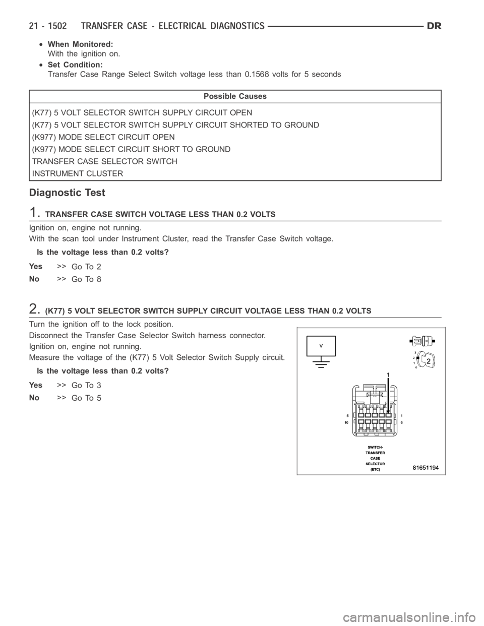
2.(K77) 5 VOLT SELECTOR SWITCH SUPPLY CIRCUIT VOLTAGE LESS THAN 0.2 VOLTS
Turn the ignition off to the lock position.
Disconnect the Transfer Case Selector Switch harness connector.
Ignition on, engine not running.
Measure the voltage of the (K77) 5 Volt Selector Switch Supply circuit.
Is the voltage less than 0.2 volts?
Ye s>>
Go To 3
No>>
Go To 5
Page 4025 of 5267
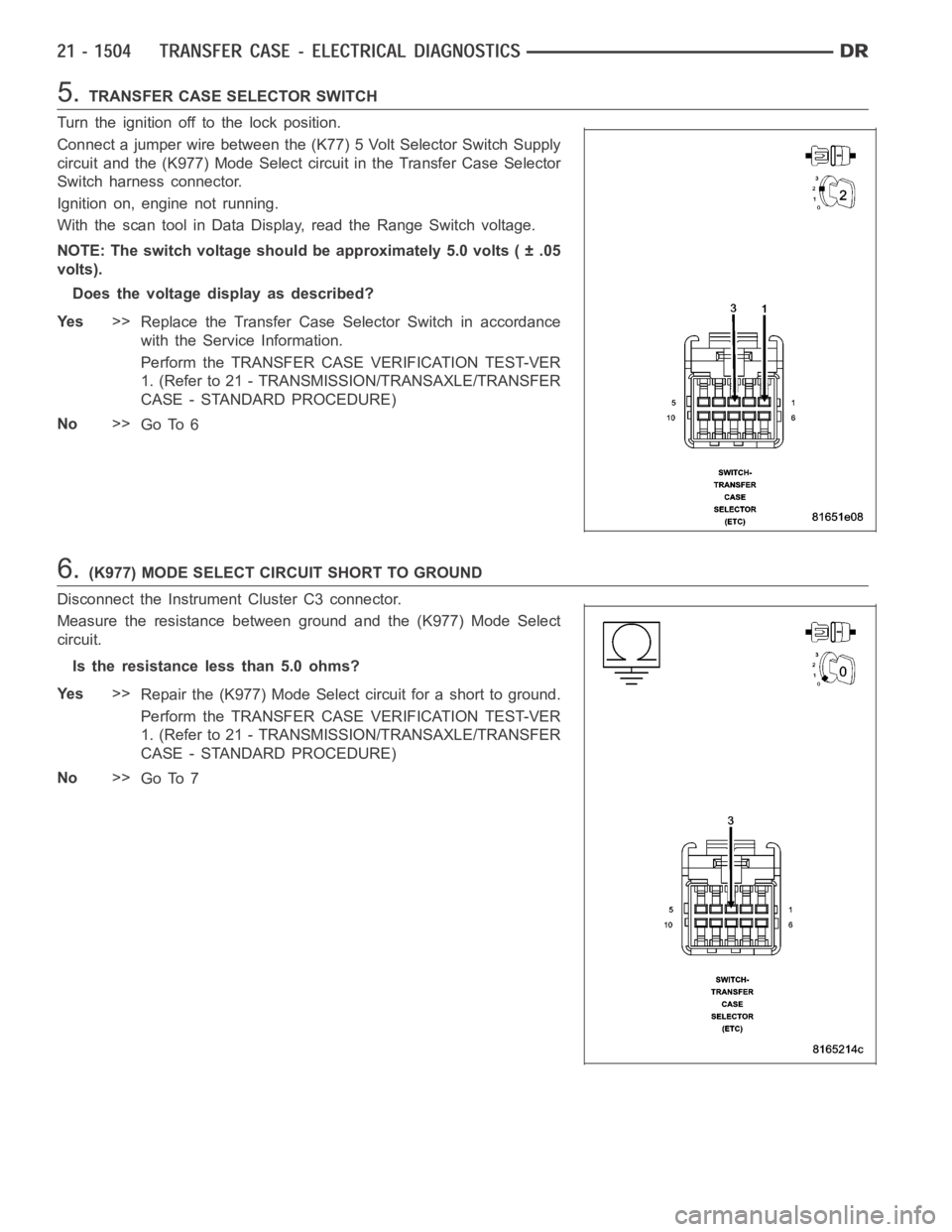
5.TRANSFER CASE SELECTOR SWITCH
Turn the ignition off to the lock position.
Connect a jumper wire between the (K77) 5 Volt Selector Switch Supply
circuit and the (K977) Mode Select circuit in the Transfer Case Selector
Switch harness connector.
Ignition on, engine not running.
With the scan tool in Data Display, read the Range Switch voltage.
NOTE: The switch voltage should be approximately 5.0 volts ( ± .05
volts).
Does the voltage display as described?
Ye s>>
Replace the Transfer Case Selector Switch in accordance
with the Service Information.
Perform the TRANSFER CASE VERIFICATION TEST-VER
1. (Refer to 21 - TRANSMISSION/TRANSAXLE/TRANSFER
CASE - STANDARD PROCEDURE)
No>>
Go To 6
6.(K977) MODE SELECT CIRCUIT SHORT TO GROUND
Disconnect the Instrument Cluster C3 connector.
Measure the resistance between ground and the (K977) Mode Select
circuit.
Is the resistance less than 5.0 ohms?
Ye s>>
Repair the (K977) Mode Select circuit for a short to ground.
Perform the TRANSFER CASE VERIFICATION TEST-VER
1. (Refer to 21 - TRANSMISSION/TRANSAXLE/TRANSFER
CASE - STANDARD PROCEDURE)
No>>
Go To 7
Page 4028 of 5267
When Monitored:
With the ignition on.
Set Condition:
Transfer Case Range Select Switch voltage greater than 4.86 volts for 5 seconds
Possible Causes
(K77) 5 VOLT SELECTOR SWITCH SUPPLY CIRCUIT SHORTED TO VOLTAGE
(K977) MODE SELECT CIRCUIT SHORTED TO VOLTAGE
(K977) MODE SELECT CIRCUIT OPEN
(Z905) TRANSFER CASE SELECTOR SWITCH GROUND CIRCUIT OPEN
TRANSFER CASE SELECTOR SWITCH
INSTRUMENT CLUSTER
Diagnostic Test
1.TCASE SWITCH VOLTAGE ABOVE 4.8 VOLTS
Ignition on, engine not running.
With the scan tool under Instrument Cluster, read the Transfer Case Switchvoltage.
Is the volage above 4.8 volts?
Ye s>>
Go To 2
No>>
Go to 8
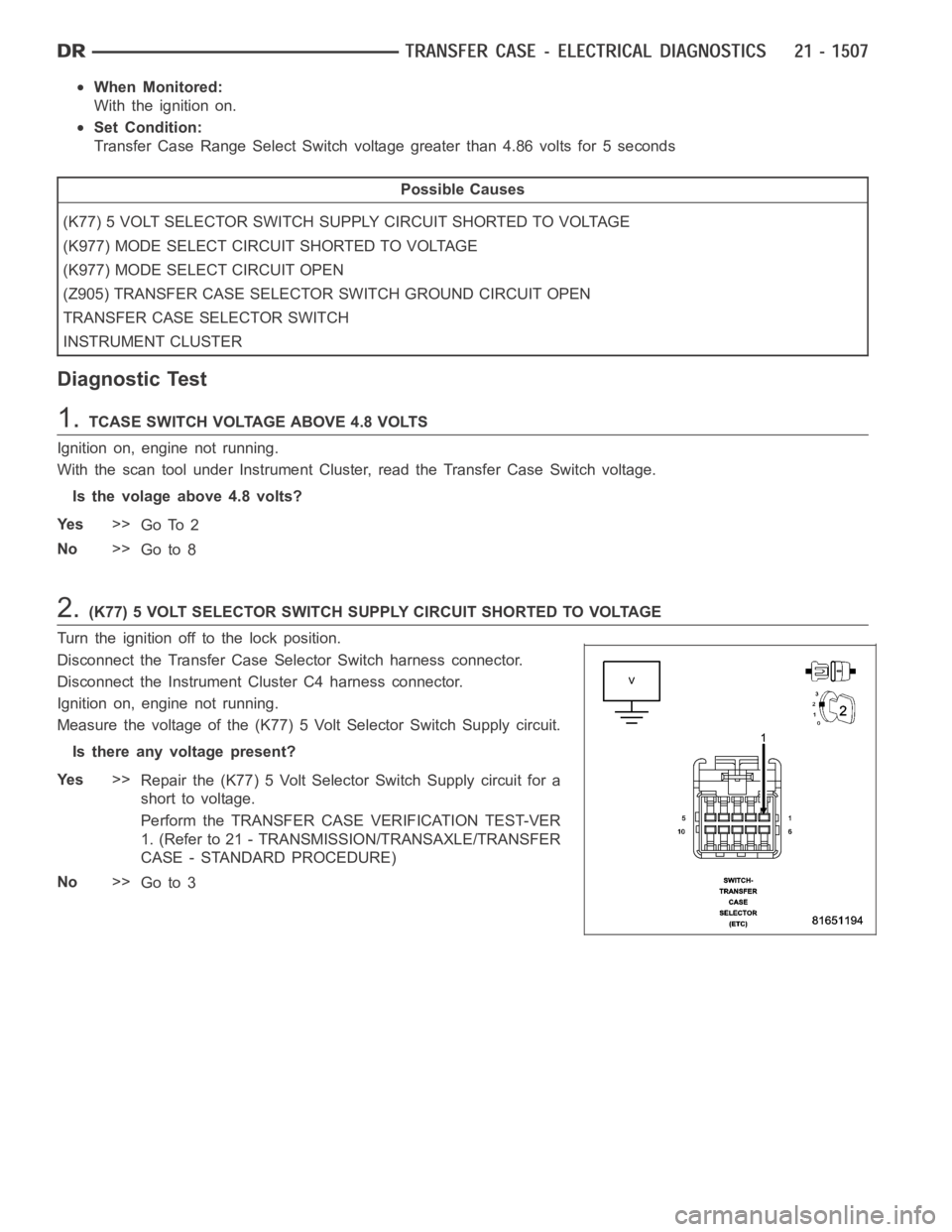
2.(K77) 5 VOLT SELECTOR SWITCH SUPPLY CIRCUIT SHORTED TO VOLTAGE
Turn the ignition off to the lock position.
Disconnect the Transfer Case Selector Switch harness connector.
Disconnect the Instrument Cluster C4 harness connector.
Ignition on, engine not running.
Measure the voltage of the (K77) 5 Volt Selector Switch Supply circuit.
Is there any voltage present?
Ye s>>
Repair the (K77) 5 Volt Selector Switch Supply circuit for a
short to voltage.
Perform the TRANSFER CASE VERIFICATION TEST-VER
1. (Refer to 21 - TRANSMISSION/TRANSAXLE/TRANSFER
CASE - STANDARD PROCEDURE)
No>>
Go to 3