Page 3945 of 5267
ACTUATOR-THROTTLE VALVE
DESCRIPTION
On vehicles equipped with a Cummins diesel engine,
the transmission throttle valve cable has been replace
by the transmission throttle valve actuator (TTVA). The
TTVA consists of an electric DC motor, two potentiom-
eters, and a gear drive system. The TTVA is mechan-
ically connected to the transmission throttle valve in
the valve body by the “D” shaped opening in the bot-
tom of the TTVA shaft. Changes in the TTVA position
are therefore transferred to the throttle valve and
cause changes in the transmission throttle pressure.
REMOVAL
1. Remove the bolts (2) holding the transmission
throttle valve actuator (TTVA) (1) to the transmis-
sion case.
2. Allow the TTVA (1) to rotate clockwise away from
the transmission.
Page 3947 of 5267
4. Rotate the TTVA (1) to the transmission case and
install the bolts (2) to hold the TTVA to the trans-
mission.
5. Tighten the bolts to 8.5 Nꞏm (75 in.lbs.).
6. Initialize the TTVA (Refer to 21 - TRANSMISSION/
AUTOMATIC - 48RE/THROTTLE VALVE ACTUA-
TOR - ADJUSTMENTS).
ADJUSTMENTS
ADJUSTMENT
The Transmission Throttle Valve Actuator (TTVA) does not require any mechanical adjustments. All changes in throt-
tle valve position are controlled by the Engine Control Module (ECM).
The TTVA does require an initialization period after the actuator has beenremoved or replaced. After the actuator
has been removed or replaced, move the iginition to the ON position for thirty (30) seconds. This will allow the ECM
sufficient time to perform the internal calibration procedures to learn the TTVA’s current “zero” position. Once this is
done, check the ECM for diagnostic trouble codes (DTCs). If no DTCs are set relating to the TTVA, the TTVA is fully
calibrated and ready for use.
Page 3948 of 5267
CABLE-THROTTLE VALVE
DESCRIPTION
Transmission throttle valve cable (1) adjustment is
extremely important to proper operation. This adjust-
ment positions the throttle valve, which controls shift
speed, quality, and part-throttle downshift sensitivity.
If cable setting is too loose, early shifts and slippage
between shifts may occur. If the setting is too tight,
shifts may be delayed and part throttle downshifts may
be very sensitive.
The transmission throttlevalveisoperatedbyacam
on the throttle lever. The throttle lever is operated by
an adjustable cable (3). The cable is attached to an
arm mounted on the throttle lever shaft. A retaining
clip (2) at the engine-end of the cable is removed to
provide for cable adjustment. The retaining clip is then
installedbackontothethrottlevalvecabletolockin
the adjustment.
Page 3952 of 5267
CONVERTER-TORQUE
DESCRIPTION
The torque converter is a hydraulic device that cou-
ples the engine crankshaft to the transmission. The
torque converter consists of an outer shell with an
internal turbine (1), a stator (4), an overrunning clutch,
an impeller (2), and an electronically applied converter
clutch (6). The converterclutch provides reduced
engine speed and greater fuel economy when
engaged. Clutch engagement also provides reduced
transmission fluid temperatures. The torque converter
hub drives the transmission oil (fluid) pump.
The torque converter is a sealed, welded unit that is
not repairable and is serviced as an assembly.
CAUTION: The torque converter must be replaced
if a transmission failure resulted in large amounts
of metal or fiber contamination in the fluid.
Page 3953 of 5267
IMPELLER
The impeller is an integral part of the converter housing. The impeller consists of curved blades placed radially
along the inside of the housing on the transmission side of the converter. As the converter housing is rotated by the
engine, so is the impeller, because they are one and the same and are the driving members of the system.
Impeller
1 - ENGINE FLEXPLATE 4 - ENGINE ROTATION
2 - OIL FLOW FROM IMPELLER SECTION INTO TURBINE
SECTION5 - ENGINE ROTATION
3 - IMPELLER VANES AND COVER ARE INTEGRAL
Page 3954 of 5267
TURBINE
The turbine is the output, or driven, member of the converter. The turbine is mounted within the housing opposite
the impeller, but is not attached to the housing. The input shaft is inserted through the center of the impeller and
splined into the turbine. The design of the turbine is similar to the impeller, except the blades of the turbine are
curved in the opposite direction.
STATOR
The stator assembly is mounted on a stationary shaft
which is an integral part of the oil pump. The stator
contains an over-running clutch (1-4), which allows the
stator to rotate only in a clockwise direction. When the
stator is locked against theover-runningclutch,the
torque multiplication feature of the torque converter is
operational.
Turbine
1 - TURBINE VANE 4 - PORTION OF TORQUE CONVERTER COVER
2 - ENGINE ROTATION 5 - ENGINE ROTATION
3 - INPUT SHAFT 6 - OIL FLOW WITHIN TURBINE SECTION
Page 3956 of 5267

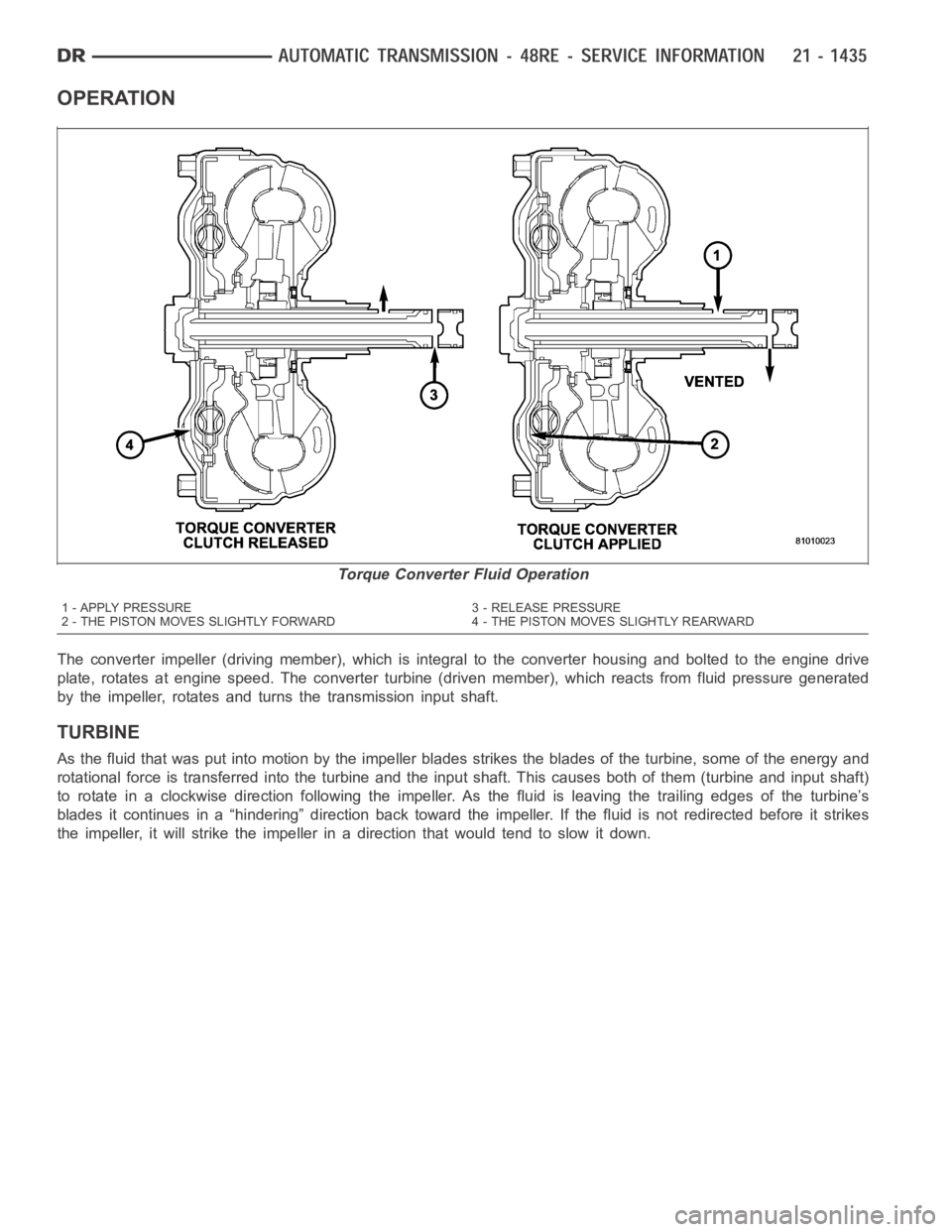
OPERATION
The converter impeller (driving member), which is integral to the converter housing and bolted to the engine drive
plate, rotates at engine speed. The converter turbine (driven member), which reacts from fluid pressure generated
by the impeller, rotates and turns the transmission input shaft.
TURBINE
As the fluid that was put into motion bythe impeller blades strikes the blades of the turbine, some of the energy and
rotational force is transferred into the turbine and the input shaft. Thiscauses both of them (turbine and input shaft)
to rotate in a clockwise direction following the impeller. As the fluid is leaving the trailing edges of the turbine’s
blades it continues in a “hindering” direction back toward the impeller. If the fluid is not redirected before it strikes
the impeller, it will strike the impeller in a direction that would tend to slow it down.
Torque Converter Fluid Operation
1 - APPLY PRESSURE 3 - RELEASE PRESSURE
2 - THE PISTON MOVES SLIGHTLY FORWARD 4 - THE PISTON MOVES SLIGHTLY REARWARD
Page 3957 of 5267

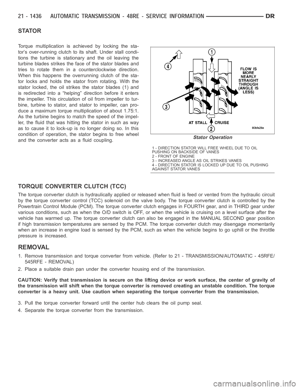
STATOR
Torque multiplication is achieved by locking the sta-
tor’s over-running clutch to its shaft. Under stall condi-
tions the turbine is stationary and the oil leaving the
turbine blades strikes the face of the stator blades and
tries to rotate them in a counterclockwise direction.
When this happens the overrunning clutch of the sta-
tor locks and holds the stator from rotating. With the
stator locked, the oil strikes the stator blades (1) and
is redirected into a “helping” direction before it enters
the impeller. This circulation of oil from impeller to tur-
bine, turbine to stator, and stator to impeller, can pro-
duce a maximum torque multiplication of about 1.75:1.
As the turbine begins to match the speed of the impel-
ler, the fluid that was hitting the stator in such as way
as to cause it to lock-up is no longer doing so. In this
condition of operation, the stator begins to free wheel
and the converter acts as a fluid coupling.
TORQUE CONVERTER CLUTCH (TCC)
The torque converter clutch is hydraulically applied or released when fluid is feed or vented from the hydraulic circuit
by the torque converter control (TCC) solenoid on the valve body. The torque converter clutch is controlled by the
Powertrain Control Module (PCM). The torque converter clutch engages in FOURTH gear, and in THIRD gear under
various conditions, such as when the O/D switch is OFF, or when the vehicle is cruising on a level surface after the
vehicle has warmed up. The torque converter clutch can also be engaged in the MANUAL SECOND gear position
if high transmission temperatures are sensed by the PCM. The torque converter clutch may disengage momentarily
when an increase in engine load is sensed by the PCM, such as when the vehiclebegins to go uphill or the throttle
pressure is increased.
REMOVAL
1. Remove transmission and torque converter from vehicle. (Refer to 21 - TRANSMISSION/AUTOMATIC - 45RFE/
545RFE - REMOVAL)
2. Place a suitable drain pan under the converter housing end of the transmission.
CAUTION: Verify that transmission is secure on the lifting device or work surface, the center of gravity of
the transmission will shift when the torque converter is removed creatingan unstable condition. The torque
converter is a heavy unit. Use caution when separating the torque converter from the transmission.
3. Pull the torque converter forward until the center hub clears the oil pumpseal.
4. Separate the torque converter from the transmission.
Stator Operation
1 - DIRECTION STATOR WILL FREE WHEEL DUE TO OIL
PUSHING ON BACKSIDE OF VANES
2-FRONTOFENGINE
3 - INCREASED ANGLE AS OIL STRIKES VANES
4 - DIRECTION STATOR IS LOCKED UP DUE TO OIL PUSHING
AGAINST STATOR VANES