Page 3811 of 5267

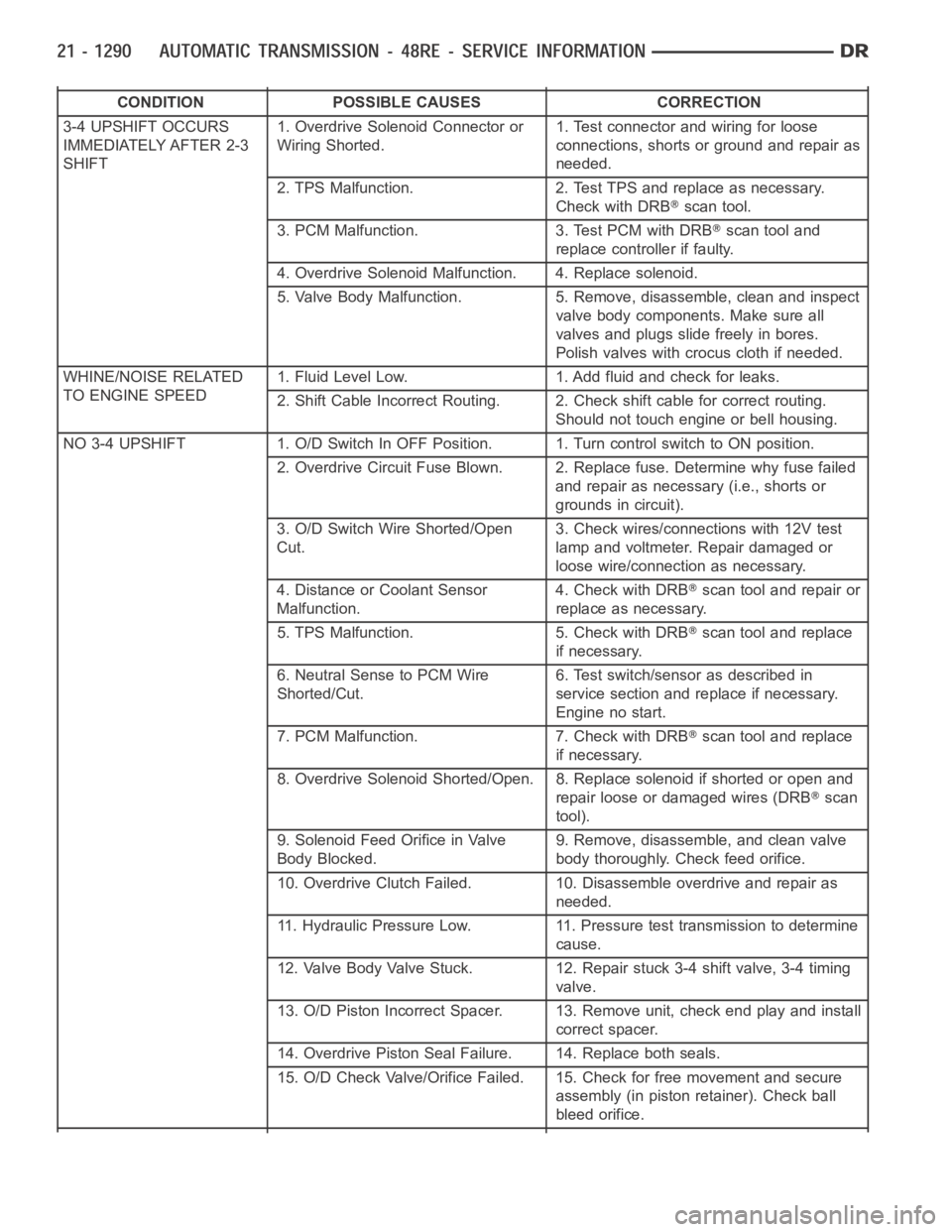
CONDITION POSSIBLE CAUSES CORRECTION
3-4 UPSHIFT OCCURS
IMMEDIATELY AFTER 2-3
SHIFT1. Overdrive Solenoid Connector or
Wiring Shorted.1. Test connector and wiring for loose
connections, shorts or ground and repair as
needed.
2. TPS Malfunction. 2. Test TPS and replace as necessary.
Check with DRB
scan tool.
3. PCM Malfunction. 3. Test PCM with DRB
scan tool and
replace controller if faulty.
4. Overdrive Solenoid Malfunction. 4. Replace solenoid.
5. Valve Body Malfunction. 5. Remove, disassemble, clean and inspect
valve body components. Make sure all
valves and plugs slide freely in bores.
Polish valves with crocus cloth if needed.
WHINE/NOISE RELATED
TO ENGINE SPEED1. Fluid Level Low. 1. Add fluid and check for leaks.
2. Shift Cable Incorrect Routing. 2. Check shift cable for correct routing.
Should not touch engine or bell housing.
NO3-4UPSHIFT 1.O/DSwitchInOFFPosition. 1.TurncontrolswitchtoONposition.
2. Overdrive Circuit Fuse Blown. 2. Replace fuse. Determine why fuse failed
and repair as necessary (i.e., shorts or
grounds in circuit).
3. O/D Switch Wire Shorted/Open
Cut.3. Check wires/connections with 12V test
lamp and voltmeter. Repair damaged or
loose wire/connection as necessary.
4. Distance or Coolant Sensor
Malfunction.4. Check with DRB
scan tool and repair or
replace as necessary.
5. TPS Malfunction. 5. Check with DRB
scan tool and replace
if necessary.
6. Neutral Sense to PCM Wire
Shorted/Cut.6. Test switch/sensor as described in
service section and replace if necessary.
Engine no start.
7. PCM Malfunction. 7. Check with DRB
scan tool and replace
if necessary.
8. Overdrive Solenoid Shorted/Open. 8. Replace solenoid if shorted or openand
repair loose or damaged wires (DRB
scan
tool).
9. Solenoid Feed Orifice in Valve
Body Blocked.9. Remove, disassemble, and clean valve
body thoroughly. Check feed orifice.
10. Overdrive Clutch Failed. 10. Disassemble overdrive and repair as
needed.
11. Hydraulic Pressure Low. 11. Pressure test transmission to determine
cause.
12. Valve Body Valve Stuck. 12. Repair stuck 3-4 shift valve, 3-4 timing
valve.
13. O/D Piston Incorrect Spacer. 13. Remove unit, check end play and install
correct spacer.
14. Overdrive Piston Seal Failure. 14. Replace both seals.
15. O/D Check Valve/Orifice Failed. 15. Check for free movement and secure
assembly (in piston retainer). Check ball
bleed orifice.
Page 3815 of 5267

REMOVAL
NOTE: The overdrive unit can be removed and serviced separately. It is not necessary to remove the entire
transmission assembly to perform overdrive unit repairs.
1. Disconnect battery negative cable.
2. Raise vehicle.
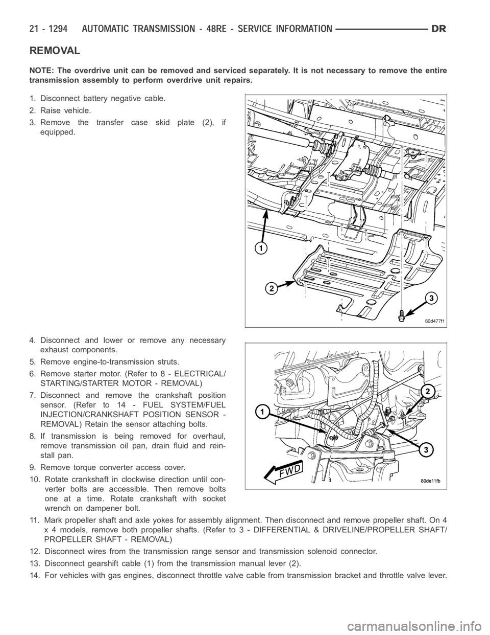
3. Remove the transfer case skid plate (2), if
equipped.
4. Disconnect and lower or remove any necessary
exhaust components.
5. Remove engine-to-transmission struts.
6. Remove starter motor. (Refer to 8 - ELECTRICAL/
STARTING/STARTER MOTOR - REMOVAL)
7. Disconnect and remove the crankshaft position
sensor. (Refer to 14 - FUEL SYSTEM/FUEL
INJECTION/CRANKSHAFT POSITION SENSOR -
REMOVAL) Retain the sensor attaching bolts.
8. If transmission is being removed for overhaul,
remove transmission oil pan, drain fluid and rein-
stall pan.
9. Remove torque converter access cover.
10. Rotate crankshaft in clockwise direction until con-
verter bolts are accessible. Then remove bolts
one at a time. Rotate crankshaft with socket
wrench on dampener bolt.
11. Mark propeller shaft and axle yokes for assembly alignment. Then disconnect and remove propeller shaft. On 4
x 4 models, remove both propeller shafts. (Refer to 3 - DIFFERENTIAL & DRIVELINE/PROPELLER SHAFT/
PROPELLER SHAFT - REMOVAL)
12. Disconnect wires from the transmission range sensor and transmissionsolenoid connector.
13. Disconnect gearshift cable (1) from the transmission manual lever (2).
14. For vehicles with gas engines, disconnect throttle valve cable from transmission bracket andthrottle valve lever.
Page 3816 of 5267
15. For vehicles with a diesel engine, remove the
bolts (2) holding the transmission throttle valve
actuator (TTVA) (1) to the transmission case.
16. Allow the TTVA (1) to rotate clockwise away from
the transmission.
17. Remove the wiring connector (2) from the TTVA
(1).
18. Lift the TTVA (1) straight upward and off the throt-
tle valve shaft (3).
Page 3817 of 5267
19. On 4X4 models, disconnect shift rod from transfer
case shift lever.
20. Support rear of engine with safety stand or jack.
21. Raise transmission slightly with service jack to
relieve load on crossmember and supports.
22. Remove the nuts (3) securing rear support (1) to
the transmission crossmember.
23. Remove the bolts(2) holding the rear support (1)
to the transmission (5) remove the rear support.
24. Remove bolts attaching crossmember to frame
and remove crossmember.
25. On 4X4 models, remove transfer case. (Refer to
21 - TRANSMISSION AND TRANSFER CASE/
TRANSFER CASE - REMOVAL)
26. Remove fill tube (7) bracket bolts and pull tube
out of transmission. Retain fill tube seal (6). On
4X4 models, it will also be necessary to remove
bolt attaching transfer case vent tube to converter
housing.
27. Disconnect fluid cooler lines (6, 7) at transmission
(5), diesel engines.
Page 3818 of 5267
28. Disconnect fluid cooler lines (4, 5) at transmission
(3), gas engines.
29. Remove all bolts (1) holding the transmission (3)
to the engine adapter (2), diesel engines.
30. Carefully work transmission and torque converter
assembly rearward off engine block dowels.
31. Lower transmission and remove assembly from
under the vehicle.
32. To remove torque converter, remove C-clamp
from edge of bell housing and carefully slide
torque converter out of the transmission.
Page 3819 of 5267

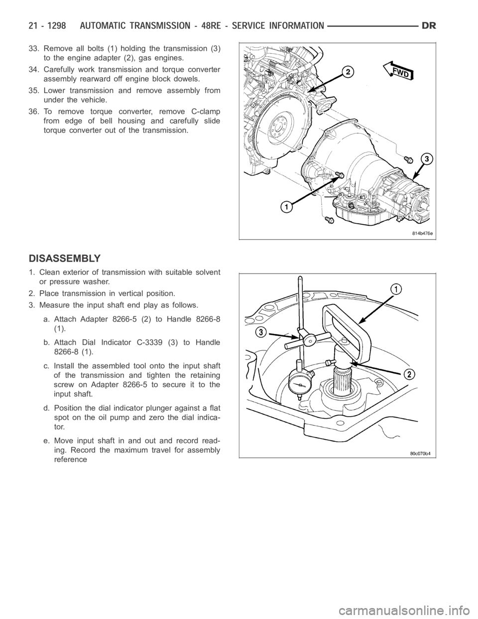
33. Remove all bolts (1) holding the transmission (3)
to the engine adapter (2), gas engines.
34. Carefully work transmission and torque converter
assembly rearward off engine block dowels.
35. Lower transmission and remove assembly from
under the vehicle.
36. To remove torque converter, remove C-clamp
from edge of bell housing and carefully slide
torque converter out of the transmission.
DISASSEMBLY
1. Clean exterior of transmission with suitable solvent
or pressure washer.
2. Place transmission in vertical position.
3. Measure the input shaft end play as follows.
a. Attach Adapter 8266-5 (2) to Handle 8266-8
(1).
b. Attach Dial Indicator C-3339 (3) to Handle
8266-8 (1).
c. Install the assembled tool onto the input shaft
of the transmission and tighten the retaining
screw on Adapter 8266-5 to secure it to the
input shaft.
d. Position the dial indicator plunger against a flat
spot on the oil pump and zero the dial indica-
tor.
e. Move input shaft in and out and record read-
ing. Record the maximum travel for assembly
reference
Page 3821 of 5267
11. Remove accumulator outer spring (2) (diesel
engines only), piston (1), and inner spring (3)
(V-10 engine only). Note position of piston and
springs for assembly reference. Remove and dis-
card piston seals if worn or cut.
12. Remove pump oil seal with suitable pry tool or
slide-hammer mounted screw.
13. Remove front band lever pin access plug (1). Use
square end of 1/4 in. drive extension (2) to
remove plug as shown.
14. Begin removal of the oil pump and reaction shaft
support assembly by tightening the front band
adjusting screw (2) until band is tight around front
clutch retainer. This will prevent retainer from
coming out with pump and possibly damaging
clutch or pump components.
Page 3836 of 5267

ACCUMULATOR, VALVE BODY, OIL PAN, AND TORQUE CONVERTER
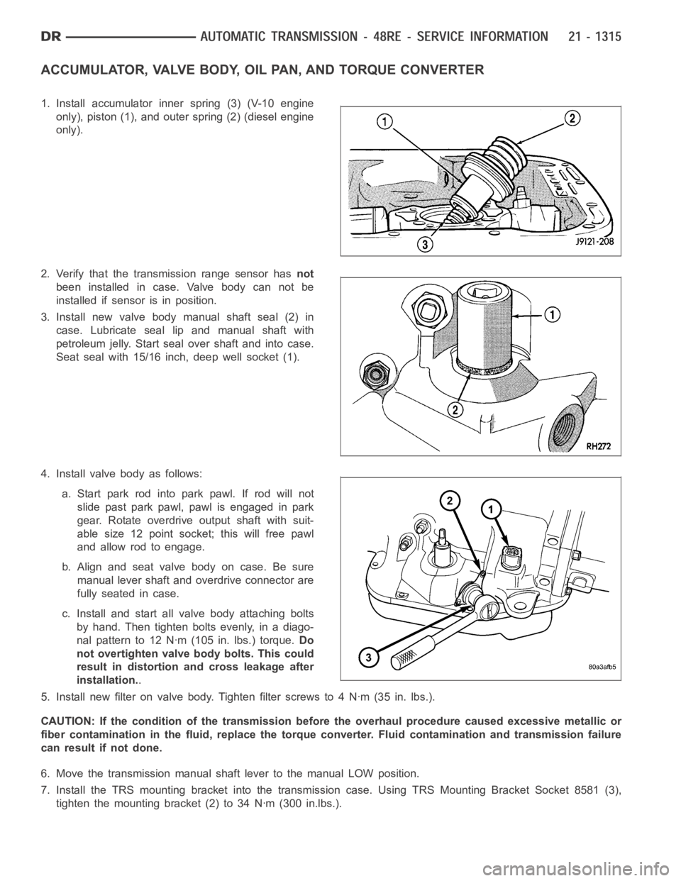
1. Install accumulator inner spring (3) (V-10 engine
only), piston (1), and outer spring (2) (diesel engine
only).
2. Verify that the transmission range sensor hasnot
been installed in case. Valve body can not be
installed if sensor is in position.
3. Install new valve body manual shaft seal (2) in
case. Lubricate seal lip and manual shaft with
petroleum jelly. Start seal over shaft and into case.
Seat seal with 15/16 inch, deep well socket (1).
4. Install valve body as follows:
a. Start park rod into park pawl. If rod will not
slide past park pawl, pawl is engaged in park
gear. Rotate overdrive output shaft with suit-
able size 12 point socket; this will free pawl
and allow rod to engage.
b.Alignandseatvalvebodyoncase.Besure
manual lever shaft and overdrive connector are
fully seated in case.
c. Install and start all valve body attaching bolts
by hand. Then tighten bolts evenly, in a diago-
nal pattern to 12 Nꞏm (105 in. lbs.) torque.Do
not overtighten valve body bolts. This could
result in distortion and cross leakage after
installation..
5. Install new filter on valve body. Tighten filter screws to 4 Nꞏm (35 in. lbs.).
CAUTION: If the condition of the transmission before the overhaul procedure caused excessive metallic or
fiber contamination in the fluid, replace the torque converter. Fluid contamination and transmission failure
can result if not done.
6. Move the transmission manual shaft lever to the manual LOW position.
7. Install the TRS mounting bracket into the transmission case. Using TRS Mounting Bracket Socket 8581 (3),
tighten the mounting bracket (2) to 34 Nꞏm (300 in.lbs.).