2006 DODGE RAM SRT-10 engine
[x] Cancel search: enginePage 2907 of 5267
When Monitored:
Every 7 msec with:
1) Engine speed greater than 500 RPM.
2) Battery voltage between 10 and 16 volts.
Set Condition:
CAN C BUS messages are not received for 10 seconds.
Theory of Operation
The NGC controller communicates over the CAN C BUS. The transmission controller continuously monitors BUS
activity. The CAN C BUS is also used to communicate transmission MIL statusto the Engine Controller. If the
Engine Controller is unable to communicate with the Transmission Controller, a DTC will set and the Engine Con-
troller will illuminate the MIL.
Refer to 8-ELECTRICAL/ELECTRONIC CONTROL MODULES - DIAGNOSIS AND TESTING for diagnostic pro-
cedures and for further possible causes.
Page 2908 of 5267
STANDARD PROCEDURE
PRE-DIAGNOSTIC TROUBLESHOOTING PROCEDURE - 42RLE
For a complete wiring diagramRefer to Section 8W.
1.
Perform the following steps prior to any diagnostic procedure:
Many transmission symptoms can be caused by a low fluid level. If the fluid level is low, locate and repair any
leaks and fill the transmission to the proper fluid level. Refer to the Service Information for the proper repair
and fluid fill procedures.
Testing should only be performed with the battery fully charged to avoid false diagnosis.
With the scan tool, read Engine (PCM) DTCs. If Engine DTCs are present, refer to the Driveability Category
and perform to the appropriate diagnostic procedure(s) before proceeding.
With the scan tool, read Transmission (TCM) DTCs. Record all Stored, Active, and Pending DTC information.
Diagnose any Pending DTC as a matured DTC.
With the scan tool, read DTC EVENT DATA.Use this data to identify the conditions in which the DTC was set.
Note: Performing a Battery Disconnect will clear all DTC EVENT DATA and reset all learned Transmis-
sion values to the controllers default values, which may temporarily result in erratic shift schedules.
With the scan tool, perform the Shift Lever Position Test. If the test does not pass, refer to the diagnostic
procedure for P0706-Check Shifter Signal.
For Gear Ratio Error DTCs, use the scan tool to read and record the Clutch Volume Index (CVI) information.
Use the wiring diagram as a guide, inspect the wiring and connectors related to this circuit and repair as nec-
essary.
Refer to the When Monitored and Set Conditions for this DTC. DTCs can set at ignition on, at start up, driving
under specific conditions, and after controller diagnostic monitors haverun.
Refer to applicable Technical Service Bulletins (TSBs) for controller software update information. Some condi-
tions can be corrected by upgrading the Engine (PCM) or Transmission (TCM)controller software.
Check for any Service Information Tune-ups or Service Bulletins for any possible causes that may apply.
Were there any repairs made that fixed the vehicle?
Ye s>>
Testing complete.
Perform 42RLE VERIFICATION TEST - VER1(Referto21-TRANSMISSION/TRANSAXLE/AUTO-
MATIC - 42RLE - STANDARD PROCEDURE)
No>>
Refer to the Transmission category and perform the appropriate diagnostic procedure(s). (Refer to 21 -
TRANSMISSION/TRANSAXLE/AUTOMATIC - 42RLE - DIAGNOSIS AND TESTING)
Page 2909 of 5267
42RLE TRANSMISSION VERIFICATION TEST - VER 1
1.
Perform the following after completion of a diagnostic repair:
Note: After completion of the Transmission Verification Test, the Powertrain Verification Test must be
performed. Refer to the Engine Category.
Reconnect any disconnected components.
With the scan tool, erase all Transmission and Engine DTCs.
Erase DTC P0700 under engine to turn off the MIL off after completion of transmission repairs.
Perform *PRNDL FAULT CLEARING PROCEDURE after completion of repairs for P0706-TRANSMISSION
RANGE SENSOR RATIONALITY.
If the Powertrain Control Module or the Transmission has been repaired or replaced, it is necessary to perform
the scan tool Quick Learn Procedure.
If the Torque converter has been replaced, with the scan tool perform TCC BREAK-IN.
If the Powertrain Control Module or Front Control Module has been replacedyoumustresetthePinionFactor
in the Front Control Module.
With the scan tool, display Transmission Temperature. Start and run the engine until the Transmission Tem-
perature is HOT, above 43° C or 110° F.
Check the transmission fluid and adjust if necessary. Refer to the ServiceInformation for the Fluid Fill proce-
dure.
Road test the vehicle. With the scan tool, monitor the engine RPM. Make 15 to20 1-2, 2-3, 3-4 upshifts.
Perform these shifts from a standing start to 45 mph with a constant throttleopeningof20to25degrees.
With speeds below 25 MPH, make 5 to 8 wide open throttle kickdowns to 1st gear. Allow at least 5 seconds
each in 2nd and 3rd gear between each kickdown.
For a specific DTC, drive the vehicle to the Symptom’s When Monitored/WhenSet conditions to verify the DTC
is repaired.
If equipped with AutoStick, upshift and downshift several times using the AutoStickfeature during the road
test.
Note: Use the OBDII task manager to run a Good Trip in each gear, this will confirm the repair and to
ensure that the DTC has not re-matured.
Check for any Diagnostic Trouble Codes (DTCs) during and after the road test.
Did any Diagnostic Trouble Codes set during the road test?
Ye s>>
Repair is not complete. Refer to the Transmission category and perform theappropriate symptom(s).
(Refer to 21 - TRANSMISSION/TRANSAXLE/AUTOMATIC - 42RLE - DIAGNOSIS AND TESTING)
No>>
Repair is complete.
Page 2918 of 5267
FOURTHGEARPOWERFLOW
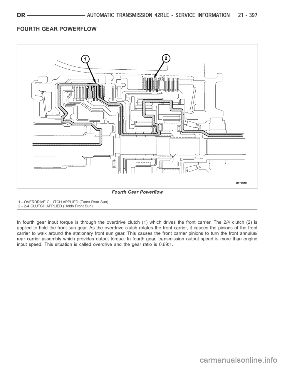
In fourth gear input torque is through the overdrive clutch (1) which drives the front carrier. The 2/4 clutch (2) is
applied to hold the front sun gear. As the overdrive clutch rotates the front carrier, it causes the pinions of the front
carrier to walk around the stationary front sun gear. This causes the frontcarrier pinions to turn the front annulus/
rear carrier assembly which provides output torque. In fourth gear, transmission output speed is more than engine
input speed. This situation is called overdrive and the gear ratio is 0.69:1.
Fourth Gear Powerflow
1 - OVERDRIVE CLUTCH APPLIED (Turns Rear Sun)
2 - 2-4 CLUTCH APPLIED (Holds Front Sun)
Page 2919 of 5267
REVERSE GEAR POWERFLOW
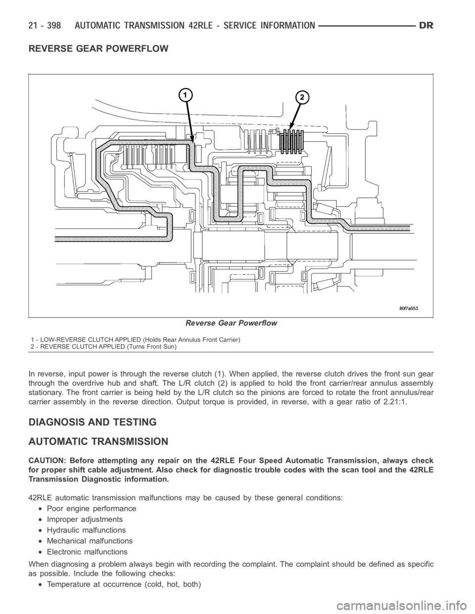
In reverse, input power is through the reverse clutch (1). When applied, the reverse clutch drives the front sun gear
through the overdrive hub and shaft. The L/R clutch (2) is applied to hold the front carrier/rear annulus assembly
stationary. The front carrier is being held by the L/R clutch so the pinionsare forced to rotate the front annulus/rear
carrier assembly in the reverse direction. Output torque is provided, in reverse, with a gear ratio of 2.21:1.
DIAGNOSIS AND TESTING
AUTOMATIC TRANSMISSION
CAUTION: Before attempting any repair on the 42RLE Four Speed Automatic Transmission, always check
for proper shift cable adjustment. Also check for diagnostic trouble codes with the scan tool and the 42RLE
Transmission Diagnostic information.
42RLE automatic transmission malfunctions may be caused by these generalconditions:
Poor engine performance
Improper adjustments
Hydraulic malfunctions
Mechanical malfunctions
Electronic malfunctions
When diagnosing a problem always begin with recording the complaint. The complaint should be defined as specific
as possible. Includethe following checks:
Temperature at occurrence (cold, hot, both)
Reverse Gear Powerflow
1 - LOW-REVERSE CLUTCH APPLIED (Holds Rear Annulus Front Carrier)
2 - REVERSE CLUTCH APPLIED (Turns Front Sun)
Page 2921 of 5267
HYDRAULIC PRESSURE TESTS
Pressure testing is a very important step in the diag-
nostic procedure. These tests usually reveal the cause
of most transmission problems.
Before performing pressure tests, be certain that fluid
level and condition, and shift cable adjustments have
been checked and approved. Fluid must be at operat-
ing temperature (150 to 200 degrees F.).
Install an engine tachometer, raise vehicle on hoist
which allows the wheels to turn, and position tachom-
eter so it can be read.
Using special adapters L-4559, attach 300 psi
gauge(s) C-3293SP to the port(s) required for test
being conducted.
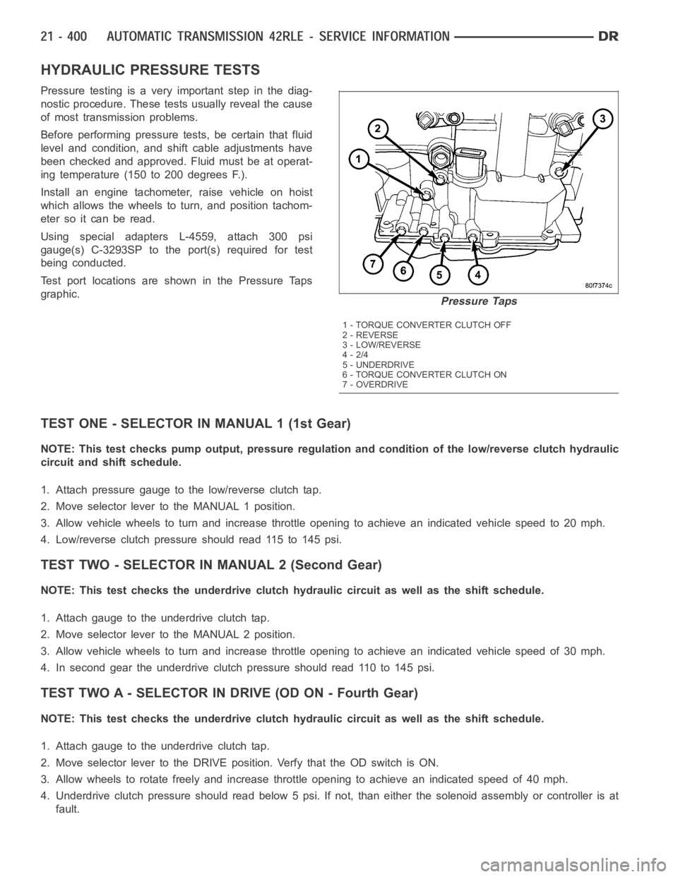
Test port locations are shown in the Pressure Taps
graphic.
TEST ONE - SELECTOR IN MANUAL 1 (1st Gear)
NOTE: This test checks pump output, pressure regulation and condition of the low/reverse clutch hydraulic
circuit and shift schedule.
1. Attach pressure gauge to the low/reverse clutch tap.
2. Move selector lever to the MANUAL 1 position.
3. Allow vehicle wheels to turn and increase throttle opening to achieve anindicatedvehiclespeedto20mph.
4. Low/reverse clutch pressure should read 115 to 145 psi.
TEST TWO - SELECTOR IN MANUAL 2 (Second Gear)
NOTE: This test checks the underdrive clutch hydraulic circuit as well as the shift schedule.
1. Attach gauge to the underdrive clutch tap.
2. Move selector lever to the MANUAL 2 position.
3. Allow vehicle wheels to turn and increase throttle opening to achieve anindicated vehicle speed of 30 mph.
4. In second gear the underdrive clutch pressure should read 110 to 145 psi.
TEST TWO A - SELECTOR IN DRIVE (OD ON - Fourth Gear)
NOTE: This test checks the underdrive clutch hydraulic circuit as well as the shift schedule.
1. Attach gauge to the underdrive clutch tap.
2. Move selector lever to the DRIVE position. Verfy that the OD switch is ON.
3. Allow wheels to rotate freely and increase throttle opening to achieve an indicated speed of 40 mph.
4. Underdrive clutch pressure should read below 5 psi. If not, than either the solenoid assembly or controller is at
fault.
Pressure Taps
1 - TORQUE CONVERTER CLUTCH OFF
2 - REVERSE
3 - LOW/REVERSE
4-2/4
5 - UNDERDRIVE
6 - TORQUE CONVERTER CLUTCH ON
7-OVERDRIVE
Page 2923 of 5267
5. Iftheunderdriveclutchpressureisgreaterthan5psiinStep4ofTestTwo-A, a defective solenoid/pressure
switch assembly or controller is the cause.
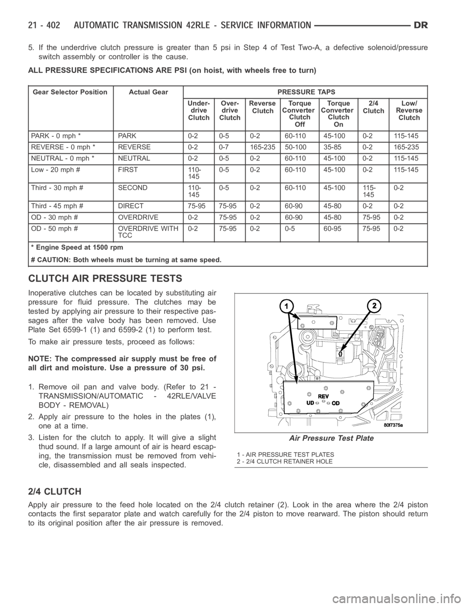
ALL PRESSURE SPECIFICATIONS ARE PSI (on hoist, with wheels free to turn)
Gear Selector Position Actual Gear PRESSURE TAPS
Under-
drive
ClutchOver-
drive
ClutchReverse
ClutchTo r q u e
Converter
Clutch
OffTo r q u e
Converter
Clutch
On2/4
ClutchLow/
Reverse
Clutch
PARK - 0 mph * PARK 0-2 0-5 0-2 60-110 45-100 0-2 115-145
REVERSE - 0 mph * REVERSE 0-2 0-7 165-235 50-100 35-85 0-2 165-235
NEUTRAL - 0 mph * NEUTRAL 0-2 0-5 0-2 60-110 45-100 0-2 115-145
Low - 20 mph # FIRST 110-
1450-5 0-2 60-110 45-100 0-2 115-145
Third-30mph# SECOND 110-
1450-5 0-2 60-110 45-100 115-
1450-2
Third - 45 mph # DIRECT 75-95 75-95 0-2 60-90 45-80 0-2 0-2
OD - 30 mph # OVERDRIVE 0-2 75-95 0-2 60-90 45-80 75-95 0-2
OD - 50 mph # OVERDRIVE WITH
TCC0-2 75-95 0-2 0-5 60-95 75-95 0-2
* Engine Speed at 1500 rpm
# CAUTION: Both wheels must be turning at same speed.
CLUTCH AIR PRESSURE TESTS
Inoperative clutches can be located by substituting air
pressure for fluid pressure. The clutches may be
tested by applying air pressure to their respective pas-
sages after the valve body has been removed. Use
Plate Set 6599-1 (1) and 6599-2 (1) to perform test.
To make air pressure tests, proceed as follows:
NOTE: The compressed air supply must be free of
all dirt and moisture. Use a pressure of 30 psi.
1. Remove oil pan and valve body. (Refer to 21 -
TRANSMISSION/AUTOMATIC - 42RLE/VALVE
BODY - REMOVAL)
2. Apply air pressure to the holes in the plates (1),
one at a time.
3. Listen for the clutch to apply. It will give a slight
thud sound. If a large amount of air is heard escap-
ing, the transmission must be removed from vehi-
cle, disassembled and all seals inspected.
2/4 CLUTCH
Apply air pressure to the feed hole located on the 2/4 clutch retainer (2). Look in the area where the 2/4 piston
contacts the first separator plate and watch carefully for the 2/4 piston tomoverearward.Thepistonshouldreturn
to its original position after the air pressure is removed.
Air Pressure Test Plate
1 - AIR PRESSURE TEST PLATES
2 - 2/4 CLUTCH RETAINER HOLE
Page 2924 of 5267
OVERDRIVE CLUTCH
Apply air pressure to the overdrive clutch apply passage and watch for the push/pull piston to move forward. The
piston should return to its starting position when the air pressure is removed.
REVERSE CLUTCH
Apply air pressure to the reverse clutch apply passage and watch for the push/pull piston to move rearward. The
piston should return to its starting position when the air pressure is removed.
LOW/REVERSE CLUTCH
Apply air pressure to the low/reverse clutch feed hole passage. Look in thearea where the low/reverse piston con-
tacts the first separator plate. Watch carefully for the piston to move forward. The piston should return to its original
position after the air pressure is removed.
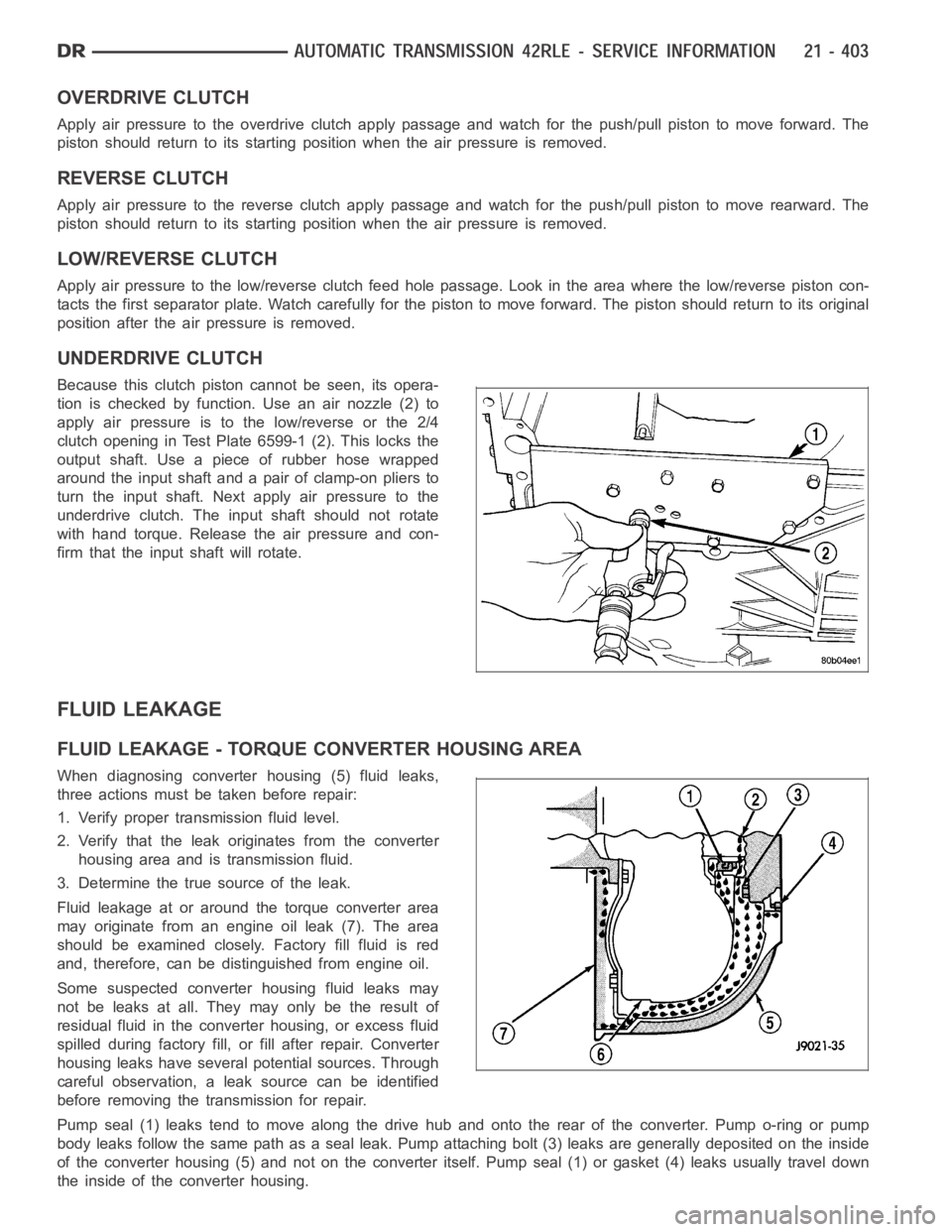
UNDERDRIVE CLUTCH
Because this clutch piston cannot be seen, its opera-
tion is checked by function. Use an air nozzle (2) to
apply air pressure is to the low/reverse or the 2/4
clutch opening in Test Plate 6599-1 (2). This locks the
output shaft. Use a piece of rubber hose wrapped
around the input shaft and a pair of clamp-on pliers to
turn the input shaft. Next apply air pressure to the
underdrive clutch. The input shaft should not rotate
with hand torque. Release the air pressure and con-
firm that the input shaft will rotate.
FLUID LEAKAGE
FLUID LEAKAGE - TORQUE CONVERTER HOUSING AREA
When diagnosing converter housing (5) fluid leaks,
three actions must be taken before repair:
1. Verify proper transmission fluid level.
2. Verify that the leak originates from the converter
housing area and is transmission fluid.
3. Determine the true source of the leak.
Fluid leakage at or around the torque converter area
may originate from an engine oil leak (7). The area
should be examined closely. Factory fill fluid is red
and, therefore, can be distinguished from engine oil.
Some suspected converter housing fluid leaks may
not be leaks at all. They may only be the result of
residual fluid in the converter housing, or excess fluid
spilled during factory fill, or fill after repair. Converter
housing leaks have several potential sources. Through
careful observation, a leak source can be identified
before removing the transmission for repair.
Pump seal (1) leaks tend to move along the drive hub and onto the rear of the converter. Pump o-ring or pump
body leaks follow the same path as a seal leak. Pump attaching bolt (3) leaksare generally deposited on the inside
of the converter housing (5) and not on the converter itself. Pump seal (1) or gasket (4) leaks usually travel down
the inside of the converter housing.