Page 3017 of 5267
CABLE-GEARSHIFT
DIAGNOSIS AND TESTING - GEARSHIFT CABLE
1. Engine starts must be possible with shift lever in PARK or NEUTRAL positions only. Engine starts must not be
possible in any other gear position.
2. With the shift lever in the:
a. PARK position - Apply upward force on the shift arm and remove pressure. Engine starts must be possible.
b. PARK position - Apply downward force on the shift arm and remove pressure. Engine starts must be pos-
sible.
c. NEUTRAL position - Normal position. Engine starts must be possible.
d. NEUTRAL position - Engine running and brakes applied, apply upward forceontheshiftarm.Transmission
shall not be able to shift from neutral to reverse.
REMOVAL
1. Shift transmission into PARK.
2. Raise vehicle.
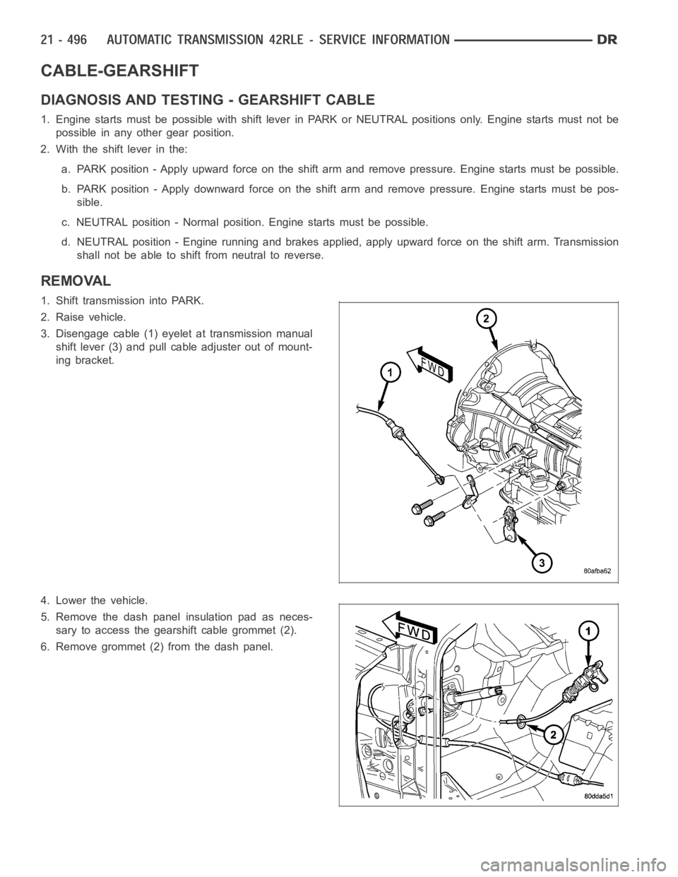
3. Disengage cable (1) eyelet at transmission manual
shift lever (3) and pull cable adjuster out of mount-
ing bracket.
4. Lower the vehicle.
5. Remove the dash panel insulation pad as neces-
sary to access the gearshift cable grommet (2).
6. Remove grommet (2) from the dash panel.
Page 3019 of 5267
ADJUSTMENTS - GEARSHIFT CABLE
Check adjustment by starting the engine in PARK and NEUTRAL. Adjustment isCORRECT if the engine starts only
in these positions. Adjustment is INCORRECT if the engine starts in one butnot both positions. If the engine starts
in any position other than PARK or NEUTRAL, or if the engine will not start atall, the transmission range sensor
may be faulty.
Gearshift Adjustment Procedure
1. Shift transmission into PARK.
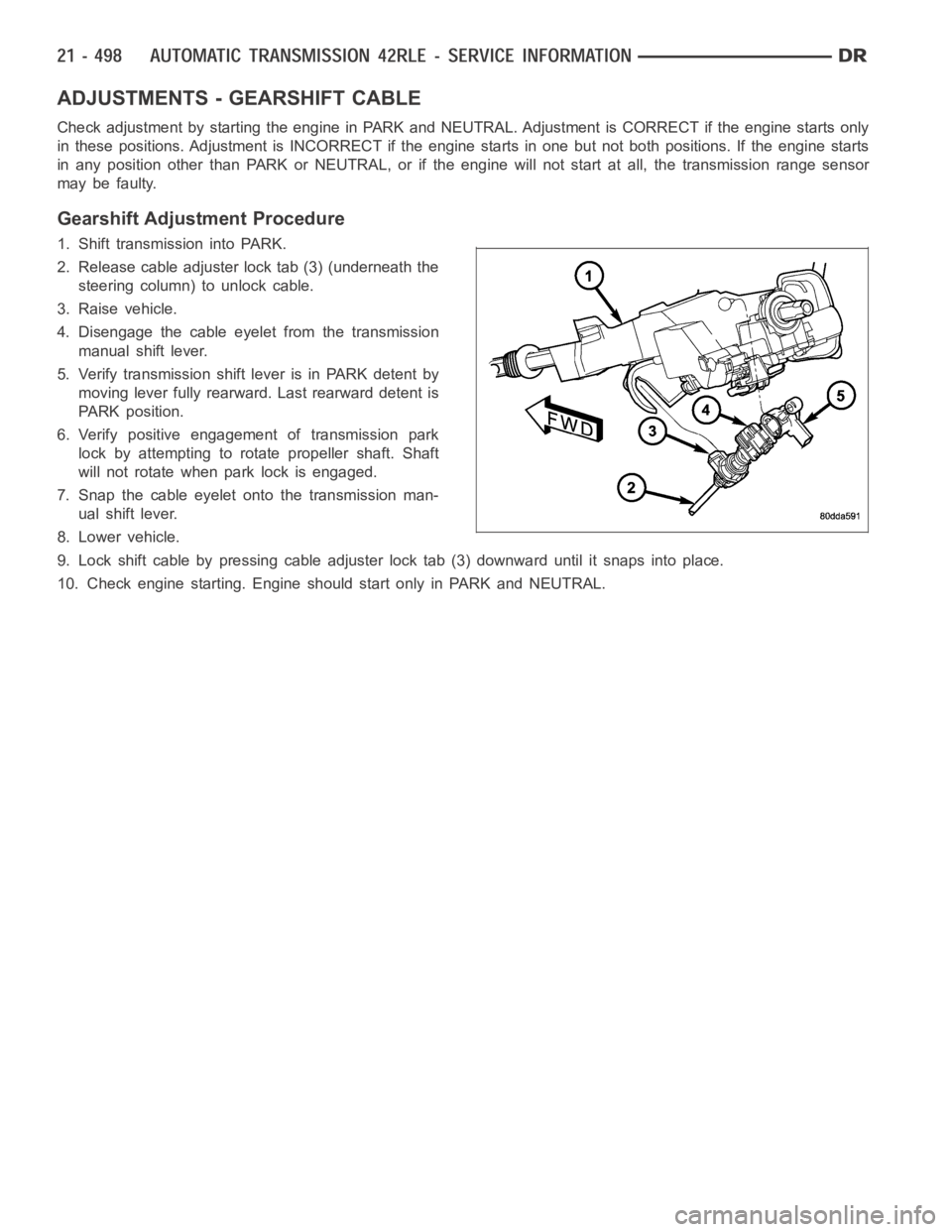
2. Release cable adjuster lock tab (3) (underneath the
steering column) to unlock cable.
3. Raise vehicle.
4. Disengage the cable eyelet from the transmission
manual shift lever.
5. Verify transmission shift lever is in PARK detent by
moving lever fully rearward. Last rearward detent is
PARK position.
6. Verify positive engagement of transmission park
lock by attempting to rotate propeller shaft. Shaft
will not rotate when park lock is engaged.
7. Snap the cable eyelet onto the transmission man-
ual shift lever.
8. Lower vehicle.
9. Lock shift cable by pressing cable adjuster lock tab (3) downward until it snaps into place.
10. Check engine starting. Engine should start only in PARK and NEUTRAL.
Page 3044 of 5267
SENSOR-INPUT SPEED
DESCRIPTION
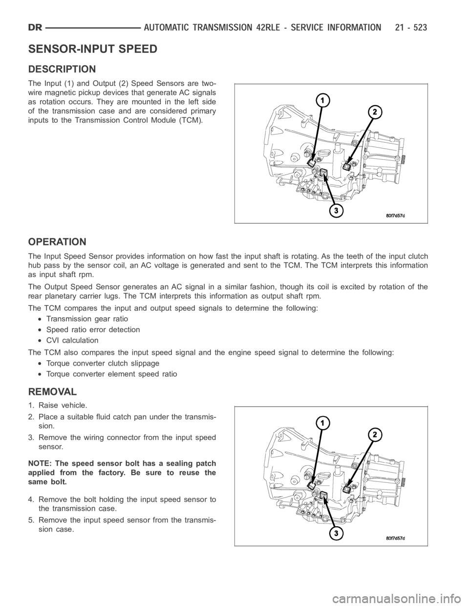
The Input (1) and Output (2) Speed Sensors are two-
wire magnetic pickup devices that generate AC signals
as rotation occurs. They are mounted in the left side
of the transmission case and are considered primary
inputs to the Transmission Control Module (TCM).
OPERATION
The Input Speed Sensor provides information on how fast the input shaft is rotating. As the teeth of the input clutch
hub pass by the sensor coil, an AC voltage is generated and sent to the TCM. The TCM interprets this information
as input shaft rpm.
The Output Speed Sensor generates an AC signal in a similar fashion, thoughitscoilisexcitedbyrotationofthe
rear planetary carrier lugs. The TCM interprets this information as outputshaftrpm.
The TCM compares the input and output speed signals to determine the following:
Transmission gear ratio
Speed ratio error detection
CVI calculation
The TCM also compares the input speed signal and the engine speed signal to determine the following:
Torque converter clutch slippage
Torque converter element speed ratio
REMOVAL
1. Raise vehicle.
2. Place a suitable fluid catch pan under the transmis-
sion.
3. Remove the wiring connector from the input speed
sensor.
NOTE: The speed sensor bolt has a sealing patch
applied from the factory. Be sure to reuse the
same bolt.
4. Remove the bolt holding the input speed sensor to
the transmission case.
5. Remove the input speed sensor from the transmis-
sion case.
Page 3046 of 5267
SENSOR-VARIABLE LINE PRESSURE
DESCRIPTION
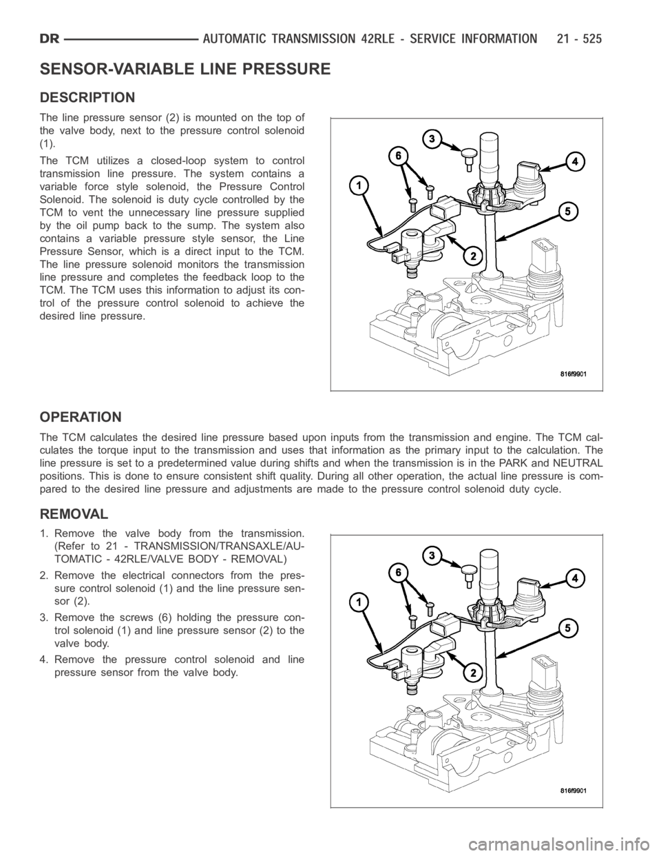
The line pressure sensor (2) is mounted on the top of
the valve body, next to the pressure control solenoid
(1).
The TCM utilizes a closed-loop system to control
transmission line pressure. The system contains a
variable force style solenoid, the Pressure Control
Solenoid. The solenoid is duty cycle controlled by the
TCM to vent the unnecessary line pressure supplied
by the oil pump back to the sump. The system also
contains a variable pressure style sensor, the Line
Pressure Sensor, which is a direct input to the TCM.
The line pressure solenoid monitors the transmission
line pressure and completes the feedback loop to the
TCM. The TCM uses this information to adjust its con-
trol of the pressure control solenoid to achieve the
desired line pressure.
OPERATION
The TCM calculates the desired line pressure based upon inputs from the transmission and engine. The TCM cal-
culates the torque input to the transmission and uses that information as the primary input to the calculation. The
line pressure is set to a predetermined value during shifts and when the transmission is in the PARK and NEUTRAL
positions. This is done to ensure consistent shift quality. During all other operation, the actual line pressure is com-
pared to the desired line pressure and adjustments are made to the pressurecontrol solenoid duty cycle.
REMOVAL
1. Remove the valve body from the transmission.
(Refer to 21 - TRANSMISSION/TRANSAXLE/AU-
TOMATIC - 42RLE/VALVE BODY - REMOVAL)
2. Remove the electrical connectors from the pres-
sure control solenoid (1) and the line pressure sen-
sor (2).
3. Remove the screws (6) holding the pressure con-
trol solenoid (1) and line pressure sensor (2) to the
valve body.
4. Remove the pressure control solenoid and line
pressure sensor from the valve body.
Page 3051 of 5267
SENSOR-OUTPUT SPEED
DESCRIPTION
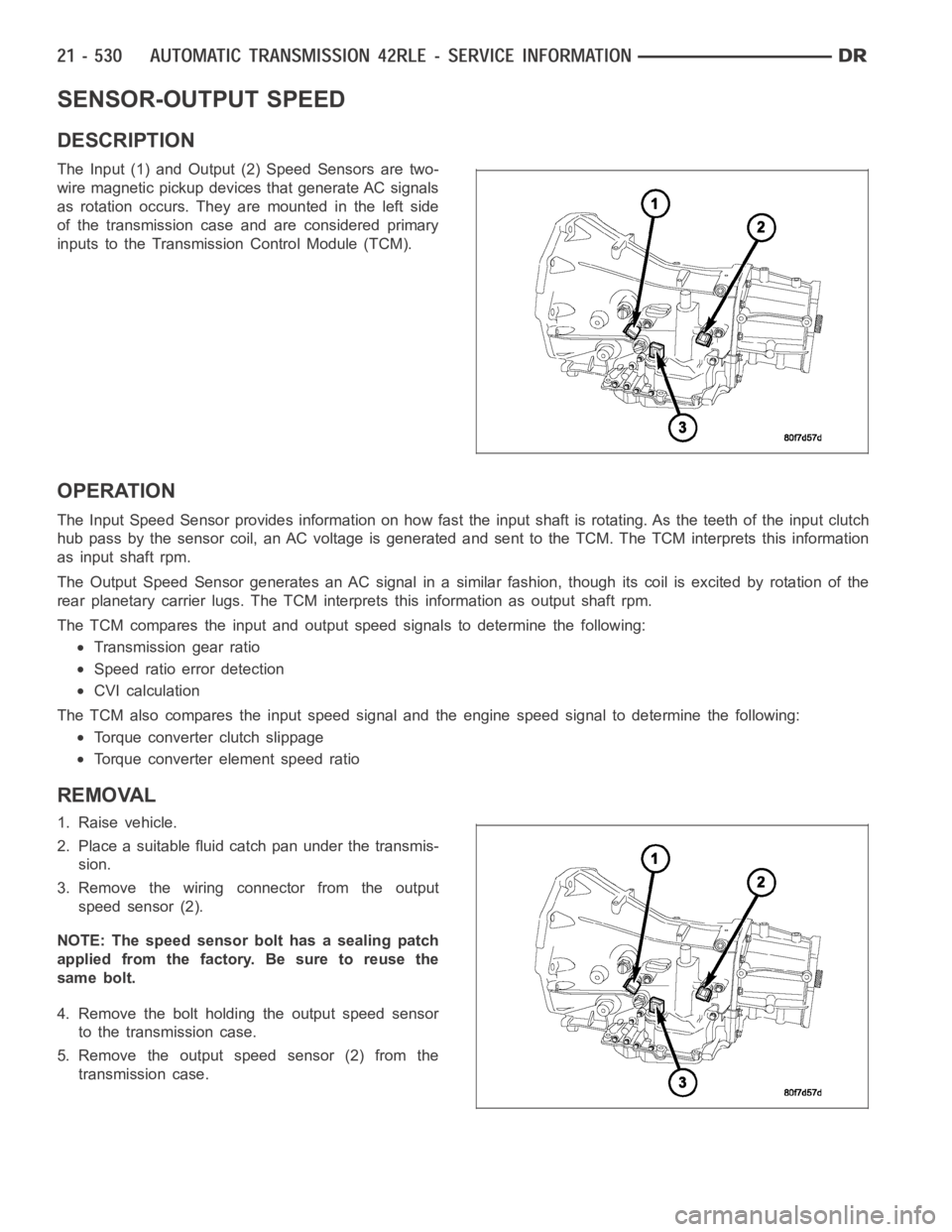
The Input (1) and Output (2) Speed Sensors are two-
wire magnetic pickup devices that generate AC signals
as rotation occurs. They are mounted in the left side
of the transmission case and are considered primary
inputs to the Transmission Control Module (TCM).
OPERATION
The Input Speed Sensor provides information on how fast the input shaft is rotating. As the teeth of the input clutch
hub pass by the sensor coil, an AC voltage is generated and sent to the TCM. The TCM interprets this information
as input shaft rpm.
The Output Speed Sensor generates an AC signal in a similar fashion, thoughitscoilisexcitedbyrotationofthe
rear planetary carrier lugs. The TCM interprets this information as outputshaftrpm.
The TCM compares the input and output speed signals to determine the following:
Transmission gear ratio
Speed ratio error detection
CVI calculation
The TCM also compares the input speed signal and the engine speed signal to determine the following:
Torque converter clutch slippage
Torque converter element speed ratio
REMOVAL
1. Raise vehicle.
2. Place a suitable fluid catch pan under the transmis-
sion.
3. Remove the wiring connector from the output
speed sensor (2).
NOTE: The speed sensor bolt has a sealing patch
applied from the factory. Be sure to reuse the
same bolt.
4. Remove the bolt holding the output speed sensor
to the transmission case.
5. Remove the output speed sensor (2) from the
transmission case.
Page 3054 of 5267
SEAL-OIL PUMP
REMOVAL
1. Remove the transmission from the vehicle (Refer to 21 - TRANSMISSION/AUTOMATIC - 42RLE - REMOVAL).
2. Remove the torque converter from the transmission bellhousing.
3. Use a screw mounted in a slide hammer to remove oil pump seal.
INSTALLATION
1. Clean and inspect oil pump seal seat. Then install seal using Seal Installer C-4193-A.
2. Clean and inspect torque converter hub. If nicks, scratches or hub wear are found, torque converter replacement
will be required.
CAUTION: If the torque converter isbeing replaced, apply a light coating of grease to the crankshaft pilot
hole. Also inspect the engine drive plate for cracks. If any cracks are found replace the drive plate. Do not
attempt to repair a cracked drive plate. Always use new torque converter todrive plate bolts.
3. Apply a light film of transmission oil to the torque converter hub and oilseal lips. Then install torque converter
into transmission. Be sure that the hub lugs mesh with the front pump lugs when installing.
4. Reinstall the transmission into the vehicle. (Refer to 21 - TRANSMISSION/TRANSAXLE/AUTOMATIC - 42RLE -
INSTALLATION)
Page 3061 of 5267
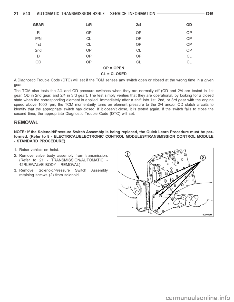
GEAR L/R 2/4 OD
ROPOPOP
P/N CL OP OP
1st CL OP OP
2nd OP CL OP
DOPOPCL
OD OP CL CL
OP = OPEN
CL = CLOSED
A Diagnostic Trouble Code (DTC) will set if the TCM senses any switch open orclosed at the wrong time in a given
gear.
The TCM also tests the 2/4 and OD pressure switches when they are normally off (OD and 2/4 are tested in 1st
gear, OD in 2nd gear, and 2/4 in 3rd gear). The test simply verifies that theyare operational, by looking for a closed
state when the corresponding elementis applied. Immediately after a shift into 1st, 2nd, or 3rd gear with the engine
speed above 1000 rpm, the TCM momentarily turns on element pressure to the 2/4 and/or OD clutch circuits to
identify that the appropriate switch has closed. If it doesn’t close, it istested again. If the switch fails to close the
second time, the appropriate Diagnostic Trouble Code (DTC) will set.
REMOVAL
NOTE: If the Solenoid/Pressure Switch Assembly is being replaced, the Quick Learn Procedure must be per-
formed. (Refer to 8 - ELECTRICAL/ELECTRONIC CONTROL MODULES/TRANSMISSION CONTROL MODULE
- STANDARD PROCEDURE)
1. Raise vehicle on hoist.
2. Remove valve body assembly from transmission.
(Refer to 21 - TRANSMISSION/AUTOMATIC -
42RLE/VALVE BODY - REMOVAL)
3. Remove Solenoid/Pressure Switch Assembly
retaining screws (2) from solenoid.
Page 3063 of 5267
CONVERTER-TORQUE
DESCRIPTION
The torque converter is a hydraulic device that cou-
ples the engine crankshaft to the transmission. The
torque converter consists of an outer shell with an
internal turbine (1), a stator (4), an overrunning clutch,
an impeller (2) and an electronically applied converter
clutch (6). The converterclutch provides reduced
engine speed and greater fuel economy when
engaged. Clutch engagement also provides reduced
transmission fluid temperatures. The torque converter
hub drives the transmission oil (fluid) pump.
The torque converter is a sealed, welded unit that is
not repairable and is serviced as an assembly.
CAUTION: The torque converter must be replaced
if a transmission failure resulted in large amounts
of metal or fiber contamination in the fluid.