2006 DODGE RAM SRT-10 engine
[x] Cancel search: enginePage 3064 of 5267
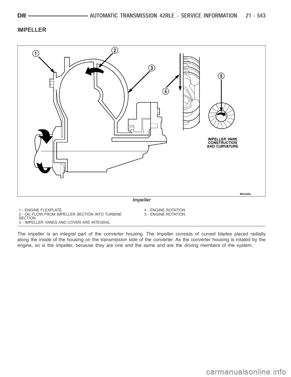
IMPELLER
The impeller is an integral part of the converter housing. The impeller consists of curved blades placed radially
along the inside of the housing on the transmission side of the converter. As the converter housing is rotated by the
engine, so is the impeller, because they are one and the same and are the driving members of the system.
Impeller
1 - ENGINE FLEXPLATE 4 - ENGINE ROTATION
2 - OIL FLOW FROM IMPELLER SECTION INTO TURBINE
SECTION5 - ENGINE ROTATION
3 - IMPELLER VANES AND COVER ARE INTEGRAL
Page 3065 of 5267
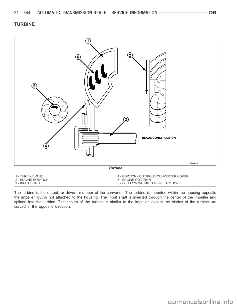
TURBINE
The turbine is the output, or driven, member of the converter. The turbine is mounted within the housing opposite
the impeller, but is not attached to the housing. The input shaft is inserted through the center of the impeller and
splined into the turbine. The design of the turbine is similar to the impeller, except the blades of the turbine are
curved in the opposite direction.
Turbine
1 - TURBINE VANE 4 - PORTION OF TORQUE CONVERTER COVER
2 - ENGINE ROTATION 5 - ENGINE ROTATION
3 - INPUT SHAFT 6 - OIL FLOW WITHIN TURBINE SECTION
Page 3067 of 5267
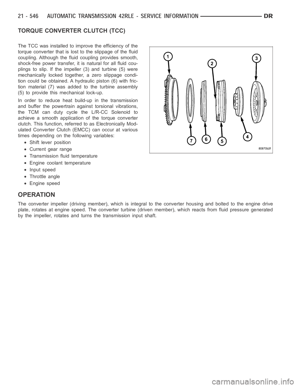
TORQUE CONVERTER CLUTCH (TCC)
The TCC was installed to improve the efficiency of the
torque converter that is lost to the slippage of the fluid
coupling. Although the fluid coupling provides smooth,
shock-free power transfer, it is natural for all fluid cou-
plings to slip. If the impeller (3) and turbine (5) were
mechanically locked together, a zero slippage condi-
tion could be obtained. A hydraulic piston (6) with fric-
tion material (7) was added to the turbine assembly
(5) to provide this mechanical lock-up.
In order to reduce heat build-up in the transmission
and buffer the powertrain against torsional vibrations,
the TCM can duty cycle the L/R-CC Solenoid to
achieve a smooth application of the torque converter
clutch. This function, referred to as Electronically Mod-
ulated Converter Clutch (EMCC) can occur at various
times depending on the following variables:
Shift lever position
Current gear range
Transmission fluid temperature
Engine coolant temperature
Input speed
Throttle angle
Engine speed
OPERATION
The converter impeller (driving member), which is integral to the converter housing and bolted to the engine drive
plate, rotates at engine speed. The converter turbine (driven member), which reacts from fluid pressure generated
by the impeller, rotates and turns the transmission input shaft.
Page 3069 of 5267
TORQUE CONVERTER CLUTCH (TCC)
In a standard torque converter, the impeller and tur-
bine are rotating at about the same speed and the
stator is freewheeling, providing no torque multiplica-
tion. By applying the turbine’s piston and friction mate-
rial to the front cover, a total converter engagement
can be obtained. The result of this engagement is a
direct 1:1 mechanical link between the engine and the
transmission.
The clutch can be engaged in second, third, fourth,
and fifth (if appicable) gear ranges depending on over-
drive control switch position. If the overdrive control
switch is in the normal ON position, the clutch will
engage after the shift to fourth gear. If the control
switch is in the OFF position, the clutch will engage
after the shift to third gear.
The TCM controls the torque converter by way of
internal logic software. The programming of the soft-
ware provides the TCM with control over the L/R-CC
Solenoid. There are four output logic states that can
be applied as follows:
No EMCC
Partial EMCC
Full EMCC
Gradual-to-no EMCC
NO EMCC
Under No EMCC conditions, the L/R Solenoid is OFF. There are several conditions that can result in NO EMCC
operations. No EMCC can be initiated due to a fault in the transmission or because the TCM does not see the need
for EMCC under current driving conditions.
PARTIAL EMCC
Partial EMCC operation modulates the L/R Solenoid (duty cycle) to obtain partial torque converter clutch application.
Partial EMCC operation is maintaineduntil Full EMCC is called for and actuated. During Partial EMCC some slip
does occur. Partial EMCC will usually occur at low speeds, low load and light throttle situations.
FULL EMCC
During Full EMCC operation, the TCM increases the L/R Solenoid duty cycle to full ON after Partial EMCC control
brings the engine speed within the desired slip range of transmission input speed relative to engine rpm.
GRADUAL-TO-NO EMCC
This operation is to soften the change from Full or Partial EMCC to No EMCC. This is done at mid-throttle by
decreasing the L/R Solenoid duty cycle.
REMOVAL
1. Remove transmission and torque converter from vehicle. (Refer to 21 - TRANSMISSION/AUTOMATIC - 45RFE/
545RFE - REMOVAL)
2. Place a suitable drain pan under the converter housing end of the transmission.
CAUTION: Verify that transmission is secure on the lifting device or work surface, the center of gravity of
the transmission will shift when the torque converter is removed creatingan unstable condition. The torque
converter is a heavy unit. Use caution when separating the torque converter from the transmission.
3. Pull the torque converter forward until the center hub clears the oil pumpseal.
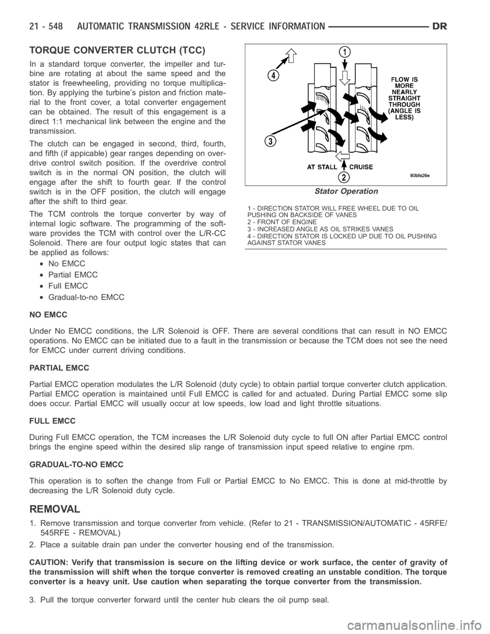
Stator Operation
1 - DIRECTION STATOR WILL FREE WHEEL DUE TO OIL
PUSHING ON BACKSIDE OF VANES
2-FRONTOFENGINE
3 - INCREASED ANGLE AS OIL STRIKES VANES
4 - DIRECTION STATOR IS LOCKED UP DUE TO OIL PUSHING
AGAINST STATOR VANES
Page 3077 of 5267
SENSOR-TRANSMISSION TEMPERATURE
DESCRIPTION
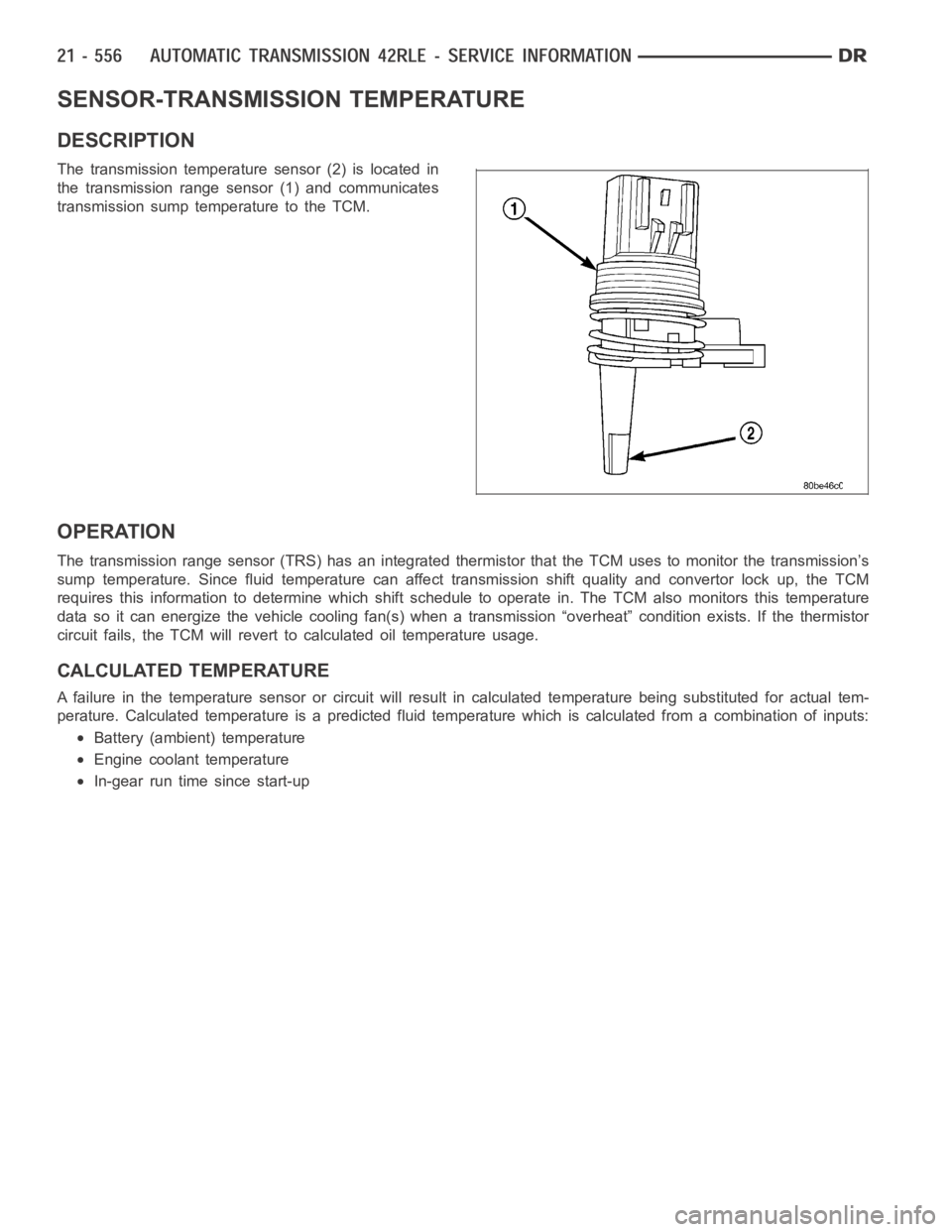
The transmission temperature sensor (2) is located in
the transmission range sensor (1) and communicates
transmission sump temperature to the TCM.
OPERATION
The transmission range sensor (TRS) has an integrated thermistor that theTCM uses to monitor the transmission’s
sump temperature. Since fluid temperature can affect transmission shiftquality and convertor lock up, the TCM
requires this information to determine which shift schedule to operate in. The TCM also monitors this temperature
data so it can energize the vehicle cooling fan(s) when a transmission “overheat” condition exists. If the thermistor
circuit fails, the TCM will revert to calculated oil temperature usage.
CALCULATED TEMPERATURE
A failure in the temperature sensor or circuit will result in calculated temperature being substituted for actual tem-
perature. Calculated temperature is a predicted fluid temperature whichis calculated from a combination of inputs:
Battery (ambient) temperature
Engine coolant temperature
In-gear run time since start-up
Page 3101 of 5267
page page
AUTOMATIC TRANSMISSION - 545RFE -
ELECTRICAL DIAGNOSTICS
DIAGNOSIS AND TESTING
P0122-TPS/APP CIRCUIT LOW............. 582
P0123-TPS/APP CIRCUIT HIGH............. 584
P0124-TPS/APP INTERMITTENT ............ 586
P0218-HIGH TEMPERATURE OPERATION
ACTIVATED............................... 588
P0562-BATTERY VOLTAGE LOW ............ 589
P0602-CONTROL MODULE PROGRAMMING
ERROR/NOT PROGRAMMED............... 594
P0604-INTERNAL CONTROL MODULE RAM . 595
P0605-INTERNAL CONTROL MODULE ROM . 596
P0613-INTERNAL TCM ..................... 597
P0706-TRANSMISSION RANGE SENSOR
RATIONALITY............................. 598
P0711-TRANSMISSION TEMPERATURE
SENSOR PERFORMANCE.................. 602
P0712-TRANSMISSION TEMPERATURE
SENSOR LOW............................. 605
P0713-TRANSMISSION TEMPERATURE
SENSOR HIGH............................ 608
P0714-TRANSMISSION TEMPERATURE
SENSOR INTERMITTENT................... 611
P0715-INPUT SPEED SENSOR 1 CIRCUIT . . . 614
P0720-OUTPUT SPEED SENSOR CIRCUIT . . 620
P0725-ENGINE SPEED SENSOR CIRCUIT . . . 626
P0731-GEAR RATIO ERROR IN 1ST ......... 628
P0732-GEAR RATIO ERROR IN 2ND ........ 631
P0733-GEAR RATIO ERROR IN 3RD ........ 637
P0734-GEAR RATIO ERROR IN 4TH ........ 643
P0735-GEAR RATIO ERROR IN 5TH ........ 647
P0736-GEAR RATIO ERROR IN REVERSE . . . 650
P0740-TCC OUT OF RANGE ................ 653
P0750-LR SOLENOID CIRCUIT............. 655
P0755-2C SOLENOID CIRCUIT............. 659
P0760-OD SOLENOID CIRCUIT ............. 663
P0765-UD SOLENOID CIRCUIT ............. 667
P0770-4C SOLENOID CIRCUIT............. 671
P0841-LR PRESSURE SWITCH
RATIONALITY............................. 675
P0845-2C HYDRAULIC PRESSURE TEST .... 682
P0846-2C PRESSURE SWITCH
RATIONALITY............................. 690
P0868-LINE PRESSURE LOW .............. 697
P0869-LINE PRESSURE HIGH .............. 703
P0870-OD HYDRAULIC PRESSURE TEST . . . 709
P0871-OD PRESSURE SWITCH
RATIONALITY............................. 717
P0875-UD HYDRAULIC PRESSURE TEST . . . 726P0876-UD PRESSURE SWITCH
RATIONALITY............................. 734
P0882-TCM POWER INPUT LOW ........... 741
P0883-TCM POWER INPUT HIGH ........... 745
P0884-POWER UPAT SPEED .............. 749
P0890-SWITCHED BATTERY ............... 751
P0932-LINE PRESSURE SENSOR CIRCUIT . . 755
P0934-LINE PRESSURE SENSOR CIRCUIT
LOW...................................... 758
P0935-LINE PRESSURE SENSOR CIRCUIT
HIGH..................................... 763
P0944-LOSS OF HYDRAULIC PUMP PRIME . 768
P0987-4C HYDRAULIC PRESSURE TEST . . . . 770
P0988-4C PRESSURE SWITCH
RATIONALITY............................. 778
P128B-TCM POWER CONTROL CIRCUIT 2
LOW - TIPM............................... 784
P128C-TCM POWER CONTROL CIRCUIT 2
HIGH - TIPM............................... 787
P128D-TCM POWER CONTROL CIRCUIT 2
OPEN - TIPM.............................. 790
P128E-TCM POWER CONTROL CIRCUIT 2
OVERCURRENT - TIPM.................... 793
P1684-BATTERY WAS DISCONNECTED . . . . . 797
P1715-RESTRICTED MANUAL VALVE IN T3
RANGE................................... 799
P1736-GEAR RATIO ERROR IN 2ND PRIME . 800
P1775-SOLENOID SWITCH VALVE
LATCHED IN TCC POSITION................ 805
P1776-SOLENOID SWITCH VALVE
LATCHED IN LR POSITION................. 809
P1790-FAULT IMMEDIATELY AFTER SHIFT . . 813
P1794-SPEED SENSOR GROUND ERROR . . 814
P2700-INADEQUATE ELEMENT VOLUME LR . 818
P2701-INADEQUATE ELEMENT VOLUME 2C . 820
P2702-INADEQUATE ELEMENT VOLUME
OD....................................... 822
P2703- INADEQUATE ELEMENT VOLUME
UD
........................................ 824
P2704-INADEQUATE ELEMENT VOLUME 4C . 826
P2706-MS SOLENOID CIRCUIT............. 828
U0002-CAN C BUS OFF PERFORMANCE . . . . 832
U0100-NO COMMUNICATION WITH THE
ECM/PCM................................. 834
U0121-LOST COMMUNICATION WITH ABS . . 836
U0141 LOST COMMUNICATION WITH FCM . . 838
STANDARD PROCEDURE
45RFE/545RFE PRE-DIAGNOSTIC
TROUBLESHOOTING PROCEDURE......... 840
45RFE/545RFE TRANSMISSION
VERIFICATION TEST - VER 1............... 841
Page 3103 of 5267
P0122-TPS/APP CIRCUIT LOW
For a complete wiring diagramRefer to Section 8W.
Theory of Operation
Due to the integration of the Powertrain and Transmission Control Modulesthe New Generation Control Module III
will be referred to as the Powertrain Control Module (PCM). The 3–wire TPS (4.7L V-8 Engine) provides the PCM
with an input signal voltage that represents the throttle blade position of the throttle body. The Throttle Position
Sensor (TPS) is connected to the throttle blade shaft. As the position of the throttle blade changes, the output volt-
age of the TPS changes.
The PCM supplies approximately 5.0 volts to the TPS. The TPS output voltage(input signal to the PCM) represents
the throttle blade position. The PCM receives an input signal voltage fromthe TPS. This will vary in an approximate
range from 0.26 volts at minimum throttle opening (idle), to 4.49 volts at maximum opening (wide open throttle).
The Accelerator Pedal Position Sensor (APPS) is currently used only with the 5.7L V-8 engine. The APPS is a linear
potentiometer. It provides the PCM with a voltage signal proportional to the angle, or position of the accelerator
pedal. The APPS signal along with inputs from other sensors is used by the PCM to calculate the throttle plate
position.
A mechanical cable is used between the accelerator pedal and the APPS assembly. Although a cable is used
between the accelerator pedal and the APPS assembly, a mechanical cable isnot used between the accelerator
pedal and the throttle body. The throttle plate position is electronically controlled by the PCM.
When Monitored:
Continuously with the ignition on and engine running.
Set Condition:
This DTC will set if the monitored TPS voltage drops below .078 volts for theperiod of 0.48 seconds.
Possible Causes
RELATED ENGINE TPS/APPS DTC’S PRESENT
POWERTRAIN CONTROL MODULE
Always perform the Pre-Diagnostic Troubleshooting procedure before proceeding. (Refer to 21 - TRANSMIS-
SION/TRANSAXLE/AUTOMATIC - 45RFE/545RFE - STANDARD PROCEDURE)
Diagnostic Test
1.CHECK IF RELATED ENGINE TPS/APPS DTC’S ARE PRESENT
With the scan tool, check Engine DTC’s.
Are there any Engine TPS/APPS DTCs present?
Ye s>>
Refer to the Driveability Category and perform the appropriate Symptom.
No>>
Go To 2
2.CHECK TO SEE IF DTC IS CURRENT
With the scan tool, record the DTC EVENT DATA to help identify the conditionsinwhichtheDTCwasset.
With the scan tool, erase Transmission DTCs.
NOTE: To erase DTC EVENT DATA information, a BATTERY DISCONNECT must be performed. Performing a
BATTERY DISCONNECT may reset learned Transmission values to controller defaults which may lead to
erratic shift schedules.
Drive the vehicle and try to duplicate the conditions in which the DTC was reported by the DTC EVENT DATA.
Page 3105 of 5267
P0123-TPS/APP CIRCUIT HIGH
For a complete wiring diagramRefer to Section 8W.
Theory of Operation
Due to the integration of the Powertrain and Transmission Control Modulesthe New Generation Control Module III
will be referred as the Powertrain Control Module (PCM). The 4.7L V-8 Throttle Positioning Sensor (TPS) provides
the PCM with an input signal voltage that represents the throttle blade position of the throttle body. The TPS is
connected to the throttle blade shaft. As the position of the throttle blade changes, the output voltage of the TPS
changes.
The 5.7L V-8 Accelerator Pedal Position Sensor (APPS) is a linear potentiometer that provides the PCM with a
voltage signal proportional to the angle, or position of the accelerator pedal. The APPS signal along with inputs from
other sensors is used by the PCM to calculate the throttle plate position which is electronically controlled.
When Monitored:
Continuously with the ignition on and engine running.
Set Condition:
This DTC will set if the monitored TPS voltage rises above 4.94 volts for theperiod of 0.48 seconds.
Possible Causes
RELATED ENGINE TPS/APPS DTC’S PRESENT
POWERTRAIN CONTROL MODULE
Always perform the Pre-Diagnostic Troubleshooting procedure before proceeding. (Refer to 21 - TRANSMIS-
SION/TRANSAXLE/AUTOMATIC - 45RFE/545RFE - STANDARD PROCEDURE)
Diagnostic Test
1.DETERMINING IF RELATED ENGINE TPS/APPS DTCS ARE PRESENT
With the scan tool, check Engine DTCs, this includes all one trip failures.
Are there any Engine TPS/APPS DTCs present?
Ye s>>
Refer to the Driveability category and perform the appropriate symptom.
No>>
Go To 2
2.CHECK IF THE DTC IS CURRENT
With the scan tool, record the DTC EVENT DATA to help identify the conditionsinwhichtheDTCwasset.
With the scan tool, erase Transmission DTCs.
NOTE: To erase DTC EVENT DATA information, a BATTERY DISCONNECT must be performed. Performing a
BATTERY DISCONNECT may reset all learned Transmission values to controller defaults that could lead to
an inconsistent shift schedule.
Drive the vehicle and try to duplicate the conditions in which the DTC was reported by the DTC EVENT DATA.
With the scan tool, read Transmission DTCs.
Did the DTC P0123 TPS/APPS HIGH, reset?
Ye s>>
Using the schematics as a guide, check the Powertrain Control Module (PCM)terminals for corrosion,
damage, or terminal push out. Pay particular attention to all power and ground circuits. If no problems
are found, replace the PCM per the Service Information. With the scan tool,perform QUICK LEARN.
Perform 45RFE/545RFE TRANSMISSION VERIFICATION TEST - VER 1. (Refer to 21- TRANSMIS-
SION/TRANSAXLE/AUTOMATIC - 45RFE/545RFE - STANDARD PROCEDURE)
No>>
Go To 3