Page 1631 of 5267
9. Disconnect crankshaft position sensor (1).
NOTE: The following step applies to 4X4vehicles equipped with automatic transmission only.
10.4X4 vehiclesRemove the axle isolator bracket from the engine, transmission and the axle.
11. Remove structural cover (Refer to 9 - ENGINE/
ENGINE BLOCK/STRUCTURAL COVER -
REMOVAL).
12. Remove starter (4) (Refer to 8 - ELECTRICAL/
STARTING/STARTER MOTOR - REMOVAL).
Page 1632 of 5267
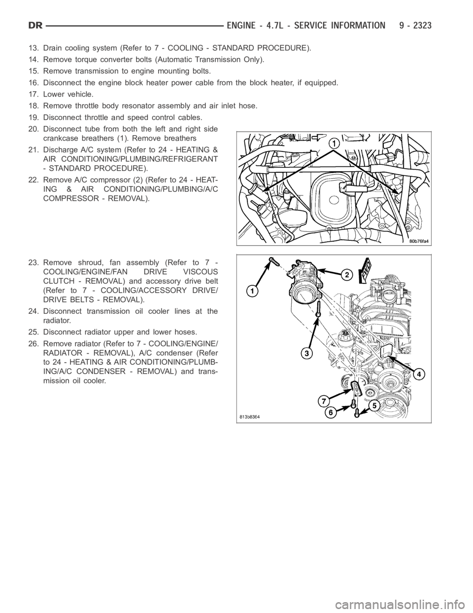
13. Drain cooling system (Refer to 7 - COOLING - STANDARD PROCEDURE).
14. Remove torque converter bolts (Automatic Transmission Only).
15. Remove transmission to engine mounting bolts.
16. Disconnect the engine block heater power cable from the block heater, if equipped.
17. Lower vehicle.
18. Remove throttle body resonator assembly and air inlet hose.
19. Disconnect throttle and speed control cables.
20. Disconnect tube from both the left and right side
crankcase breathers (1). Remove breathers
21. Discharge A/C system (Refer to 24 - HEATING &
AIR CONDITIONING/PLUMBING/REFRIGERANT
- STANDARD PROCEDURE).
22. Remove A/C compressor (2) (Refer to 24 - HEAT-
ING & AIR CONDITIONING/PLUMBING/A/C
COMPRESSOR - REMOVAL).
23. Remove shroud, fan assembly (Refer to 7 -
COOLING/ENGINE/FAN DRIVE VISCOUS
CLUTCH - REMOVAL) and accessory drive belt
(Refer to 7 - COOLING/ACCESSORY DRIVE/
DRIVE BELTS - REMOVAL).
24. Disconnect transmission oil cooler lines at the
radiator.
25. Disconnect radiator upper and lower hoses.
26. Remove radiator (Refer to 7 - COOLING/ENGINE/
RADIATOR - REMOVAL), A/C condenser (Refer
to 24 - HEATING & AIR CONDITIONING/PLUMB-
ING/A/C CONDENSER - REMOVAL) and trans-
mission oil cooler.
Page 1634 of 5267
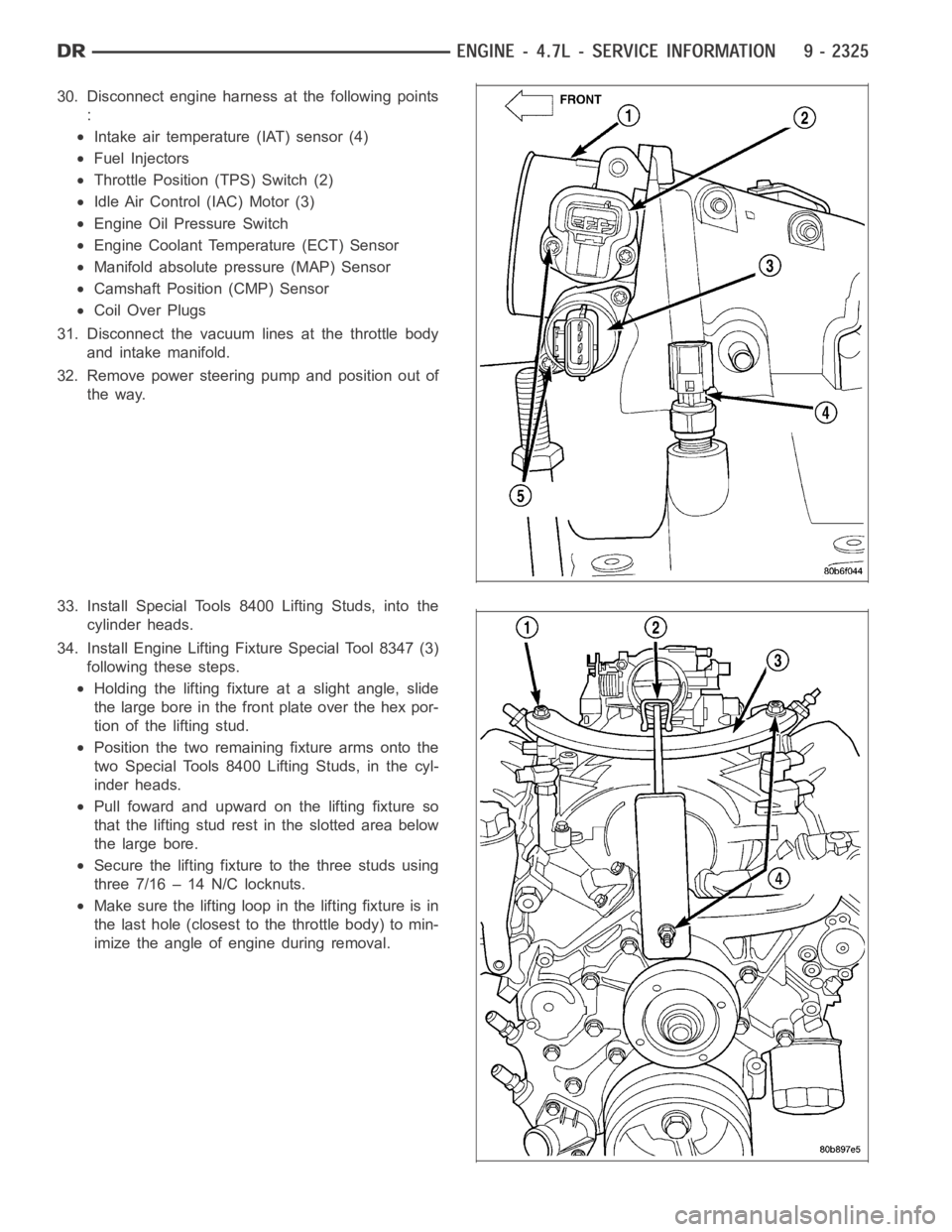
30. Disconnect engine harness at the following points
:
Intake air temperature (IAT) sensor (4)
Fuel Injectors
Throttle Position (TPS) Switch (2)
Idle Air Control (IAC) Motor (3)
Engine Oil Pressure Switch
Engine Coolant Temperature (ECT) Sensor
Manifold absolute pressure (MAP) Sensor
Camshaft Position (CMP) Sensor
Coil Over Plugs
31. Disconnect the vacuum lines at the throttle body
and intake manifold.
32. Remove power steering pump and position out of
the way.
33. Install Special Tools 8400 Lifting Studs, into the
cylinder heads.
34. Install Engine Lifting Fixture Special Tool 8347 (3)
following these steps.
Holding the lifting fixture at a slight angle, slide
the large bore in the front plate over the hex por-
tion of the lifting stud.
Position the two remaining fixture arms onto the
two Special Tools 8400 Lifting Studs, in the cyl-
inder heads.
Pull foward and upward on the lifting fixture so
that the lifting stud rest in the slotted area below
the large bore.
Secure the lifting fixture to the three studs using
three 7/16 – 14 N/C locknuts.
Make sure the lifting loop in the lifting fixture is in
the last hole (closest to the throttle body) to min-
imize the angle of engine during removal.
Page 1636 of 5267
INSTALLATION
1. Position engine in the vehicle.
Position both the left and right side engine mount
brackets and install the through bolts and nuts.
Tighten nuts to4X2 vehicles95 Nꞏm (70 ft. lbs.).4X4
vehicles102Nꞏm(75ft.lbs.).
2.4X4 vehiclesInstall locknuts onto the engine mount
brackets. Tighten locknuts to 41 Nꞏm (30 ft. lbs.).
3. Remove jack from under the transmission.
4. Remove Engine Lifting Fixture Special Tool 8347
(3).
5. Remove Special Tools 8400 Lifting Studs.
Page 1639 of 5267
19. Install A/C compressor (2) (Refer to 24 - HEAT-
ING & AIR CONDITIONING/PLUMBING/A/C
COMPRESSOR - INSTALLATION).
20. Install both breathers (1). Connect tube to both
crankcase breathers.
21. Connect throttle and speed control cables.
22. Install throttle body resonator assembly and air
inlet hose. Tighten clamps 4 Nꞏm (35 in. lbs.).
23. Raise vehicle.
24. Install transmission to engine mounting bolts.
Tighten the bolts to 41 Nꞏm (30 ft. lbs.).
25. Install torque converter bolts (Automatic Transmis-
sion Only).
26. Connect crankshaft position sensor (1).
27.4X4 vehiclesPosition and install the axle isolator
bracket onto the axle, transmission and engine
block. Tighten bolts to specification (Refer to 9 -
ENGINE - SPECIFICATIONS).
Page 1640 of 5267
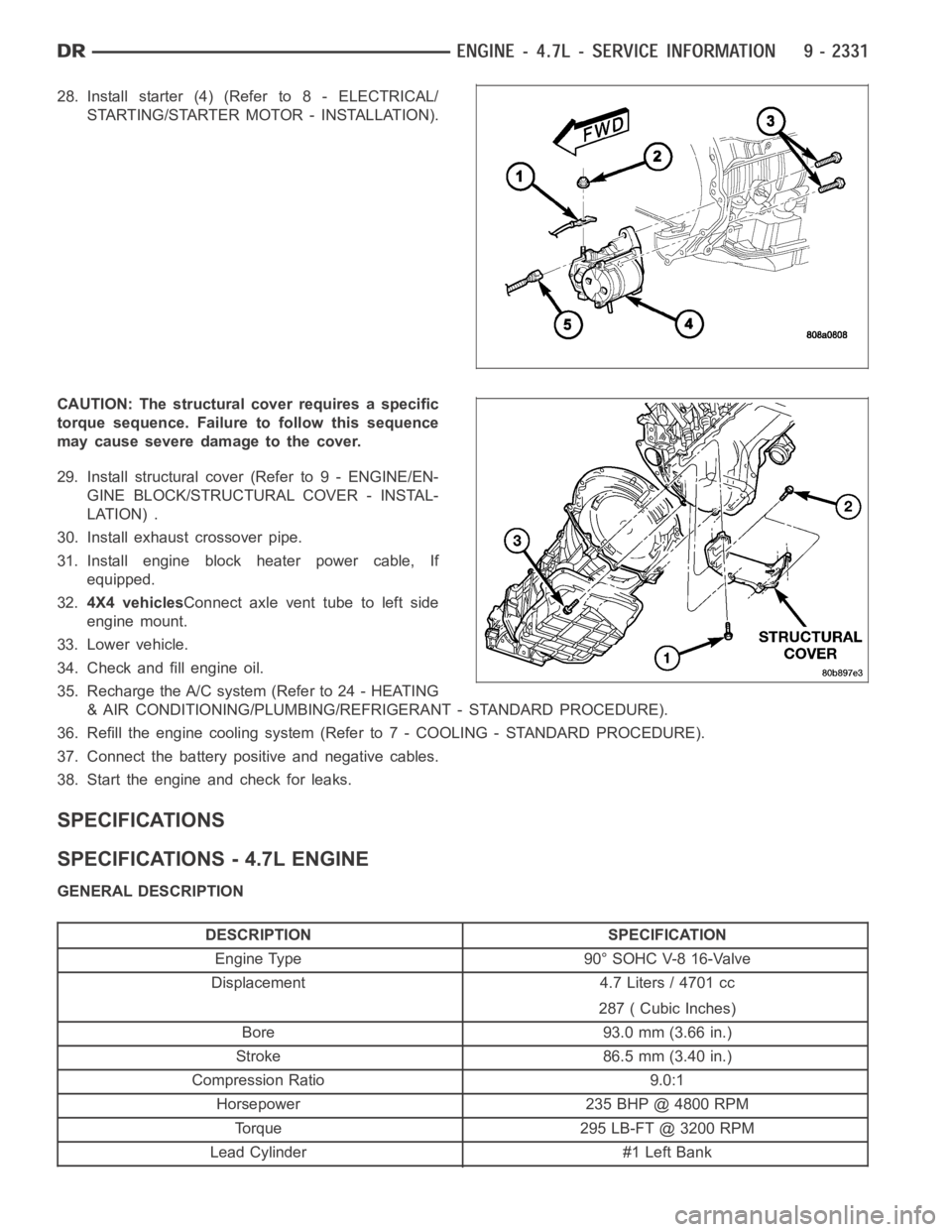
28. Install starter (4) (Refer to 8 - ELECTRICAL/
STARTING/STARTER MOTOR - INSTALLATION).
CAUTION: The structural cover requires a specific
torque sequence. Failure to follow this sequence
may cause severe damage to the cover.
29. Install structural cover (Refer to 9 - ENGINE/EN-
GINE BLOCK/STRUCTURAL COVER - INSTAL-
LATION) .
30. Install exhaust crossover pipe.
31. Install engine block heater power cable, If
equipped.
32.4X4 vehiclesConnect axle vent tube to left side
engine mount.
33. Lower vehicle.
34. Check and fill engine oil.
35. Recharge the A/C system (Refer to 24 - HEATING
& AIR CONDITIONING/PLUMBING/REFRIGERANT - STANDARD PROCEDURE).
36. Refill the engine cooling system (Refer to 7 - COOLING - STANDARD PROCEDURE).
37. Connect the battery positive and negative cables.
38. Start the engine and check for leaks.
SPECIFICATIONS
SPECIFICATIONS - 4.7L ENGINE
GENERAL DESCRIPTION
DESCRIPTION SPECIFICATION
Engine Type 90° SOHC V-8 16-Valve
Displacement 4.7 Liters / 4701 cc
287 ( Cubic Inches)
Bore 93.0 mm (3.66 in.)
Stroke 86.5 mm (3.40 in.)
Compression Ratio 9.0:1
Horsepower 235 BHP @ 4800 RPM
Torque 295 LB-FT @ 3200 RPM
Lead Cylinder #1 Left Bank
Page 1641 of 5267
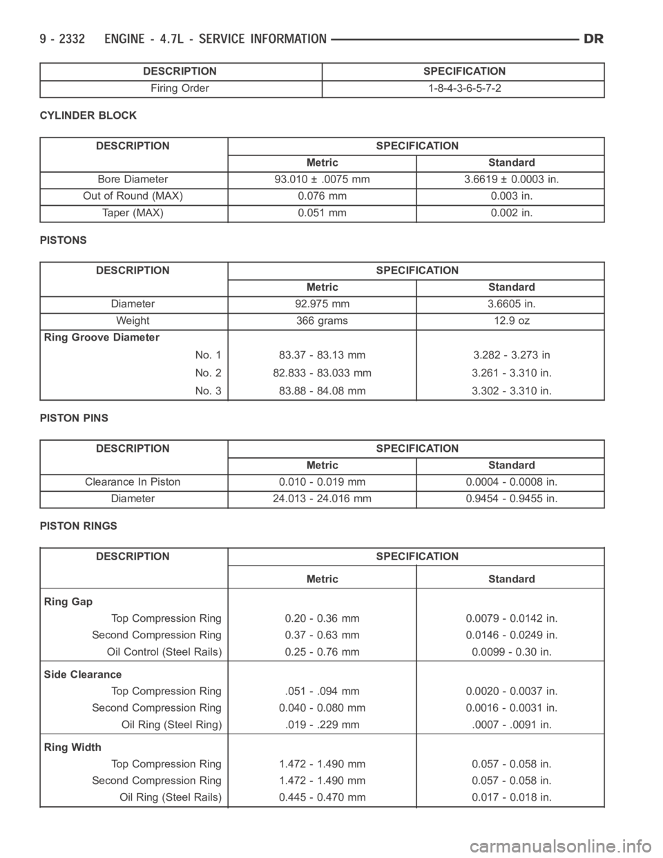
DESCRIPTION SPECIFICATION
Firing Order 1-8-4-3-6-5-7-2
CYLINDER BLOCK
DESCRIPTION SPECIFICATION
Metric Standard
Bore Diameter 93.010 ± .0075 mm 3.6619 ± 0.0003 in.
Out of Round (MAX) 0.076 mm 0.003 in.
Taper (MAX) 0.051 mm 0.002 in.
PISTONS
DESCRIPTION SPECIFICATION
Metric Standard
Diameter 92.975 mm 3.6605 in.
Weight 366 grams 12.9 oz
Ring Groove Diameter
No. 1 83.37 - 83.13 mm 3.282 - 3.273 in
No. 2 82.833 - 83.033 mm 3.261 - 3.310 in.
No. 3 83.88 - 84.08 mm 3.302 - 3.310 in.
PISTON PINS
DESCRIPTION SPECIFICATION
Metric Standard
Clearance In Piston 0.010 - 0.019 mm 0.0004 - 0.0008 in.
Diameter 24.013 - 24.016 mm 0.9454 - 0.9455 in.
PISTON RINGS
DESCRIPTION SPECIFICATION
Metric Standard
Ring Gap
Top Compression Ring 0.20 - 0.36 mm 0.0079 - 0.0142 in.
Second Compression Ring 0.37 - 0.63 mm 0.0146 - 0.0249 in.
Oil Control (Steel Rails) 0.25 - 0.76 mm 0.0099 - 0.30 in.
Side Clearance
Top Compression Ring .051 - .094 mm 0.0020 - 0.0037 in.
Second Compression Ring 0.040 - 0.080 mm 0.0016 - 0.0031 in.
Oil Ring (Steel Ring) .019 - .229 mm .0007 - .0091 in.
Ring Width
Top Compression Ring 1.472 - 1.490 mm 0.057 - 0.058 in.
Second Compression Ring 1.472 - 1.490 mm 0.057 - 0.058 in.
Oil Ring (Steel Rails) 0.445 - 0.470 mm 0.017 - 0.018 in.
Page 1645 of 5267
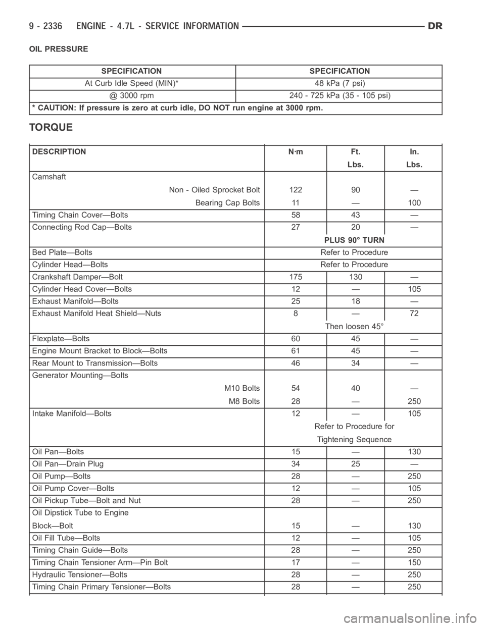
OIL PRESSURE
SPECIFICATION SPECIFICATION
At Curb Idle Speed (MIN)* 48 kPa (7 psi)
@ 3000 rpm 240 - 725 kPa (35 - 105 psi)
* CAUTION: If pressure is zero at curb idle, DO NOT run engine at 3000 rpm.
TORQUE
DESCRIPTION Nꞏm Ft. In.
Lbs. Lbs.
Camshaft
Non - Oiled Sprocket Bolt 122 90 —
Bearing Cap Bolts 11 — 100
Timing Chain Cover—Bolts 58 43 —
Connecting Rod Cap—Bolts 27 20 —
PLUS 90° TURN
Bed Plate—Bolts Refer to Procedure
Cylinder Head—Bolts Refer to Procedure
Crankshaft Damper—Bolt 175 130 —
Cylinder Head Cover—Bolts 12 — 105
Exhaust Manifold—Bolts 25 18 —
Exhaust Manifold Heat Shield—Nuts 8 — 72
Then loosen 45°
Flexplate—Bolts 60 45 —
Engine Mount Bracket to Block—Bolts 61 45 —
Rear Mount to Transmission—Bolts 46 34 —
Generator Mounting—Bolts
M10 Bolts 54 40 —
M8 Bolts 28 — 250
Intake Manifold—Bolts 12 — 105
Refer to Procedure for
Tightening Sequence
Oil Pan—Bolts 15 — 130
Oil Pan—Drain Plug 34 25 —
Oil Pump—Bolts 28 — 250
Oil Pump Cover—Bolts 12 — 105
Oil Pickup Tube—Bolt and Nut 28 — 250
Oil Dipstick Tube to Engine
Block—Bolt 15 — 130
Oil Fill Tube—Bolts 12 — 105
Timing Chain Guide—Bolts 28 — 250
Timing Chain Tensioner Arm—Pin Bolt 17 — 150
Hydraulic Tensioner—Bolts 28 — 250
Timing Chain Primary Tensioner—Bolts 28 — 250