2006 DODGE RAM SRT-10 lock
[x] Cancel search: lockPage 1617 of 5267
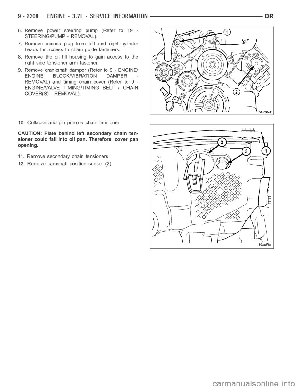
6. Remove power steering pump (Refer to 19 -
STEERING/PUMP - REMOVAL).
7. Remove access plug from left and right cylinder
heads for access to chain guide fasteners.
8. Remove the oil fill housing to gain access to the
right side tensioner arm fastener.
9. Remove crankshaft damper (Refer to 9 - ENGINE/
ENGINE BLOCK/VIBRATION DAMPER -
REMOVAL) and timing chain cover (Refer to 9 -
ENGINE/VALVE TIMING/TIMING BELT / CHAIN
COVER(S) - REMOVAL).
10. Collapse and pin primary chain tensioner.
CAUTION: Plate behind left secondary chain ten-
sioner could fall into oil pan. Therefore, cover pan
opening.
11. Remove secondary chain tensioners.
12. Remove camshaft position sensor (2).
Page 1618 of 5267
CAUTION: Care should be taken not to damage
camshaft target wheel. Do not hold target wheel
while loosening or tightening camshaft sprocket.
Do not place the target wheel near a magnetic
source of any kind. A damaged or magnetized tar-
get wheel could cause a vehicle no start condition.
CAUTION: Do not forcefully rotate the camshafts
or crankshaft independently of each other. Damag-
ing intake valve to piston contact will occur.
Ensure negative battery cable is disconnected to
guard against accidental starter engagement.
13. Remove left and right camshaft sprocket bolts.
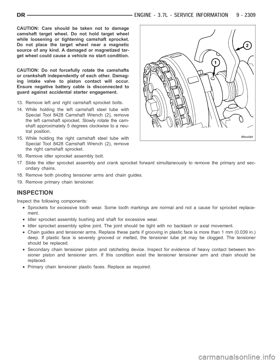
14. While holding the left camshaft steel tube with
Special Tool 8428 Camshaft Wrench (2), remove
the left camshaft sprocket. Slowly rotate the cam-
shaft approximately 5 degrees clockwise to a neu-
tral position.
15. While holding the right camshaft steel tube with
Special Tool 8428 Camshaft Wrench (2), remove
the right camshaft sprocket.
16. Remove idler sprocket assembly bolt.
17. Slide the idler sprocket assembly and crank sprocket forward simultaneously to remove the primary and sec-
ondary chains.
18. Remove both pivoting tensioner arms and chain guides.
19. Remove primary chain tensioner.
INSPECTION
Inspect the following components:
Sprockets for excessive tooth wear. Some tooth markings are normal and nota cause for sprocket replace-
ment.
Idler sprocket assembly bushing and shaft for excessive wear.
Idler sprocket assembly spline joint. The joint should be tight with no backlash or axial movement.
Chain guides and tensioner arms. Replace these parts if grooving in plasticfaceismorethan1mm(0.039in.)
deep. If plastic face is severely grooved or melted, the tensioner lube jetmay be clogged. The tensioner
should be replaced.
Secondary chain tensioner piston and ratcheting device. Inspect for evidence of heavy contact between ten-
sioner piston and tensioner arm. If this condition exist the tensioner tensioner arm and chain should be
replaced.
Primary chain tensioner plastic faces. Replace as required.
Page 1619 of 5267
INSTALLATION
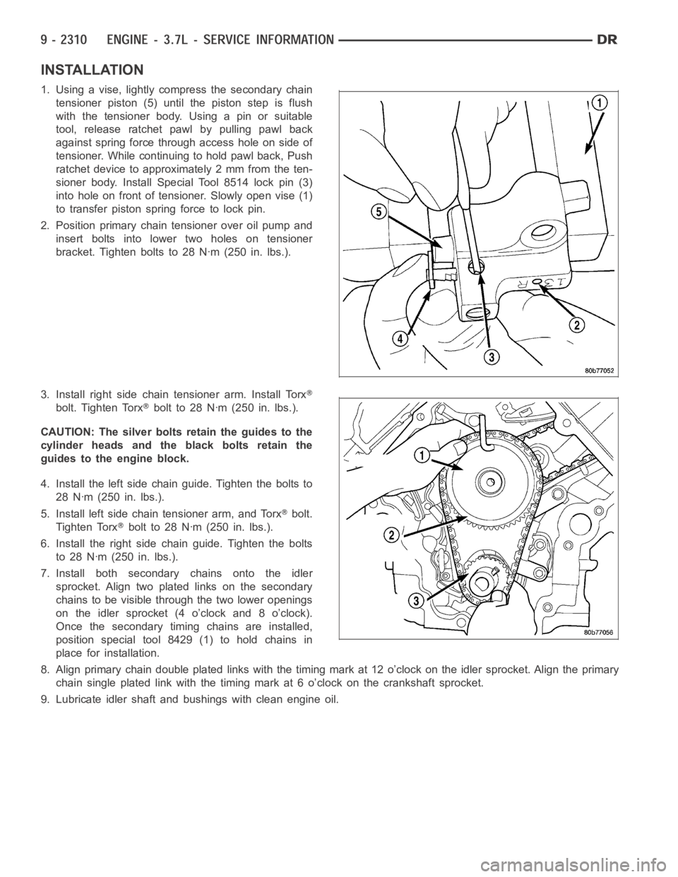
1. Using a vise, lightly compress the secondary chain
tensioner piston (5) until the piston step is flush
with the tensioner body. Using a pin or suitable
tool, release ratchet pawl by pulling pawl back
against spring force through access hole on side of
tensioner. While continuing to hold pawl back, Push
ratchet device to approximately 2 mm from the ten-
sioner body. Install Special Tool 8514 lock pin (3)
into hole on front of tensioner. Slowly open vise (1)
to transfer piston spring force to lock pin.
2. Position primary chain tensioner over oil pump and
insert bolts into lower two holes on tensioner
bracket. Tighten bolts to 28 Nꞏm (250 in. lbs.).
3. Install right side chain tensioner arm. Install Torx
bolt. Tighten Torxbolt to 28 Nꞏm (250 in. lbs.).
CAUTION: The silver bolts retain the guides to the
cylinder heads and the black bolts retain the
guides to the engine block.
4. Install the left side chain guide. Tighten the bolts to
28 Nꞏm (250 in. lbs.).
5. Install left side chain tensioner arm, and Torx
bolt.
Tighten Torx
bolt to 28 Nꞏm (250 in. lbs.).
6. Install the right side chain guide. Tighten the bolts
to 28 Nꞏm (250 in. lbs.).
7. Install both secondary chains onto the idler
sprocket. Align two plated links on the secondary
chains to be visible through the two lower openings
on the idler sprocket (4 o’clock and 8 o’clock).
Once the secondary timing chains are installed,
position special tool 8429 (1) to hold chains in
place for installation.
8. Align primary chain double platedlinks with the timing mark at 12 o’clock on the idler sprocket. Align the primary
chain single plated link with the timing mark at 6 o’clock on the crankshaftsprocket.
9. Lubricate idler shaft and bushings with clean engine oil.
Page 1620 of 5267
NOTE: The idler sprocket must be timed to the
counterbalance shaft drive gear before the idler
sprocket is fully seated.
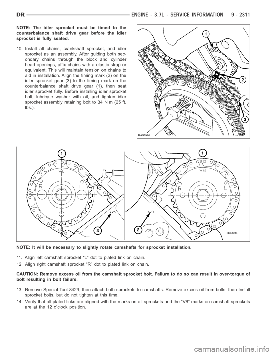
10. Install all chains, crankshaft sprocket, and idler
sprocket as an assembly. After guiding both sec-
ondary chains through the block and cylinder
head openings, affix chains with a elastic strap or
equivalent. This will maintain tension on chains to
aid in installation. Align the timing mark (2) on the
idler sprocket gear (3) to the timing mark on the
counterbalance shaft drive gear (1), then seat
idler sprocket fully. Before installing idler sprocket
bolt, lubricate washer with oil, and tighten idler
sprocketassemblyretainingboltto34Nꞏm(25ft.
lbs.).
NOTE: It will be necessary to slightly rotate camshafts for sprocket installation.
11. Align left camshaft sprocket “L” dot to plated link on chain.
12. Align right camshaft sprocket “R” dot to plated link on chain.
CAUTION: Remove excess oil from the camshaft sprocket bolt. Failure to do so can result in over-torque of
bolt resulting in bolt failure.
13. Remove Special Tool 8429, then attach both sprockets to camshafts. Remove excess oil from bolts, then Install
sprocket bolts, but do not tighten at this time.
14. Verify that all plated links are aligned with the marks on all sprocketsand the “V6” marks on camshaft sprockets
are at the 12 o’clock position.
Page 1621 of 5267
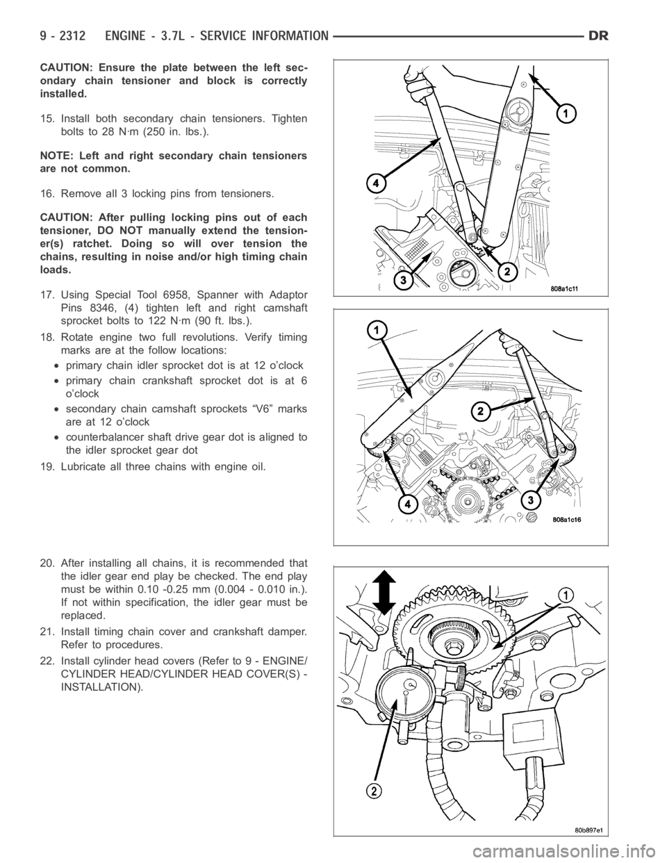
CAUTION: Ensure the plate between the left sec-
ondary chain tensioner and block is correctly
installed.
15. Install both secondary chain tensioners. Tighten
boltsto28Nꞏm(250in.lbs.).
NOTE: Left and right secondary chain tensioners
are not common.
16. Remove all 3 locking pins from tensioners.
CAUTION: After pulling locking pins out of each
tensioner, DO NOT manually extend the tension-
er(s) ratchet. Doing so will over tension the
chains, resulting in noise and/or high timing chain
loads.
17. Using Special Tool 6958, Spanner with Adaptor
Pins 8346, (4) tighten left and right camshaft
sprocket bolts to 122 Nꞏm (90 ft. lbs.).
18. Rotate engine two full revolutions. Verify timing
marks are at the follow locations:
primary chain idler sprocket dot is at 12 o’clock
primary chain crankshaft sprocket dot is at 6
o’clock
secondary chain camshaft sprockets “V6” marks
are at 12 o’clock
counterbalancer shaft drive gear dot is aligned to
the idler sprocket gear dot
19. Lubricate all three chains with engine oil.
20. After installing all chains, it is recommended that
the idler gear end play be checked. The end play
must be within 0.10 -0.25 mm (0.004 - 0.010 in.).
If not within specification, the idler gear must be
replaced.
21. Install timing chain cover and crankshaft damper.
Refer to procedures.
22. Install cylinder head covers (Refer to 9 - ENGINE/
CYLINDER HEAD/CYLINDER HEAD COVER(S) -
INSTALLATION).
Page 1623 of 5267
page page
ENGINE - 4.7L - SERVICE INFORMATION
DIAGNOSIS AND TESTING
DIAGNOSIS AND TESTING - ENGINE
DIAGNOSIS - PERFORMANCE............. 2316
DIAGNOSIS AND TESTING - ENGINE
DIAGNOSIS - MECHANICAL............... 2318
DIAGNOSIS AND TESTING - CYLINDER
COMPRESSION PRESSURE............... 2318
DIAGNOSIS AND TESTING - CYLINDER
COMBUSTION PRESSURE LEAKAGE...... 2319
DIAGNOSIS AND TESTING - ENGINE
DIAGNOSIS - INTRODUCTION............. 2320
STANDARD PROCEDURE
STANDARD PROCEDURE - REPAIR
DAMAGED OR WORN THREADS.......... 2320
STANDARD PROCEDURE - FORM-IN-
PLACE GASKETS AND SEALERS.......... 2320
REMOVAL ................................. 2321
INSTALLATION ............................. 2327
SPECIFICATIONS
SPECIFICATIONS - 4.7L ENGINE .......... 2331
TORQUE ................................. 2336
SPECIAL TOOLS
4.7L ENGINE ............................. 2338
ELEMENT - AIR CLEANER
REMOVAL ................................. 2342
INSTALLATION ............................. 2343
CYLINDER HEAD
DESCRIPTION
DESCRIPTION - CYLINDER HEAD ......... 2344
DESCRIPTION - VALVE GUIDES ........... 2344
DIAGNOSIS AND TESTING
CYLINDER HEAD GASKET................ 2344
REMOVAL
REMOVAL - LEFT CYLINDER HEAD ........ 2345
REMOVAL - RIGHT CYLINDER HEAD ...... 2348
CLEANING ................................. 2350
INSPECTION ............................... 2350
INSTALLATION
INSTALLATION - LEFT CYLINDER HEAD . . . 2351
INSTALLATION - RIGHT CYLINDER HEAD . . 2353
CAMSHAFT - LEFT
DESCRIPTION ............................. 2357
REMOVAL ................................. 2357
INSTALLATION ............................. 2359
CAMSHAFT - RIGHT
DESCRIPTION ............................. 2362
REMOVAL ................................. 2362
INSTALLATION ............................. 2365
COVER - CYLINDER HEAD
DESCRIPTION ............................. 2369REMOVAL
REMOVAL - RIGHT SIDE .................. 2369
REMOVAL - LEFT SIDE ................... 2369
CLEANING ................................. 2369
INSTALLATION
INSTALLATION - RIGHT SIDE .............. 2370
INSTALLATION - LEFT SIDE ............... 2370
VALVES & SEATS - INTAKE/EXHAUST
DESCRIPTION ............................. 2371
REMOVAL ................................. 2371
INSTALLATION ............................. 2372
ROCKER ARM - VALVE
DESCRIPTION ............................. 2374
DIAGNOSIS AND TESTING - HYDRAULIC
LASH ADJUSTER ......................... 2374
REMOVAL ................................. 2374
INSTALLATION ............................. 2375
SPRINGS-VALVE
DESCRIPTION ............................. 2376
REMOVAL ................................. 2376
INSTALLATION ............................. 2377
SEALS-VALVE GUIDE
DESCRIPTION ............................. 2378
ENGINE BLOCK
DESCRIPTION ............................. 2379
STANDARD PROCEDURE - CYLINDER BORE
HONING ................................. 2379
CLEANING ................................. 2379
INSPECTION............................... 2380
BEARINGS - CONNECTING ROD
STANDARD PROCEDURE - CONNECTING
ROD BEARING FITTING ................... 2381
PLUGS - CORE
REMOVAL ................................. 2384
INSTALLATION ............................. 2384
CRANKSHAFT
DESCRIPTION ............................. 2385
REMOVAL ................................. 2385
INSPECTION............................... 2386
INSTALLATION ............................. 2386
BEARINGS - CRANKSHAFT MAIN
STANDARD PROCEDURE - CRANKSHAFT
MAIN BEARING - FITTING ................. 2389
INSPECTION............................... 2390
SEAL - CRANKSHAFT OIL - FRONT
REMOVAL ................................. 2391
INSTALLATION ............................. 2392
SEAL - CRANKSHAFT OIL - REAR
DIAGNOSIS AND TESTING - REAR SEAL
AREA LEAKS . ............................ 2393
REMOVAL ................................. 2393
Page 1628 of 5267
Ensurethebatteryiscompletelychargedandtheenginestartermotorisingood operating condition. Otherwise the
indicated compression pressures may not be valid for diagnosis purposes.
1. Clean the spark plug recesses with compressed air.
2. Remove the spark plugs.
3. Disable the fuel system (Refer to 14 - FUEL SYSTEM/FUEL DELIVERY - DESCRIPTION).
4. Remove the ASD relay (Refer to 8 - ELECTRICAL/IGNITION CONTROL/AUTO SHUTDOWNRELAY-
REMOVAL).
5. Insert a compression pressure gauge and rotate the engine with the engine starter motor for three revolutions.
6. Record the compression pressure on the 3rd revolution. Continue the test for the remaining cylinders.
7. (Refer to 9 - ENGINE - SPECIFICATIONS) for the correct engine compression pressures.
DIAGNOSIS AND TESTING - CYLINDERCOMBUSTION PRESSURE LEAKAGE
The combustion pressure leakage test provides an accurate means for determining engine condition.
Combustion pressure leakage testing will detect:
Exhaust and intake valve leaks (improper seating).
Leaks between adjacent cylinders or into water jacket.
Any causes for combustion/compression pressure loss.
1. Check the coolant level and fill as required. DO NOT install the radiatorcap.
2. Start and operate the engine until it attains normal operating temperature, then turn the engine OFF.
3. Remove the spark plugs.
4. Remove the oil filler cap.
5. Remove the air cleaner hose.
6. Calibrate the tester according to the manufacturer’s instructions. The shop air source for testing should maintain
483 kPa (70 psi) minimum, 1,379 kPa (200 psi) maximum and 552 kPa (80 psi) recommended.
7. Perform the test procedures on each cylinder according to the tester manufacturer’s instructions. Set piston of
cylinder to be tested at TDC compression,While testing, listen for pressurized air escaping through the throttle
body, tailpipe and oil filler cap opening. Check for bubbles in the radiator coolant.
All gauge pressure indications should be equal, with no more than 25% leakage.
FOR EXAMPLE:At 552 kPa (80 psi) input pressure, a minimum of 414 kPa (60 psi) should be maintained in the
cylinder.
Refer to CYLINDER COMBUSTION PRESSURE LEAKAGE DIAGNOSIS CHART .
CYLINDER COMBUSTION PRESSURE LEAKAGE DIAGNOSIS CHART
CONDITION POSSIBLE CAUSE CORRECTION
AIR ESCAPES THROUGH
THROTTLE BODYIntake valve bent, burnt, or not
seated properlyInspect valve and valve seat.
Reface or replace, as necessary.
Inspect valve springs. Replace as
necessary.
AIR ESCAPES THROUGH
TAILPIPEExhaust valve bent, burnt, or not
seated properlyInspect valve and valve seat.
Reface or replace, as necessary.
Inspect valve springs. Replace as
necessary.
AIR ESCAPES THROUGH
RADIATORHead gasket leaking or cracked
cylinder head or blockRemove cylinder head and inspect.
Replace defective part
MORE THAN 50% LEAKAGE
FROM ADJACENT CYLINDERSHead gasket leaking or crack in
cylinder head or block between
adjacent cylindersRemove cylinder head and inspect.
Replace gasket, head, or block as
necessary
Page 1630 of 5267
able in three ounce tubes and has a shelf life of one year. After one year thismaterial will not properly cure. Always
inspect the package for the expiration date before use.
MOPAR
GASKET MAKER
Mopar
Gasket Maker is an anaerobic type gasket material. The material cures in the absence of air when
squeezed between two metallic surfaces. It will not cure if left in the uncovered tube. The anaerobic material is for
use between two machined surfaces. Do not use on flexible metal flanges.
MOPAR
GASKET SEALANT
Mopar
Gasket Sealant is a slow drying, permanently soft sealer. This material isrecommended for sealing
threaded fittings and gaskets against leakage of oil and coolant. Can be used on threaded and machined parts
under all temperatures. This material is used on engines with multi-layersteel (MLS) cylinder head gaskets. This
material also will prevent corrosion. Mopar
Gasket Sealant is available in a 13 oz. aerosol can or 4oz./16 oz. can
w/applicator.
FORM-IN-PLACE GASKET AND SEALER APPLICATION
Assembling parts using a form-in-place gasket requires care but it’s easier than using precut gaskets.
Mopar
Gasket Maker material should be applied sparingly 1 mm (0.040 in.) diameter or less of sealant to one
gasket surface. Be certain the material surrounds each mounting hole. Excess material can easily be wiped off.
Components should be torqued in place within 15 minutes. The use of a locating dowel is recommended during
assembly to prevent smearing material off the location.
Mopar
Engine RTV GEN II or ATF RTV gasket material should be applied in a continuous bead approximately 3
mm (0.120 in.) in diameter. All mounting holes must be circled. For corner sealing, a 3.17 or 6.35 mm (1/8 or 1/4 in.)
drop is placed in the center of the gasket contact area. Uncured sealant maybe removed with a shop towel. Com-
ponents should be torqued in place while the sealant is still wet to the touch (within 10 minutes). The usage of a
locating dowel is recommended during assembly to prevent smearing material off the location.
Mopar
Gasket Sealant in an aerosol can should be applied using a thin, even coat sprayed completely over both
surfaces to be joined, and both sides of a gasket. Then proceed with assembly. Material in a can w/applicator can
be brushed on evenly over the sealing surfaces. Material in an aerosol can shouldbeusedonengineswithmulti-
layer steel gaskets.
REMOVAL
NOTE:Thisprocedureappliestoboththe4X2and4X4vehicles,stepsthatapply to the 4X4 vehicle only,
are identified.
1. Release fuel rail pressure (Refer to 14 - FUEL SYSTEM/FUEL DELIVERY - STANDARD PROCEDURE) then
disconnect the fuel supply quick connect fitting at the fuel rail (Refer to14 - FUEL SYSTEM/FUEL DELIVERY/
QUICK CONNECT FITTING - STANDARD PROCEDURE).
2. Disconnect the battery negative and positive cables.
3. Raise vehicle on hoist.
4. Remove exhaust crossover pipe from exhaust manifolds.
5.4X4 vehiclesDisconnect axle vent tube from left side engine mount.
6. Remove the through bolt retaining nut and bolt from both the left and right side engine mounts.
7.4X4 vehiclesRemove locknut from left and right side engine mount brackets.
8. Disconnect two ground straps from the lower left hand side and one groundstrap from the lower right hand side
of the engine.