2006 DODGE RAM SRT-10 lock
[x] Cancel search: lockPage 1588 of 5267
DIAGNOSIS AND TESTING - CHECKING ENGINE OIL PRESSURE
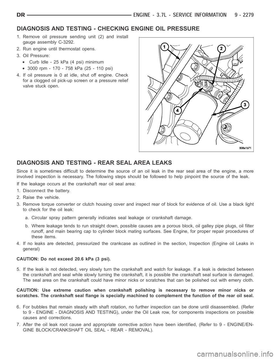
1. Remove oil pressure sending unit (2) and install
gauge assembly C-3292.
2. Run engine until thermostat opens.
3. Oil Pressure:
Curb Idle - 25 kPa (4 psi) minimum
3000 rpm - 170 - 758 kPa (25 - 110 psi)
4. If oil pressure is 0 at idle, shut off engine. Check
for a clogged oil pick-up screen or a pressure relief
valve stuck open.
DIAGNOSIS AND TESTING - REAR SEAL AREA LEAKS
Since it is sometimes difficult to determine the source of an oil leak in therear seal area of the engine, a more
involved inspection is necessary. The following steps should be followedto help pinpoint the source of the leak.
If the leakage occurs at the crankshaft rear oil seal area:
1. Disconnect the battery.
2. Raise the vehicle.
3. Remove torque converter or clutch housing cover and inspect rear of block for evidence of oil. Use a black light
to check for the oil leak:
a. Circular spray pattern generally indicates seal leakage or crankshaftdamage.
b. Where leakage tends to run straight down, possible causes are a porous block, oil galley pipe plugs, oil filter
runoff, and main bearing cap to cylinder block mating surfaces. See Engine, for proper repair procedures of
these items.
4. If no leaks are detected, pressurized the crankcase as outlined in the section, Inspection (Engine oil Leaks in
general)
CAUTION: Do not exceed 20.6 kPa (3 psi).
5. If the leak is not detected, very slowly turn the crankshaft and watch forleakage. If a leak is detected between
the crankshaft and seal while slowly turning the crankshaft, it is possible the crankshaft seal surface is damaged.
The seal area on the crankshaft could have minor nicks or scratches that canbe polished out with emery cloth.
CAUTION: Use extreme caution when crankshaft polishing is necessary to remove minor nicks or
scratches. The crankshaft seal flange is specially machined to complement the function of the rear oil seal.
6. For bubbles that remain steady with shaft rotation, no further inspection can be done until disassembled. (Refer
to 9 - ENGINE - DIAGNOSIS AND TESTING), under the Oil Leak row, for components inspections on possible
causes and corrections.
7. After the oil leak root cause and appropriate corrective action have been identified, (Refer to 9 - ENGINE/EN-
GINE BLOCK/CRANKSHAFT OIL SEAL - REAR - REMOVAL).
Page 1597 of 5267
FILTER-ENGINE OIL
REMOVAL
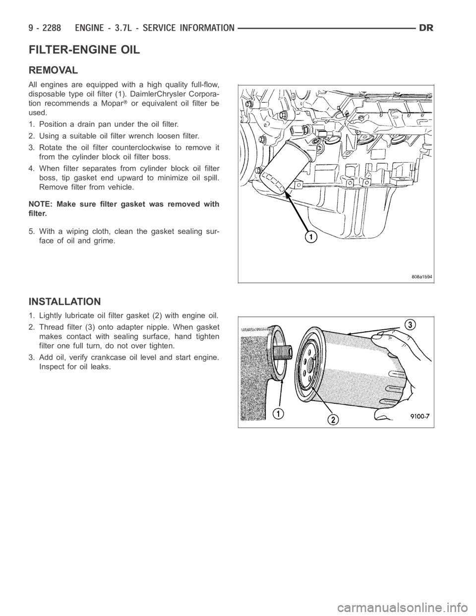
All engines are equipped with a high quality full-flow,
disposable type oil filter (1). DaimlerChrysler Corpora-
tion recommends a Mopar
or equivalent oil filter be
used.
1. Position a drain pan under the oil filter.
2. Using a suitable oil filter wrench loosen filter.
3. Rotate the oil filter counterclockwise to remove it
from the cylinder block oil filter boss.
4. When filter separates from cylinder block oil filter
boss, tip gasket end upward to minimize oil spill.
Remove filter from vehicle.
NOTE: Make sure filter gasket was removed with
filter.
5. With a wiping cloth, clean the gasket sealing sur-
face of oil and grime.
INSTALLATION
1. Lightly lubricate oil filter gasket (2) with engine oil.
2. Thread filter (3) onto adapter nipple. When gasket
makes contact with sealing surface, hand tighten
filter one full turn, do not over tighten.
3. Add oil, verify crankcase oil level and start engine.
Inspect for oil leaks.
Page 1606 of 5267
VALVE TIMING
DESCRIPTION
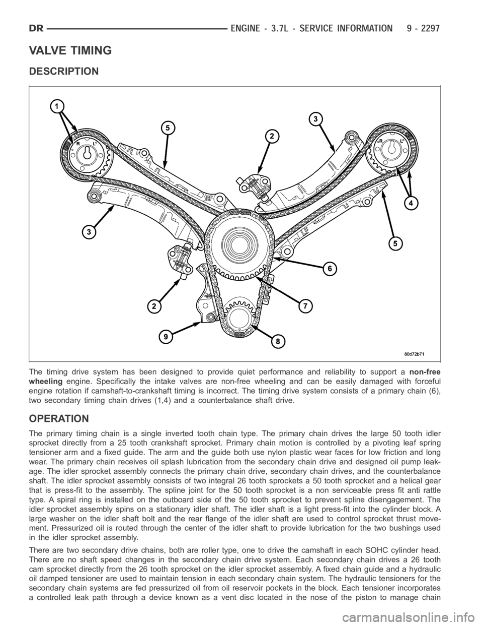
The timing drive system has been designed to provide quiet performance andreliability to support anon-free
wheelingengine. Specifically the intake valves are non-free wheeling and can be easily damaged with forceful
engine rotation if camshaft-to-crankshaft timing is incorrect. The timing drive system consists of a primary chain (6),
two secondary timing chain drives (1,4) and a counterbalance shaft drive.
OPERATION
The primary timing chain is a single inverted tooth chain type. The primarychaindrivesthelarge50toothidler
sprocket directly from a 25 tooth crankshaft sprocket. Primary chain motion is controlled by a pivoting leaf spring
tensioner arm and a fixed guide. The arm and the guide both use nylon plasticwear faces for low friction and long
wear. The primary chain receives oil splash lubrication from the secondary chain drive and designed oil pump leak-
age. The idler sprocket assembly connects the primary chain drive, secondary chain drives, and the counterbalance
shaft. The idler sprocket assembly consists of two integral 26 tooth sprockets a 50 tooth sprocket and a helical gear
that is press-fit to the assembly. Thespline joint for the 50 tooth sprocket is a non serviceable press fit anti rattle
type. A spiral ring is installed on the outboard side of the 50 tooth sprocket to prevent spline disengagement. The
idler sprocket assembly spins on a stationary idler shaft. The idler shaftis a light press-fit into the cylinder block. A
large washer on the idler shaft bolt and the rear flange of the idler shaft are used to control sprocket thrust move-
ment. Pressurized oil is routed through the center of the idler shaft to provide lubrication for the two bushings used
in the idler sprocket assembly.
There are two secondary drive chains, both are roller type, one to drive thecamshaft in each SOHC cylinder head.
There are no shaft speed changes in the secondary chain drive system. Each secondary chain drives a 26 tooth
cam sprocket directly from the 26 tooth sprocket on the idler sprocket assembly. A fixed chain guide and a hydraulic
oil damped tensioner are used to maintain tension in each secondary chain system. The hydraulic tensioners for the
secondary chain systems are fed pressurized oil from oil reservoir pockets in the block. Each tensioner incorporates
a controlled leak path through a device known as a vent disc located in the nose of the piston to manage chain
Page 1607 of 5267
loads. Each tensioner also has a mechanical ratchet system that limits chain slack if the tensioner piston bleeds
down after engine shut down. The tensioner arms and guides also utilize nylon wear faces for low friction and long
wear. The secondary timing chains receive lubrication from a small orifice in the tensioners. This orifice is protected
from clogging by a fine mesh screen which is located on the back of the hydraulic tensioners.
STANDARD PROCEDURE
MEASURING TIMING CHAIN WEAR
NOTE: This procedure must be performed with the
timing chain cover removed.
1. Remove the timing chain cover (Refer to 9 -
ENGINE/VALVE TIMING/TIMING BELT/CHAIN
AND SPROCKETS - REMOVAL).
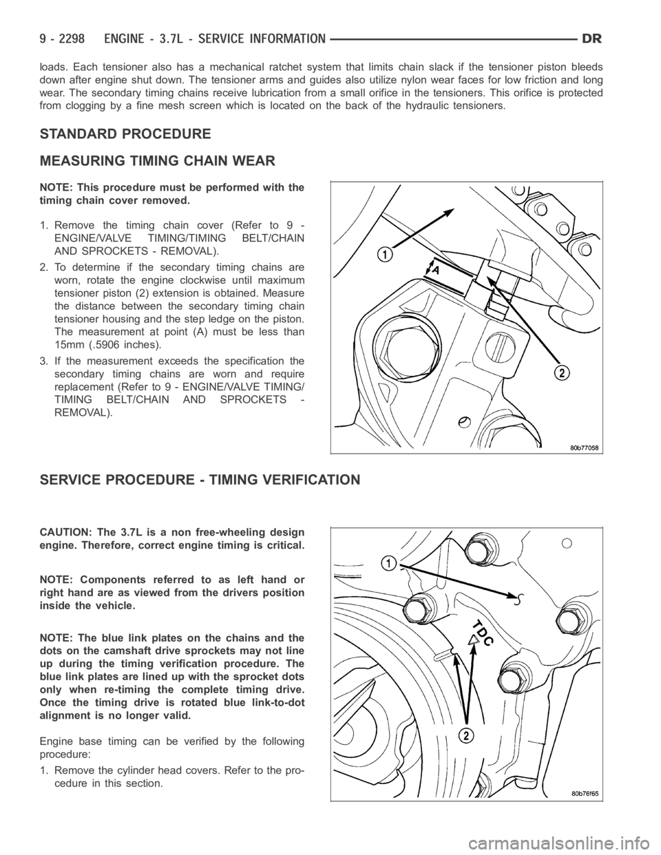
2. To determine if the secondary timing chains are
worn, rotate the engine clockwise until maximum
tensioner piston (2) extension is obtained. Measure
the distance between the secondary timing chain
tensioner housing and the step ledge on the piston.
The measurement at point (A) must be less than
15mm (.5906 inches).
3. If the measurement exceeds the specification the
secondary timing chains are worn and require
replacement (Refer to 9 - ENGINE/VALVE TIMING/
TIMING BELT/CHAIN AND SPROCKETS -
REMOVAL).
SERVICE PROCEDURE - TIMING VERIFICATION
CAUTION: The 3.7L is a non free-wheeling design
engine. Therefore, correct engine timing is critical.
NOTE:Componentsreferredtoaslefthandor
right hand are as viewed from the drivers position
inside the vehicle.
NOTE: The blue link plates on the chains and the
dots on the camshaft drive sprockets may not line
up during the timing verification procedure. The
blue link plates are lined up with the sprocket dots
only when re-timing the complete timing drive.
Once the timing drive is rotated blue link-to-dot
alignment is no longer valid.
Engine base timing can be verified by the following
procedure:
1. Remove the cylinder head covers. Refer to the pro-
cedure in this section.
Page 1608 of 5267
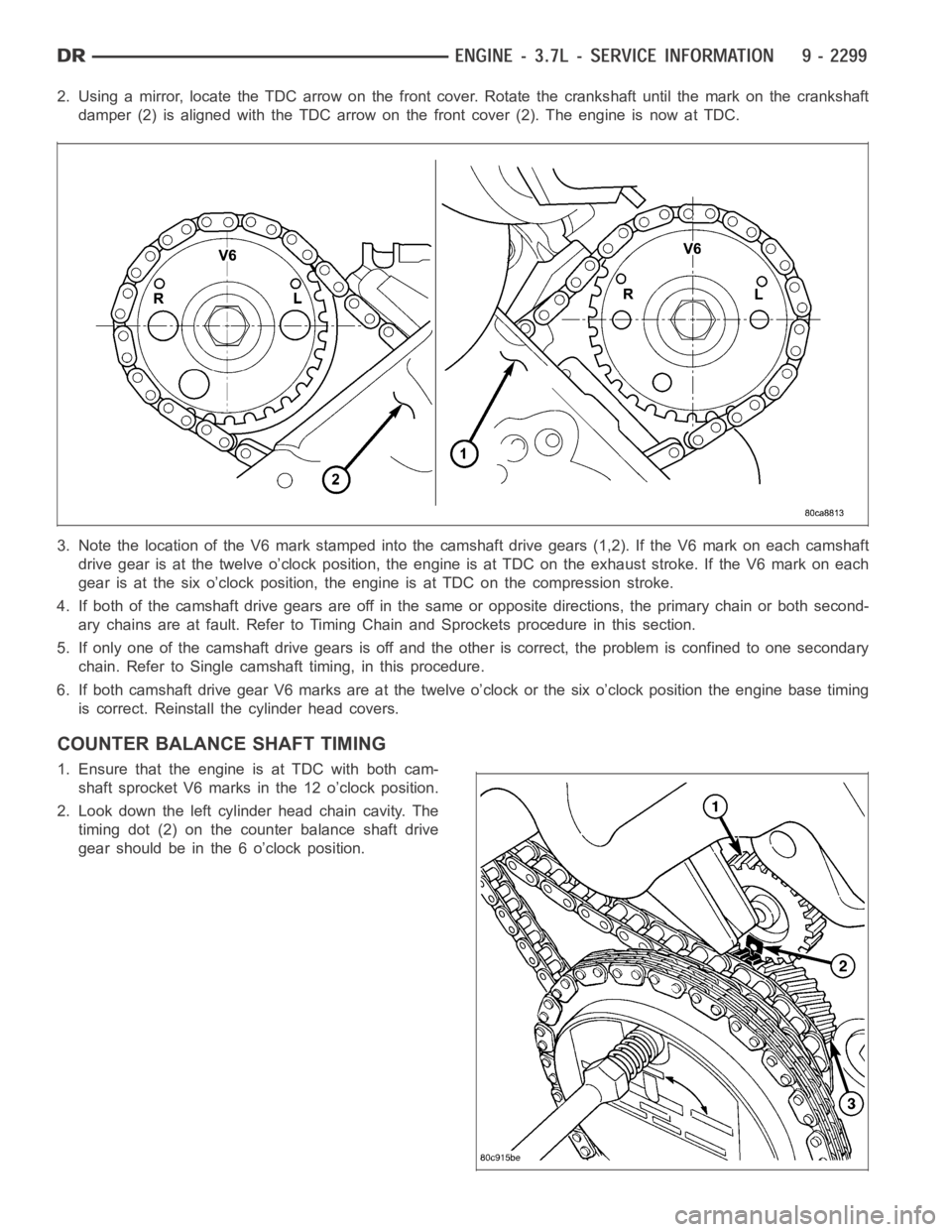
2. Using a mirror, locate the TDC arrow on the front cover. Rotate the crankshaft until the mark on the crankshaft
damper (2) is aligned with the TDC arrow on the front cover (2). The engine isnow at TDC.
3. Note the location of the V6 mark stamped into the camshaft drive gears (1,2). If the V6 mark on each camshaft
drive gear is at the twelve o’clock position, the engine is at TDC on the exhaust stroke. If the V6 mark on each
gear is at the six o’clock position, the engine is at TDC on the compression stroke.
4. If both of the camshaft drive gears are off in the same or opposite directions, the primary chain or both second-
ary chains are at fault. Refer to Timing Chain and Sprockets procedure in this section.
5. If only one of the camshaft drive gears is off and the other is correct, theproblem is confined to one secondary
chain. Refer to Single camshaft timing, in this procedure.
6. If both camshaft drive gear V6 marks are at the twelve o’clock or the six o’clock position the engine base timing
is correct. Reinstall the cylinder head covers.
COUNTER BALANCE SHAFT TIMING
1. Ensure that the engine is at TDC with both cam-
shaft sprocket V6 marks in the 12 o’clock position.
2. Look down the left cylinder head chain cavity. The
timing dot (2) on the counter balance shaft drive
gear should be in the 6 o’clock position.
Page 1614 of 5267
COVER-TIMING
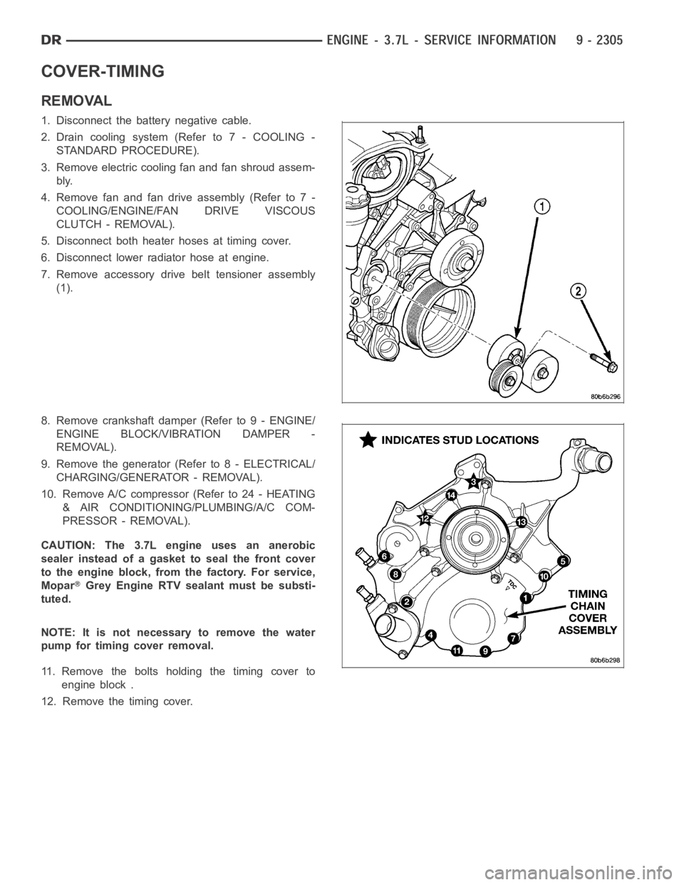
REMOVAL
1. Disconnect the battery negative cable.
2. Drain cooling system (Refer to 7 - COOLING -
STANDARD PROCEDURE).
3. Remove electric cooling fan and fan shroud assem-
bly.
4. Remove fan and fan drive assembly (Refer to 7 -
COOLING/ENGINE/FAN DRIVE VISCOUS
CLUTCH - REMOVAL).
5. Disconnect both heater hoses at timing cover.
6. Disconnect lower radiator hose at engine.
7. Remove accessory drive belt tensioner assembly
(1).
8. Remove crankshaft damper (Refer to 9 - ENGINE/
ENGINE BLOCK/VIBRATION DAMPER -
REMOVAL).
9. Remove the generator (Refer to 8 - ELECTRICAL/
CHARGING/GENERATOR - REMOVAL).
10. Remove A/C compressor (Refer to 24 - HEATING
& AIR CONDITIONING/PLUMBING/A/C COM-
PRESSOR - REMOVAL).
CAUTION: The 3.7L engine uses an anerobic
sealer instead of a gasket to seal the front cover
to the engine block, from the factory. For service,
Mopar
Grey Engine RTV sealant must be substi-
tuted.
NOTE: It is not necessary to remove the water
pump for timing cover removal.
11. Remove the bolts holding the timing cover to
engine block .
12. Remove the timing cover.
Page 1615 of 5267
INSTALLATION
CAUTION: Do not use oil based liquids to clean
timing cover or block surfaces. Use only rubbing
alcohol, along with plastic or wooden scrapers.
Use no wire brushes or abrasive wheels or metal
scrapers, or damage to surfaces could result.
1. Clean timing chain cover and block surface using
rubbing alcohol.
CAUTION: The 3.7L uses a special anerobic sealer
instead of a gasket to seal the timing cover to the
engine block, from the factory. For service repairs,
Mopar
Engine Grey RTV must be used as a sub-
stitute.
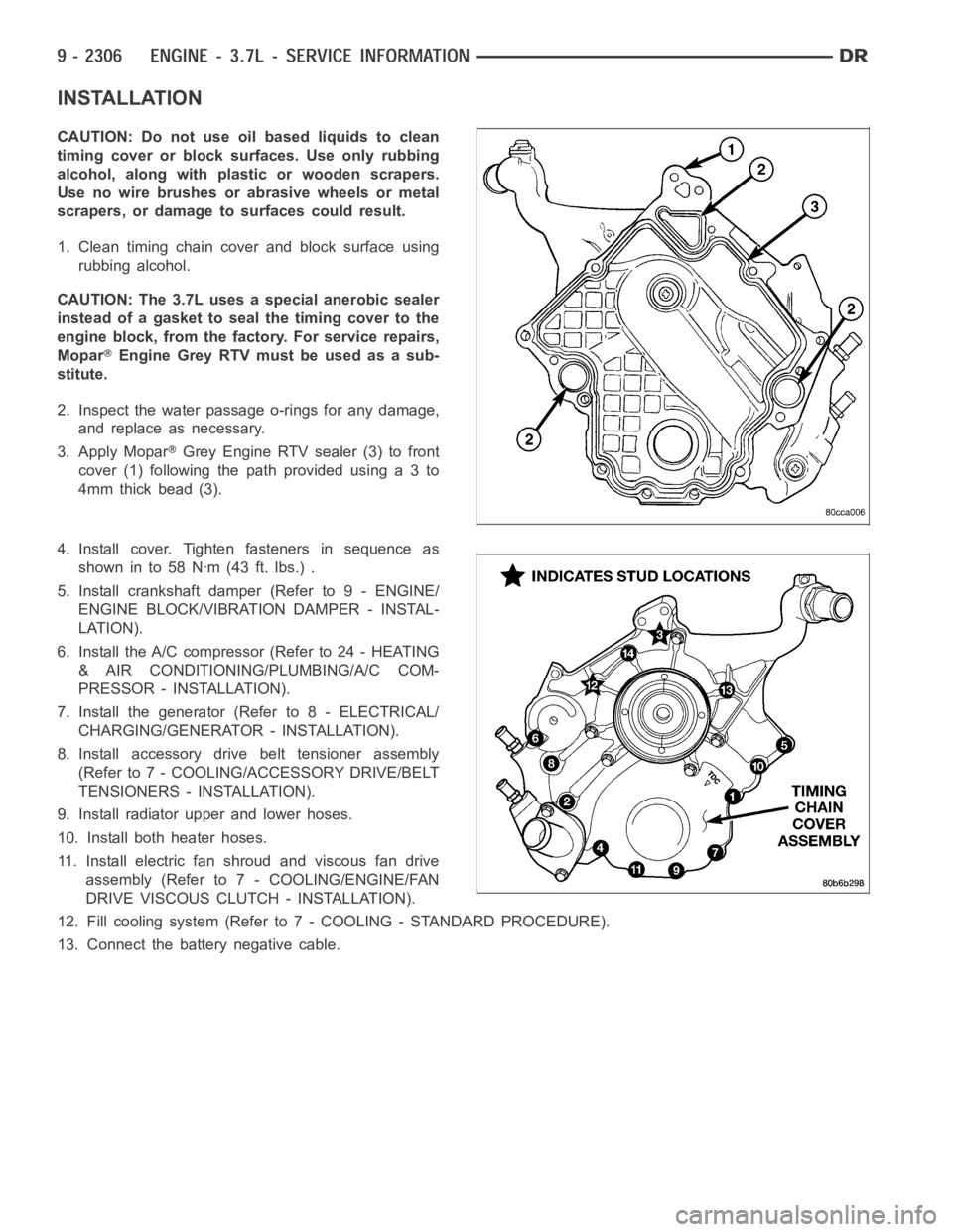
2. Inspect the water passage o-rings for any damage,
and replace as necessary.
3. Apply Mopar
Grey Engine RTV sealer (3) to front
cover(1)followingthepathprovidedusinga3to
4mm thick bead (3).
4. Install cover. Tighten fasteners in sequence as
showninto58Nꞏm(43ft.lbs.).
5. Install crankshaft damper (Refer to 9 - ENGINE/
ENGINE BLOCK/VIBRATION DAMPER - INSTAL-
LATION).
6. Install the A/C compressor (Refer to 24 - HEATING
& AIR CONDITIONING/PLUMBING/A/C COM-
PRESSOR - INSTALLATION).
7. Install the generator (Refer to 8 - ELECTRICAL/
CHARGING/GENERATOR - INSTALLATION).
8. Install accessory drive belt tensioner assembly
(Refer to 7 - COOLING/ACCESSORY DRIVE/BELT
TENSIONERS - INSTALLATION).
9. Install radiator upper and lower hoses.
10. Install both heater hoses.
11. Install electric fan shroud and viscous fan drive
assembly (Refer to 7 - COOLING/ENGINE/FAN
DRIVE VISCOUS CLUTCH - INSTALLATION).
12. Fill cooling system (Refer to 7 - COOLING - STANDARD PROCEDURE).
13. Connect the battery negative cable.
Page 1616 of 5267
CHAIN AND SPROCKETS-TIMING
REMOVAL
1. Disconnect negative cable from battery.
2. Drain cooling system (Refer to 7 - COOLING -
STANDARD PROCEDURE).
3. Remove right and left cylinder head covers (Refer
to 9 - ENGINE/CYLINDER HEAD/CYLINDER
HEAD COVER(S) - REMOVAL).
4. Remove radiator fan shroud (Refer to 7 - COOL-
ING/ENGINE/RADIATOR FAN - REMOVAL).
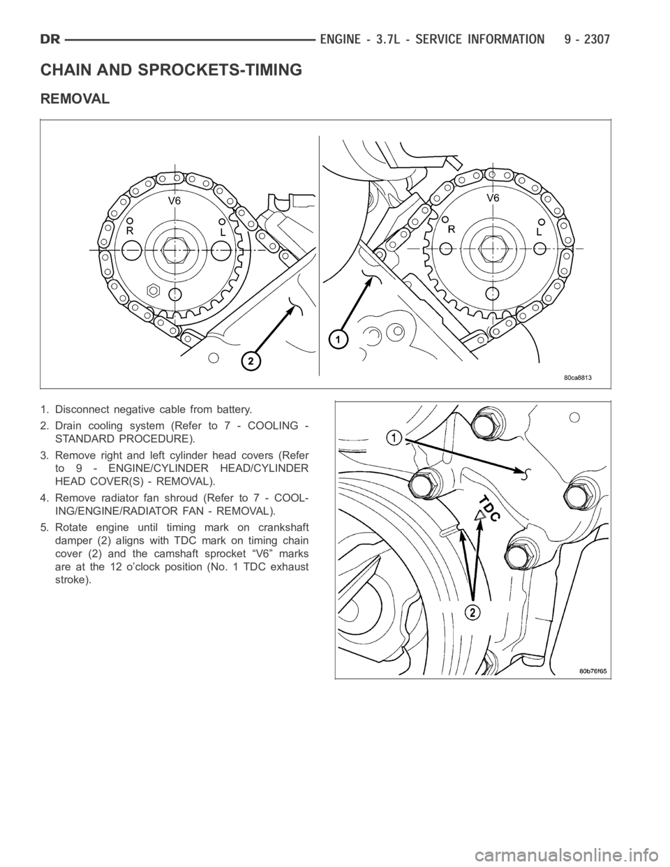
5. Rotate engine until timing mark on crankshaft
damper (2) aligns with TDC mark on timing chain
cover (2) and the camshaft sprocket “V6” marks
are at the 12 o’clock position (No. 1 TDC exhaust
stroke).