Page 2625 of 5267
3. Install sixth gear (1) on mainshaft (2).
4. Install sixth gear clutch body (1) on sixth gear (2).
5. Install sixth gear friction ring (1) on clutch body (2).
Page 2628 of 5267
11. Install fifth gear synchronizer clutch body (1) on
5-6 synchronizer hub (2).
COUNTERSHAFT
1. Install countershaft center support bearing (1) on
countershaft (2).
Page 2654 of 5267
47. Install input shaft seal in front housing with
Installer 9620 (1) and Tube C-3717 (2).
48. Install clutch bearing release support (1) and
tighten bolts (2) to 10 Nꞏm (88 in. lbs.).
49. Install Wrench 9586 (1) on input shaft (2).
Page 2656 of 5267
INSTALLATION
1. Clean transmission front housing mounting surface.
2. Apply light coat of Mopar high temperature bearing
grease or equivalent to contact surfaces of follow-
ing components:
release fork (1) ball stud (2)
release bearing slide surface (3)
input shaft splines (4)
release bearing bore (5)
propeller shaft slip yoke.
3. Support and secure transmission to jack.
4. Raise and align transmission input shaft with clutch
disc, then slide transmission into place.
5. Verify front housing is fully seated. Install transmis-
sion bolts without washers (1) and tighten bolts into
the engine to 41 Nꞏm (30 ft. lbs.). Tighten the bolts
with washers (2) into the transmission to 68 Nꞏm
(50 ft. lbs.).
6. Install rear crossmember (1) and tighten nuts to
102 Nꞏm (75 ft. lbs.).
7. Install transmission rear mount (2) bolts and tighten
to 68 Nꞏm (50 ft. lbs.).
Page 2664 of 5267

MANUAL TRANSMISSION-T56 - SERVICE INFORMATION
DIAGNOSIS AND TESTING
MANUAL TRANSMISSION - T56
LOW LUBRICANT LEVEL
A low transmission lubricant level is generally the result of a leak, inadequate lubricant fill or incorrect lubricant level
check.
Rear transmission leakswill be from the oil seals or component mating surfaces.
Front transmission leakswill be from the front bearing retainer or retainer seal. Lubricant may dripfromtheclutch
housing after extended operation. If leak is severe, it may contaminate the clutch disc.
Lubricant level checkcan only be made when the vehicle is level and allowing the lubricant to settle for a minute
before checking. This will ensure an accurate check and avoid an underfillor overfill condition.
HARD SHIFTING
Hard shifting is usually caused by low lubricant level, improper or contaminated lubricants. This will cause noise,
excessive wear, internal bind, and hard shifting. Substantial lubricantleaks can result in gear, shift rail, synchro, and
bearing damage. The first indications of component damage is usually hardshifting and noise.
Shift component damage, clutch adjustment, worn pressure plate or disc are also causes of increased shift effort. If
clutch problem is advanced, gear clash during shifts can result. Worn or damaged synchro rings can cause gear
clash when shifting into any forward gear. In some new or rebuilt transmissions, new synchro rings may tend to stick
slightly causing hard or noisy shifts. In most cases, this condition will decline as the rings wear-in.
TRANSMISSION NOISE
Most manual transmissions make some noise during normal operation. Rotating gears generate a mild whine that is
audible, but generally only at extreme speeds.
Severe, highly audible transmission noise is generally the initial indicator of a lubricant problem. Insufficient,
improper or contaminated lubricant will promote rapid wear of gears, synchros, shift rails, forks and bearings. The
overheating caused by a lubricant problem, can also lead to gear and bearing damage.
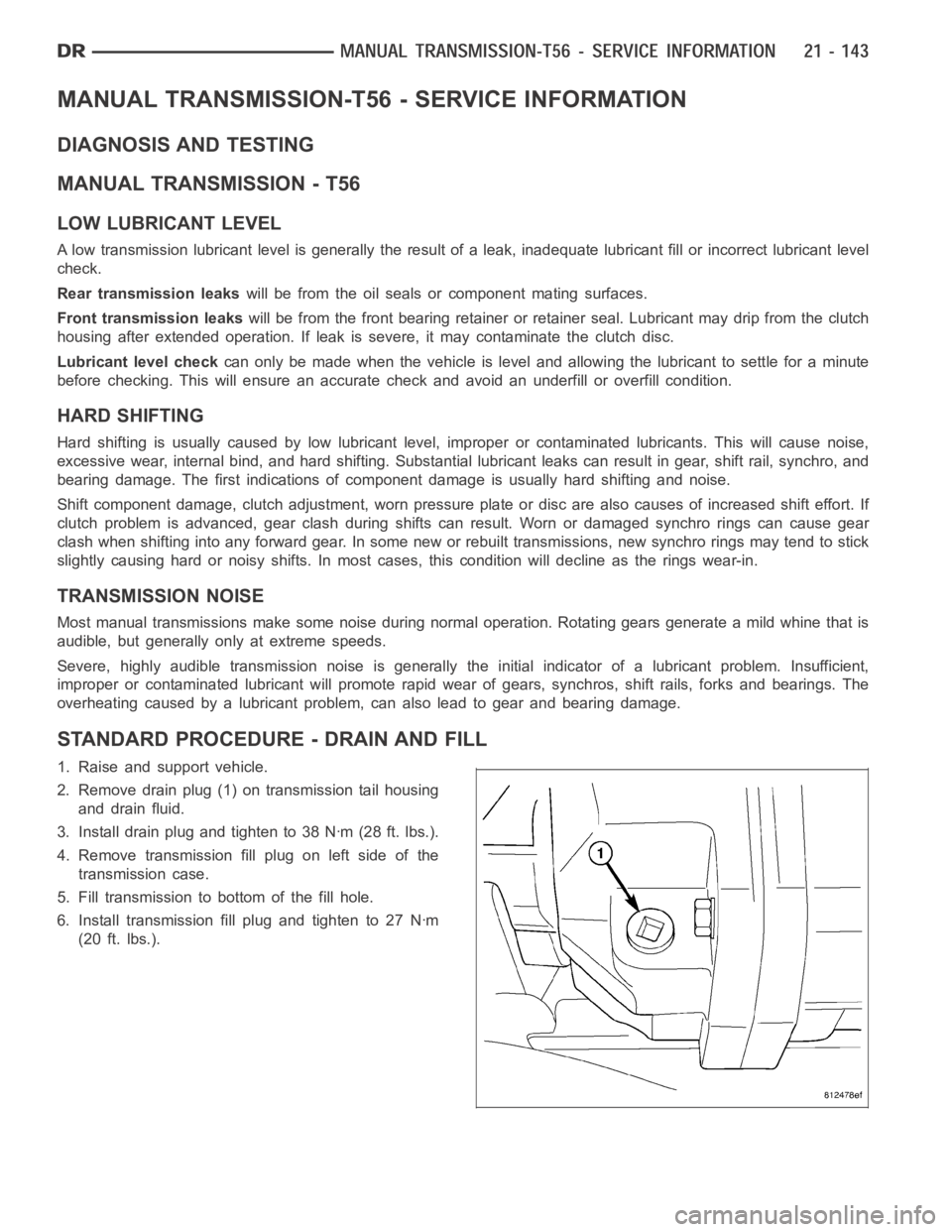
STANDARD PROCEDURE - DRAIN AND FILL
1. Raise and support vehicle.
2. Remove drain plug (1) on transmission tail housing
and drain fluid.
3. Install drain plug and tighten to 38 Nꞏm (28 ft. lbs.).
4. Remove transmission fill plug on left side of the
transmission case.
5. Fill transmission to bottom of the fill hole.
6. Install transmission fill plug and tighten to 27 Nꞏm
(20 ft. lbs.).
Page 2665 of 5267
REMOVAL
1. With vehicle in neutral, position it on a hoist.
2. Mark installation reference marks on the propeller
shaft, pinion yoke and transmission output shaft.
3. Remove propeller shaft (4) clamp (3) bolts (1) and
remove shaft.
4. Remove shift cover bolts.
5. Remove hydraulic clutch line (2) quick connector
(1) at the transmission with Clutch Line Disconnect
Tool 6638 or 6638A to disconnect.
Page 2666 of 5267
6. Remove reverse lockout solenoid (1) connector (2).
7. Remove fuel line clipfrom top plate stud.
8. Remove back up lamp switch (2) connector (1).
9. Position transmission jack (2) and secure to trans-
mission (1).
10. Remove transmission to clutch housing bolts.
Page 2676 of 5267
29. Remove two torx screws (2) located on the top of
the transmission case (1).
30. Remove clutch slave cylinder from transmission.
31. Remove all front adapter plate (2) bolts (3) except
one to hold the front adapter in place.
32. Stand transmission on Fixture 9387 and bolt
adapter to fixture.
33. Install on bench Fixture 9385.